(1)
The ridge waveguides is the most commonly used structure in integrated optics, especially in semiconductor diode lasers.Demands for new applications such as high-speed data backplanes in integrated electronics, waveguide filters, optical multiplexers and optical switches are driving technology toward better materials and processing techniques for planar waveguide structures. This paper addresses mainly the application of modal method to analyze the 3-D ridge waveguide structure. We have analyzed the modal index of ridge waveguide using various numerical methods based on Beam propagation method. Scalar, semi-vector, and full-vector propagation analysis are done for different etched film thickness (d). The results calculated by the proposed scheme for dispersion characteristics of ridge waveguides show good agreement with previously published data based on other rigorous numerical methods.
The rapid developments in the fields such as fiber optics communication engineering and integrated optical electronics have expanded the interest and increased expectations about guided wave optics in which optical waveguides play a central role. Compared to rectangular waveguides, ridge waveguides[1][2]have the advantages of wide fundamental-mode operation bandwidth, low cutoff frequency, and low wave impedance. Fundamental mode operation bandwidth of five to one or more is easily obtainable with ridge waveguides. Lower cutoff frequency yields a small cross section, and hence a compact size of ridge waveguide components. Shen [3] proposed to investigate length reduction of evanescent-mode ridge waveguide bandpass filters, and it is found that the filter length can be reduced by enlarging the evanescent waveguide height. Burton et. al.[4]performed the comparative analysis of the method of lines for threedimensional curved dielectric waveguides. They investigated three waveguide geometries: a ridge waveguide, a buried waveguide, and an interdiffused waveguide and compared the effective index method with both semi- and full-vectorial method of lines analyzing for these waveguide geometries. This comparison shows that the effective index method is accurate for curved waveguides except where the outer confinement region is in cutoff or, in the case of TM-polarization, for the ridge waveguide. In order to develop new optical communication systems or optical devices, we need to fully understand the principles of optical guiding, while obtaining accurate quantitative propagation characteristics of waveguides and utilizing them effectively in actual design. Three-dimensional analysis is necessary to investigate the transmission characteristics of ridge waveguides[5][15].
However, the rigorous three-dimensional analysis usually requires numerical calculations and does not always give a clear insight into the problem. Therefore, this paper describes two-dimensional slab waveguides to acquire a fundamental understanding of optical waveguides. Optical waveguides, which trap light locally and guide it in a specific direction, can be roughly classified into optical waveguides for optical integrated circuits and optical fibers. In this paper, the authors explained about the modal analysis of optical waveguides. The results are obtained from the OptiMode Solver. Then, they have shown the effect on the modal - index due to an etched film thickness for various propagations as scalar, semi-vector, and fullvector.
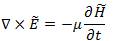
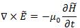
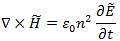
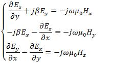
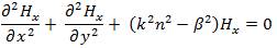
From the Maxwell's equations, one can directly derive the Holmholtz equations for a straight waveguide in the cartesian coordinate system [16].
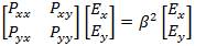
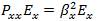
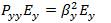
The solutions, that is, the eigenvalue and eigenvector of the above eigen-equation is called modes. In general, the mode of a general waveguide is both polarization dependent (Pxx ≠ Pyy ) and polarization coupled (Pxy ≠ 0, Pyx ≠ 0). Both are the result of dielectric discontinuties. The above equations are derived directly from Maxwell's equation without making any approximation. Hence, the solution is called full-vectorial mode. As evident from the formulation, a full-vectorial mode has two components. Note that one component is dominant and another component is small. Due to the singularity at the corners[17], the sharp peak of the minor component will further increase if smaller meshes are used. When the minor component is small, it can be ignored by letting P = P = 0. Then, the full-vectorial xy yx equation can be broken down into two decoupled “semi-vectorial” equations.
Solutions to the semi-vectorial equations are called semi-vectorial modes, which have only one component. In addition to the difference in modal profiles, the difference in effective indices between semi-vectorial and full-vectorial modes is also important
Taking into account the fact we treat dielectric optical 2 waveguides, we set permittivity and permeability as e = en0 and m = min Maxwell's eqs.(4)&(5)

as a result of
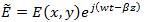
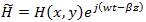
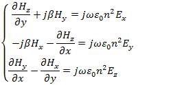
Where n is the refractive index.We are interested in planar-wave propagation in the form of
Substituting eqs (8)&(9)into eqs. (6)&(7), we obtain the following set of equations for the electromagnetic field components
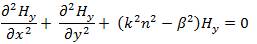
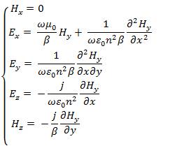
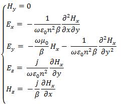
In this section the analytical method, which was proposed by Marcatili, to deal with the three dimensional optical waveguide, as shown in Figure 1, is described[5][6].There are nine distinct dielectric regions in this structure. The core (n ) is surrounded on every side by a lower index material. 1 The index in the shaded regions is neglected in the first order approximation to solutions to the waveguides. The regions are numbered for identification only, there is no implicit relationship between the various indices, except that n is larger than others. Analysis is difficult because it is 1 impossible to simultaneously satisfy all the boundary conditions in this structure. The difficulty in analyzing this structure originates in the four shaded regions. These regions act as the coupling zones for the x and y-solutions in the field. Well above cut-off, the electromagnetic mode is tightly confined within the core and the amount of energy in the corner region is negligible, so the wave equation can be solved using standard separation of variables. Near cutoff, however, the mode will have a significant amount of power in the corner regions. Therefore, neglecting the field in the corner regions will be the substance of our approximation [18][21]The important assumption of this method is that the electromagnetic field in the shaded area in Figure 2 can be neglected, since the electromagnetic field of the well guided mode decays quite in the cladding region. Then we do not impose the boundary condition for the electromagnetic field in the shaded area. We first consider the electromagnetic mode in which E and H are predominant.According to x y Marcatili's treatment, we set H = 0 in eqs(10)&(11). Then x the wave equation and electromagnetic field representation are obtained as,
Where,
On the other hand, we set H = 0 in eqs.(10)&(11)to y consider the electromagnetic field in which E and H are y x predominant. The wave equation and electromagnetic fields representation are given by
Where,
The modes in eqs. (12)& (13) are described as E x ( p and q pq are integers), since E and H are the dominant x y electromagnetic fields. On the other hand, the modes in eqs.(14)&(15) are called E x , since E and H are the pq y x dominant electromagnetic fields. The fields in various regions are summarized in [1].
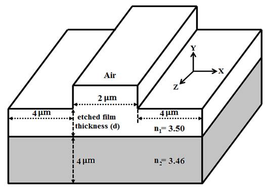
Figure 1. Front View of 3-D Ridge Waveguide
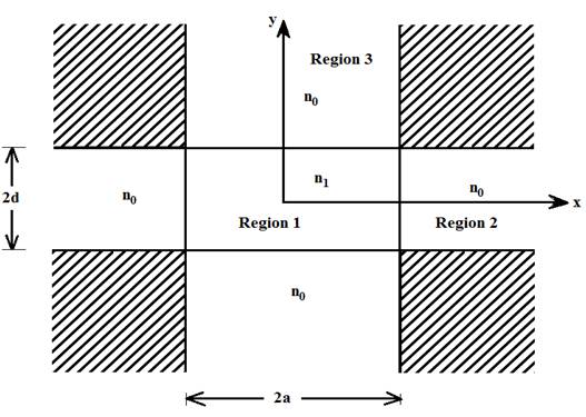
Figure 2. Three Dimensional Rectangular Waveguide
Now consider the Ridge waveguide to be analyzed, as shown in Figure 1. We have chosen below such the ridge waveguide design parameters so that it can support only for fundamental mode. Opti Mode is a suite of applications dedicated to mode solving. OptiMode has a Designer, Simulator, and Analyzer application for each of the three stages of the simulation. Simulations in OptiMode can be parameterized and executed in the script in the same manner as OptiBPM. We describe how to use the 3-D mode solvers of OptiMode. A typical ridge waveguide structure depicted in Figure 1, has etched film thickness (d). The refractive index of film (n = 3.50), substrate (n = 3.46), the 1 2 cover layers (n = 1.0) are considered in normal case. The air wavelength of propagation for various cases is considered to be l = 1.55mm. We also calculated the modal index (for fundamental mode) for different etched film thickness (d) and the results are shown in Table 1 & 2. It is apparent from Table 1 and Table 2 that, the difference between the semiand the full-vectorial propagation BPMs is small. Figure 3 shows the plot of modal index versus etched film thickness. It is apparent from Figure 3 that, normally modal index increases with the etched film thickness. For better field confinements, modal index should be high.
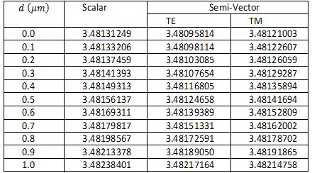
Table 1: The modal index for scalar and semi-vector polarization (for fundamental mode) of the ridge waveguide as the function of d.
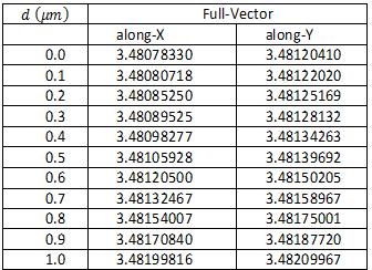
Table 2: The modal index for full-vector polarization (for fundamental mode) of the ridge waveguide as the function of d.
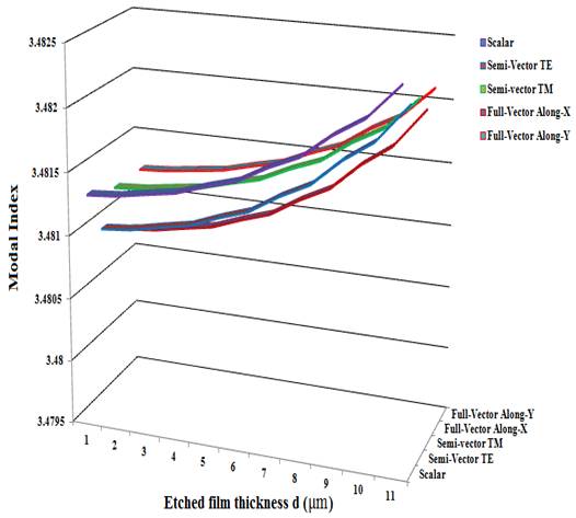
Figure 3: Plot of modal index versus Etched Film Thickness.
Figure 4 shows the 2-D Plot of optical field propagation, output field profile at fix x = 0 mm, output field profile at fix y = 0 mm and 3-D plot of optical field propagation respectively. It is apparent from Figure 4 that, pulse propagation in ridge waveguide is Gaussian. Figure 5 shows the 3D-plot of optical field propagation of ridge waveguide structure and Figure 6 shows the 3D-plot of refractive index profile of the ridge waveguide structure.
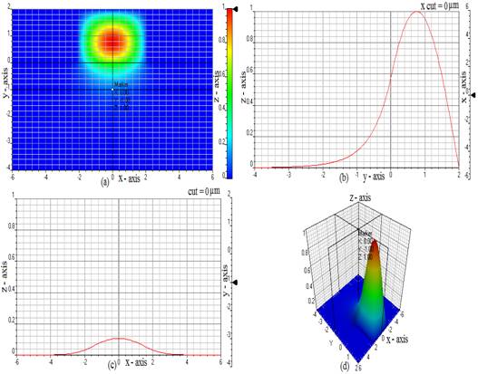
Figure 4: 2-D Plot of optical field propagation, output field profile at fixing x=0 μm, output field profile at fixing y=0 μm and 3-D plot of optical field propagation for the case of (a)-(d) Scalar mode propagation respectively.
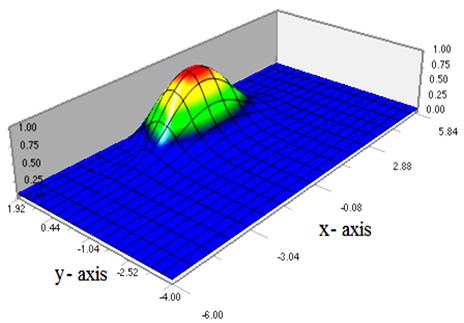
Figure 5: 3D-plot of optical field propagation of ridge waveguide structure.
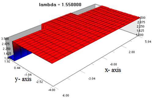
Figure 6: 3D-plot of refractive index profile of ridge waveguide structure.
We address mainly the application of modal method to analyze the 3-D ridge waveguide structure. In this paper, we have compared the modal index for the different case of propagation as scalar, semi-vectorial, and full-vectorial. Our study shows that modal index increases with the etched film thickness. Optical field propagation has been predicted. The mode field profile of the ridge section has been too studied with respect to etched film thickness. As the modal index increases due to an etched film thickness, better field confinements are possible. The ridge waveguide structure is widely used for active source like semiconductor lasers, modulators, switches, and semiconductor optical amplifiers, as well as passive device like coupler, combiner, mode converter etc. It is well known to combine the advantages of lower cutoff frequency of the dominant mode, wider bandwidth free from higher modes and low characteristic impedance. Our computational results have been exactly matched with existing results found in the literatures[11][15].