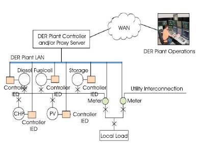
Figure 1. Conceptual Organization of DER System
Substation Automation Networks are increasingly deployed with devices adhering to IEC 61850 communication standards. Substation equipment can be categorized as critical infrastructure and hence the expectation on the availability and reliability is high. The high levels of availability in substations are required for the electronic devices and communication devices as well. Due to the nature of the application, the communication latency of the substation events shall be very high due to the criticality of the information carried in the network. One of the methods to improve the availability of the communication system is to provide redundancy. The IEC 61850 communication is based on the Ethernet and hence carries some disadvantages like very fast switch over and recovery in the event of link or switch failures. The paper aims at study of the redundant communication paths, recovery scenarios, tolerance levels, fault detection and associated impact on the communications. The above study is performed in the context of an automation system for integrating the Distributed Energy Sources to the Electrical Power System.
The substation automation networks meant for communication of intelligent electronic devices, HMI, engineering tools and other applications has moved fromproprietary to an open, standards based architecture. The IEC 61850 is a major mile stone in the electrical automation systems journey towards maturity [26], [31], [32]. The IEC 61850 standards were developed with the customization for the substation automation on the existing, commercially available communication standards like IEEE 802.3, IEEE 802.2 and ISO/OSI layers. The standard provides the ability of interoperability of the IEDs in the substation automation system. The IEC 61850 based substation automation system provides an easy way to integrate the various systems that provide an ability for substation monitoring, local and remote control, protection, equipment health monitoring and asset management. Among all the standards for DER systems, for substation automation IEC 61850 is flexible, future proofing, open standard, communication between devices in transmission and distribution [1].
IEC 61850-5 provided the message transmission times for the SAS and mandates specific latency needs to be achieved in all operating conditions [28]. Since critical automation systems are connected in the form of a network, any failure of the network can potentially make the system partially functional. Sometimes the partial functionality of SAS can make the substation vulnerable to failure of equipment or safety of the personal if the failure is related to the protection functions. The method to avoid such problems is to design a system for high availability. One of the well known methods to improve the availability is redundancy. The redundancy can be designed at an IED level (device level) and network level (link level). The current paper aims to study the link level redundancy for an IEC 61850. The device level redundancy is not in the scope ofthe paper.
Redundancy in network (link level) can be achieved either by having redundant ports or redundant media. The redundant port type consists of an IED with redundant network interfaces with redundant MAC and IP. Redundant media type is a network interface with single MAC and IP, but two media connections. The current paper evaluates the per formance of a redundant port type communications systems based on IEC 61850 and the performance impact of such a system [5]. This Ethernet based communication brings many advantages and some disadvantages [10]. One of the major problems of using Ethernet as a real time information and control network is its inability to provide a proper redundancy at link and physical network level [2], [4]. The parameters related to the time are very critical in substation automation systems [29]. The expectations are to have an ability to provide a system that can deliver a packet within 4ms reliability and repeatedly is one of the major requirement from a substation point of view
The case of redundant communication is more prominent, in an IEC 61850 scenario, if the protection equipment needs to communicate with other protection systems. The failure to communicate a command from one protectionsystem to another, leads to a catastrophic failure leading to burn of equipment and sometimes loss of life.
There are various papers available that made research on the communication network, End-To-End delays with various levels of bandwidth and physical media of IEC 61850 [19] [20] [21]. IEC 61850-7-420 Communication Networks and Systems for Power Utility Automation for Distributed Energy Resources (DER) provides a basis for information modeling, conceptual organization of DER logical devices and nodes. The DER controllers, protection systems will be tightly integrated with Electrical Connection Point (ECP) on the utility circuit breakers, load circuit breakers. Refer the Figure1 for the conceptual organization of DER system.
Figure 1. Conceptual Organization of DER System
The specifications have identified the logical nodes and logical devices for the elements. The logical nodes specified in these specifications [22] are addition to the existing LNs specified in [25]. The LDs are part and/or associated with the LDs. The LDs communicate with theactual signals as per the specifications IEC 61850-7-2 [24]. The Figure1. represents the architecture of an electrical power system integrated with the DER's [6]. The system is designed with IED's participating in IEC 61850 based communications. The IED's constitute the logical devices and nodes that communicate over the network for the data exchange [33]. The IED Layers can be found in the Figure 2.
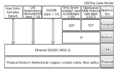
Figure 2. Layered Communication Model
IEC 61850 proposes OSI-7 layer based communication to provide flexibility in advancement of communication technology as shown in Figure 2. The seven types of messages are mapped into different communication stacks.
As shown in Figure 2, the raw data samples (type 4) and GOOSE (trip, block, interlock, etc.) messages (type1, 1A) are time critical messages and are, therefore, directly mapped to low–level Ethernet link layer [15], [18]. This gives the advantage of improved Performance for real time messages, by shortening the Ethernet frame (no upper layer protocol overhead) and reducing the processing time [14]. The medium speed message (type 2), the command message with access control (type 7), the low speed message (type 3) and the file transfer functions (type 5) are referred to as client-server communication and mapped to Manufacturing Message Specification (MMS) protocol suits, which have a Transmission Control Protocol/Internet Protocol (TCP/IP) stack above the Ethernet layer. Client-server communication includes information exchange like fault record, event record, measured value, etc. Moreover, it uses full Open Systems Interconnect (OSI) stack and hence it is more reliable data transfer. The time synchronization messages (type 6) are broadcasted to all IEDs in substation using User Datagram Protocol/Internet Protocol (UDP/IP).
The applications like GOOSE, Client Server MMS are service models at the applications layer. These are called ACSI (Abstract Communication Service) which defines common utility services for substation devices. The two groups of communication services are shown in Figure 3. One group uses a client server model with services like control or gets data values. A second group comprises a peer to peer model with GSE services (for time critical) such as protection IEDs. The data is meant for fast and reliable transmission of data between critical IEDs and also for the sampled value services for transmissions based on the periodic basis [7]. The clients and servers will be connected in various topologies, multiple physical media and can be at different geographic regions. The communication models will be transparent to the underlying methods, mechanisms and connections of the networks. The ACSI services are dominantly of type client server, GOOSE and SV.
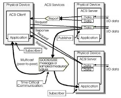
Figure 3. Communication Mechanisms Between Nodes
Client-Server: Client-server communication uses full seven layer stack with confirmed transmission layer. This is very reliable and relatively time consuming. Therefore, the client-server communication is not suited for time-critical data transmission but very well for the communication with an operator having a response time of the order of 1 s. The server is the source of all data for the client. The client asks the server for information and changes by parameter setting the behavior of the server issues commands via the server e.g. to switchgear configures at the server conditions which allow the server to send a report automatically to the client (report control block) The content of the report is defined by a data set. In contrast to master-slave multiple client-server links are possible [8].
Publish-Subscribe: The publish/subscribe model is needed for the information exchange service models such as GSE that require fast and reliable transmission of data to multiple receivers [3]. The GSE provides the mechanism of transferring event data over entire substation network. The event is received by multiple physical devices using multicase/ broad case services. The GSE model is further subdivided into GOOSE (Generic Object Oriented Substation Events) and GSSE (Generic Substation State Events).
Generic Object Oriented Substation Events (GOOSE) is a control model mechanism in which data (status, value) is grouped into a data set and transmitted within a time period of four milliseconds. The GOOSE transmission mechanism assures specified transmission speed and reliability. GOOSE data is directly encapsulated into Ethernet data packets and works on publisher-subscriber mechanism on multicast or broadcast MAC addresses. GOOSE uses VLAN and priority tagging as per IEEE 802.1Q to have separate virtual network within the same physical network and sets appropriate message priority level. GOOSE messages are retransmitted with varying and increasing re-transmission intervals. A new event occurring within any GOOSE dataset element will result in the existing GOOSE retransmission message being stopped. A state number within the GOOSE protocol identifies whether a GOOSE message is a new message or a retransmitted message. GOOSE messages are designed to be brand independent.
Generic Substation State Events (GSSE) is an extension of event transfer mechanism. Only Status data can be exchanged through GSSE and it uses a status list (string of bits) rather than a dataset as is used in GOOSE. GSSE messages are transmitted directly over IEC/ISO 8802-2 and 8802-3 using a similar mechanism to GOOSE messages (refer IEC 61850-7-1 Clause 12.2, IEC 61850-8-1 Clause 6.4). As the GSSE format is simpler than GOOSE it is handled faster in some devices [9].
As discussed in the earlier sections, the substation automation networks are expected to have high availability and one of the methods of improving the availability is through redundancy in the links. The concept of redundancy already exists in many automation networks. Redundancy of Ethernet based communication systems are defined and standardized in the Foundation Field bus networks for the industrial process automation systems [23]. The novelty here is to apply the same concepts with some customization to the IEC 61850 networks and measure the performance. The link redundancy provides alternate communication paths for the IEDs, networks can be designed such that no single communication path to/from the logical devices with in the sub network can cause overall loss of communications, and the status of the communication paths between IEDs is continuously monitored and assessed [17] [27]. Each IED participating in the network detects faults and takes the corrective actions based on the failures [13]. The failure detections and recovery actions are managed in a distributed manner by each and every participating IED rather than by some centralized methods. In this way, each IED is expected to publish the status of the links in a periodic basis to all the other participating IED's in the network. With this mechanism all the participating IEDs has a view or knowledge base of all the other IED's. This information will be used to identify the alternate path for all the communication link failures.
A link redundancy concept with the above characteristics built on Ethernet gives advantages of maximum use of the commercial off the shelf technologies and hardware, a transparent redundancy mechanism for the applications in substation automation and information technology as shown in Figure 4 [23]. With these advantages a special module called Link Redundancy Module (LRM) is developed. LRM is an entity in the application layer of the IED communication layer. LRM uses the TCP/IP or an optionally a direct MAC interface for sending the diagnostic packets and to receive the health of the links of the other participating IEDs. The LRM maintains a LSL as shown in Table 1 for the twelve IEDs. The key components of the LRM are given as follows.
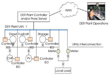
Figure 4. Modified Organization of Nodes with Redundancy
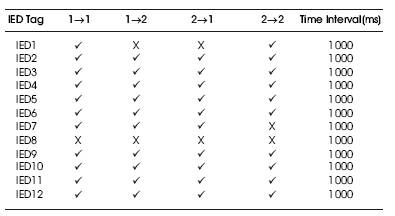
Table.1 Link Status List (LSL)
A diagnostic packet is a message which is summary information of the network and status as seen by the reporting IED. All the IED's participating in the redundancy will send diagnostic packets on each of the interface periodically. The receiving IED can recognize the absence of diagnostic packet from the other IED.
Each IED maintains a network status list that holds the IED view of the network. It is used by the IED to assist with selection of which interface or interfaces to use for transmission to a destination address and which interface or interfaces to use for reception of multicast transmissions. The Network Status List is constructed from received diagnostic packets described above.
Each uni-cast message (Client Server MMS protocol Suite based) sent by a link redundancy participating IED is sent from only one interface. Messages sent to multicast addresses (GOOSE, SV) may be sent from both interfaces, with the exceptions of link Redundancy Diagnostic packets. The IED evaluates its Network Status List and selects the interface or interfaces to use for each destination address. The interface(s) is (are) designated as the Transmission Interface(s) Used (TSU) for the specific destination address.
On some network topologies, a single operational multicast message can be received on each of a IED's interfaces. If a IED has two interfaces, the IED may be configured to use the Network Status List to select a reception interface for multicast operational messages, and so reduce its interrupt and message processing load. Note that the duplicates still need to be detected and discarded.
Each IED is configured using the IED configuration services as provided in the standard IEC 61850-7. The configuration determines the details of how each IED transmits diagnostic packet and how it uses the Network Status List to select transmission and reception interfaces. This information can be obtained from an IED by using the similar services. The IED's communicate in the system using client server mechanism or publish subscribe and report distribution mechanism as shown in Figure 3.
The behavior of the system for the client server communication using MMS suite during the link failure is on failure of network components, the client or the server (or both) may change its (their) selected transmission interface(s) to send subsequent messages. This has no impact on the client and server IP addresses being used; they do not change. No MMS Sessions are lost, though individual UDP messages may be lost (if UDP is being used).
Similarly for a publish subscribe, report distribution mechanism, Failures in the network may result in the Publisher/Report Source changing its Transmission Interface Used (TSU) or selecting both interfaces. Subscribers/Report Sinks take no action on network failures because they listen for messages on both interfaces.
LSL of an IED is shown in Table1. The LSL is maintained at each of the IED with the status of each link updated at a pre defined time interval. The time interval can be configurable based on the need of link failure detection times. As seen from IED1, if the 1->1 is not good, then the communication on the first link is failed. Similarly if 2->2 is not good, then the communication over the second interface is not good. If 1->2 or 2->1 is not good, then there is a problem in the cross communication.
The link failures can occur due to the failure of the multiple components in the communication subsystems. The figure above clearly depicts the failures from A to O, for such failure. The failure can occur in the network interface hardware in an IED (A), can occur in the port of the switch1(C), the physical cable failures (D) etc. The mechanism mentioned above detects the faults and recovers the same with the certain time. The key component for the detection of the failure is diagnostic packet. Each IED periodically sends a diagnostic packet on each of the interfaces to the other IED nodes. Each IED listens to the diagnostic packet from each of the peer IED. A packet missing from any interface indicates the potential network/link failure. In the case of the Figure 5, IED1 sends a diagnostic packet along the interfaces A and B. each packet will have a sequence number and IED 2 listens to these packets and will receive four packets on each of the IED. The IED will discard the duplicate packets generated by the switches based on the sequence number. IED 2 compares the each received packet's sequence number with previous sequence number. If the sequence number difference is more than certain configurable threshold, the IED declares the failure of the link. Each of the diagnostic packet will have a configurable parameter like ”pulse interval”, a time interval specifying how often a IED needs to send out a packet message on its interface, “MaxThreshold” a packet can be lost during transmission for various reasons. MaxThreshold (MT ) specifies the maximum number of the consecutive diagnostic packet lost on one interface that is tolerated by the failure detection scheme.
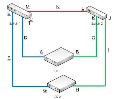
Figure 5. Link Redundancy of two IED's in a Network
Failure Detection Time is defined as the interval between the time a network failure occurred and the time the failure was detected and recovered. Given the two parameters like pulse interval (T ) and max threshold, failure detection pulse time by the IED is

Where Tprodelay and T p_Variation are configuration parameters specific to the type of the network topology and load.
Each IED maintains a view of the links in the form of LSL. The functionality of the LSL is provided in the sections above. In the current example assume if D and I are failed. Then the LSL appears as shown in Table 2. The actual values of the symbols/notations in a real time program depend on implementer's choice of programming.
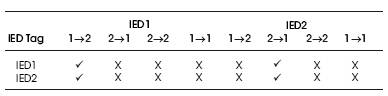
Table 2. Link Status List (LSL)
When IED 1 receives a diagnostic message from IED 2 via its interface 2(B), it sets “ok” in the IED1 entry of IED2 row and “1- >2” column of the LSL.
IED2 View is derived from the IED1 Views of the peer IED, which were received along with the diagnostic packets by the peer IEDs. For instance, since IED 2 tells IED 1 that it can receive the diagnostic packet from IED 1 via the 2->1 path, IED1's LSL sets “ok” in the entry of IED 2 row and “2->1” column of the LSL. Using the sequence numbers of received diagnostic packet, an IED declares network fault(s) if the following condition becomes true
Sequence # IED2 [G] - Sequence # IED2 [H] > (MTth + 1)
The detected fault(s) is reflected in the LSL as “X”or “0” as shown in Tables 1 & 2. Here there is no actual recovery process, but to transmit the packets in other interface.
OPNET is the discrete event simulator which is used extensively for research activities to study the performance and functionality of the network related studies [30]. The network model of the OPNET is shown in Figure.6. The simulation is considered with 12 IED's, each consisting of two interfaces and are connected to two different switches. The IED's in the network are considered as some meters, protection equipment and RTU's. The model of the system inside the IED's is considered similar for the simulation even though the LN's, LD's and other parameters may vary in actual systems. The opnet modeler has three levels of modules called as network model, node model and process model. For this case, the network model consists of two switches and twelve IEDs connected in redundant configuration. Figure 6 indicates the network model of the system in study. The nodes in the network are categorized as IEDs and PC based nodes like operations stations and engineering stations etc. The node models are developed with two variants meant for the embedded IED based and PC based nodes [11], [12], [16].
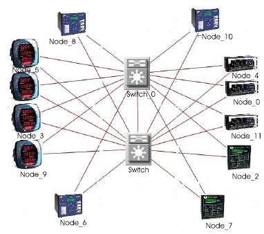
Figure 6. Network Model of DER System
The node model of an IED is developed with an application for providing the MMS services of the IED. The MMS services developed in the process data_srv in Figure 6 simulates the client server based communication. The profiles for the load and load characteristics were developed and provided to simulator at run time. The IED Node Model and PC Model both are provided with a process module with the name Link Redundancy Module (LRM). The node model of an IED is represented in Figure 7 and node model of a PC based IED node is represented in Figure 9. Both these models contain a module called LRM. The functionality of the LRM is to generate the GOOSE and SV packets and publish the same over the network. The LRM is also integrated with the Link Redundancy Logic as mentioned in the previous section. The process steps of the LSL process module gets initialized and register all the components. The diagnostic packets are generated and sent to all the nodes registered with the multicast address group. An LSL table gets initialized and starts publishing the packets. Each time interval, the process reads the packets diverted from the LRM for any multicast packets and updates the LSL based on the source MAC address of the packet. The LSL table gets updated by the process based on the sequence number with the threshold as explained in the earlier sections.
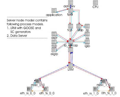
Figure 7. Node Model of an IED
A random link failure model is implemented as shown in Figure 8. The random link failure model fails the random selected links with used provided inputs like start time, stop time and repetition time. Even though OPNET provides an ability to fail the links and modules by user selection, study of the system performance at a user selected options is not considered correct. The failures in the real world can occur at any time and on any node. Hence random selection functions are utilized.
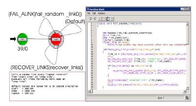
Figure 8. Random Link Failure Model
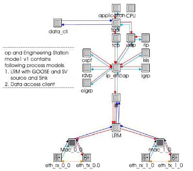
Figure 9. Node Model of an IED
The process model of the LRM is shown in Figure 10. The LRM is developed on the existing ARP model of the OPNET. The additional features and functionalities were added in the form of a C program. The LRM module is designed to have child process modules. The child process module is invoked at run time and meant for sending the diagnostic packets in the network and maintaining the Link Status List. The LRM diverts the packets on appropriate MAC/link based on the information available in the child process. The process model of the child process model is shown in Figure 11.
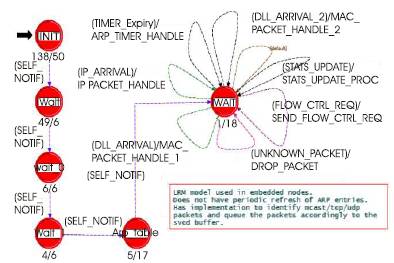
Figure 10. Process Model of LRM, GOOSE and SV
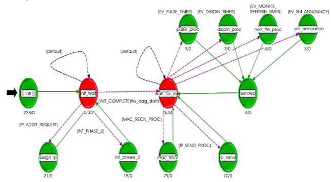
Figure 11. Process Model of List Status List
The system with the models provided in the above section is simulated. The random link failure model fails some of the links and the impact of these failures on the overall communication is studied.
Figure 12 indicates the results of a constant traffic sent from a IED and received by another IED. The failure of the link is represented in the diagram in second trend from top. The failure of the link immediately causes the IED to redirect the communication through the other switch and can see a sudden increase in the traffic from the second switch as shown in the third trend. The top trend in the figure below indicates that there is no loss of packets and packet/sec trend remains constant throughout the simulation time of 3600 seconds. The result indicates that the IED is able to switch the traffic between alternative path in the event of failure without loss of communication.
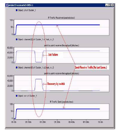
Figure 12. Link Fault Recovery
The random link failures are simulated and the results of the same are described in Figure13. Even though the random link failure module executes simultaneously with other models, for the purpose of illustration of the functionality, the results are shown separately. Figure13 has the trends of the communication between the links. The deep valleys in the figure indicate the link failures. The top trend indicates the failure of the link occurred in IED1 in port 1(A). The actual failure point can be understood by referring to Figure 5. The suffix A in the above failure condition is represented th pictorially in Figure 5. The first failure occurred at about 900 second and the duration was 300 seconds. The second th failure occurred at about 2000 second and duration was 600 seconds. The total duration of the simulation was 3600 seconds. A similar failure occurs across all the links at different times in the same simulation cycle.
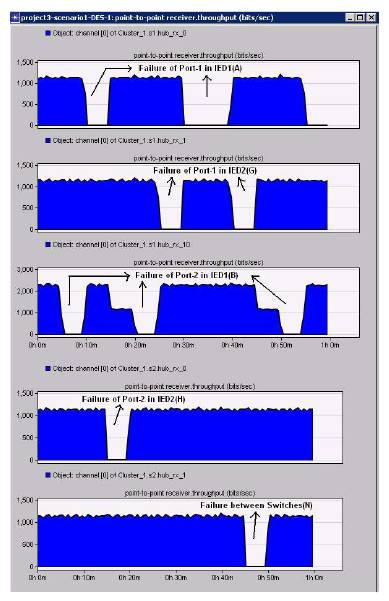
Figure 13. Random Link Failures Simulation
Figure 14 indicates the behavior during multiple link failures. The system was able to provide the alternate communication paths for some faults, but if the faults are more than or equal to 2, the failure is inevitable. The same is shown in Figure14. However, the system recovers immediately after the recovery of the link. The results indicate that there is no additional delay for the recovery of the communication immediately after the recovery of either link.
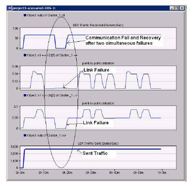
Figure14. Fault Recovery from Multiple Failures
The results represented in Figure 15 are similar to the results represented in Figure 14, with a difference to show the packet drops. The packet drops are measures across various failures in the links and found there is no packet drops during single failures. The packet drop is seen only in the case of both the link failures as shown.
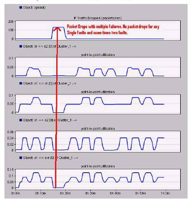
Figure15. Packet Drops due to Multiple Link Failures
The novelty of this paper is applying the same concept in an electrical utility automation. Based on the above simulation studies, the redundancy mechanisms are a need for the IEC 61850 and found suitable. The availability requirements for substation automation systems is also high and applying the redundancy concepts was found suitable and improves overall availability of the system while tolerating certain faults in the network without reducing or degrading the functional behavior of the IEDs.