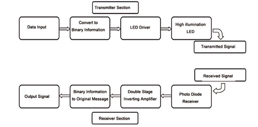
Figure 1. Block Diagram of Li-Fi Design (Lazar and Ravi, 2015)
Light Fidelity (Li-Fi) is a technology, which uses “illumination” method for transmitting data. The data is transmitted using Light Emitting Diodes (LED) and is received by photo sensor or detector. The objective is to transmit audio signal through Light Emitting Diodes and recover the data using Light Dependent Resistor (LDR). Li-Fi, an economical adaptation of Wireless Fidelity (Wi-Fi), provides high speed on the basis of visible light communication. Due to its better efficiency over radio based technology, it has become an idea of keen interest in the past few years. This technology not only increases speed of transmitting data but also increases the capacity, bandwidth, security, and reduces cost. This can be easily achieved by colour modulation or intensity modulation; thus it can be a good solution for all radio frequency issues.
Due to the increasing demand for wireless data communication, the available radio spectrum below 10 GHz (cm-wave communication) has become insufficient (Gawande et al., 2016). The wireless communication industry has responded to this challenge by considering the radio spectrum above 10 GHz (mm-wave communication). However, the higher frequencies, f, mean that the path loss, L, increases according to the Friis 2 free space equation (L α f ) (Haas et al., 2017). Light-Fidelity (Li-Fi) is a continuation of the trend to move to higher frequencies in the electromagnetic spectrum. Specifically, Li-Fi could be classified as nanometer wave communication. Li-Fi uses Light Emitting Diodes (LEDs) for high speed wireless communication. Visible Light Communication (VLC) uses LEDs to transmit data wirelessly by using intensity modulation (Haas et al., 2016). At the receiver side, the signal is detected by a LDR/photodiode by using the principle of direct detection. VLC has been conceived as a point-to-point data communication technique – essentially as a cable replacement. This has By led to early VLC standardisation activities as part of IEEE 802.15.7 (Institute of Electrical and Electronics Engineers) (Singh, 2015). This standard, however, is currently being revised to include Li-Fi. Li-Fi in contrast describes a complete wireless networking system. This includes bidirectional multiuser communication, i.e. point-tomultipoint and multipoint-to-point communication (Haas et al., 2016). As compared to general broadband connection, this technology provides higher data speed than 10 Mbps (Megabits per Second) which is much faster. Li-Fi is an Optical Wireless Communication (OWC) system, (Shrivas, 2015) which uses light from LED (light Emitting Diode), acts as a medium to deliver networked, mobile and high-speed communication similar to Wi-Fi. Both Wi-Fi and Li-Fi transmit data over the electromagnetic spectrum; only difference is that Wi-Fi utilizes radio waves whereas Li-Fi utilizes visible light. More specifically, in indoor communication where the demand of bandwidth is high and most mobile data traffic are required, light fidelity can be successfully used (Tsonev et al., 2014). Li-Fi related to Visible Light Communication (VLC) offers many key advantages, and effective solutions to the issues that have been posed in the last decade. Li-Fi has more advantages over Wi-Fi and limited disadvantages; also area of application of Li-Fi is wider than Wi-Fi.
The advantages of Li-Fi are as follows.
Li-Fi requires Line of Sight for efficient working, which is its only disadvantage.
The applications of Li-Fi are as follows
This paper is basicaly a design of audio transmission system for understanding the implementation of VLC with LED other than laser with Optical Fibre Coupling (OFC). The rest of the paper is structured as follows, In Section 1, a brief history of this technology is discussed. A general working of Li-Fi is explained in Section 2, followed by special function of this design. In the same section comparisons with existing technology and design are detailed. Finally, this lead to results in Section 3 and Conclusion part.
Professor Harald Haas, from The University of Edinburgh in UK, is widely recognised as the original founder of Li-Fi. He coined the term 'Li-Fi' and is Chair of Mobile Communications at The University of Edinburgh and cofounder of pure Li-Fi. Term Li-Fi is common after TED Conference Global talk (Technology, Entertainment, Design) where the idea of "Wireless data from every light" was introduced by him. The general term Visible Light Communication, includes any utilization of the visible light portion of the electromagnetic spectrum to transmit information and this light is to be called as D-Light, which can provide very high speed connection (Sharma and Sanganal, 2014).
This technology was a part of VLC which was introduced in 1880's, but this technique originally rose in 1990's in different countries like Germany, Korea, and Japan with the idea of retrofitting the LED's for transmitting data. Initially different forms of light are used such as infrared, ultraviolet and visible light. Researches had been conducted in early 2003 in different centres to show dual functionality of LED as a wireless transmitter, as well as with its main function spreading of light. This is cheaper, safe and fastest than other wireless devices like Wi-Fi, Bluetooth etc. Haas had a fully loaded lab of equipment with his famous table lamp. His assistant, Mostafa Afgani, used to show the transmission. Their centre work focussed on how to modulate these signals with the required information enclosed within visible light emitted from the LED's with ultra-high rate of 100 million cycles per second (100MHz). It is also more secure than other wireless networks as only photo receptors are used, which can receive data within transmitted cone of light signals. In October 2011, companies and industry groups formed the Li-Fi Consortium, to promote high-speed optical wireless systems and to overcome the limited amount of radio-based wireless spectrum available by exploiting a completely different part of the electromagnetic spectrum (Navyatha et al., 2013). A number of companies offer unidirectional VLC products which are not same as Li-Fi. VLC technology was exhibited in 2012 using Li-Fi. By August 2013, data rates of over 1.6 Gigabits/s were demonstrated over a single color LED. In September 2013, a press release said that Li-Fi or VLC systems in general, do not require line-of-sight conditions. In October 2013, it was reported that Chinese manufacturers were working on Li-Fi development kits (Li-Fi). Recently integrated Complementary Metal–OxideSemiconductor (CMOS) optical receivers for Li-Fi systems were implemented with Avalanche Photodiodes (APDs) which have low sensitivity. In July 2015, IEEE has operated the APD in Geiger-mode as a Single Photon Avalanche Diode (SPAD) to increase the efficiency of energy-usage and make the receiver more sensitive (Li-Fi, n.d.).
The general concept of transmitting data can be easily explained. If the LED is ON, the data is transmitted, (i.e.) a digital 1 is transmitted; and if the LED is OFF, a digital 0 or null is transmitted, or simply no data transfer happens (Panjwani and Abhinav, 2017). One can switch them on and off very quickly and transmit data easily, because the LED's intensity is modulated so rapidly that, human eye cannot notice. The output in the form of light appears constant, thus offering permanent connectivity. More sophistication in the transmission techniques can further increase the data rates through VLC. Figure 1 shows the block diagram of Li-Fi design (Lazar and Ravi, 2015). Figure 2 shows the block diagram of circuit for implementation of audio transmission via LED and reception via LDR.
Figure 1. Block Diagram of Li-Fi Design (Lazar and Ravi, 2015)
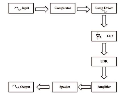
Figure 2. Block Diagram Implementation of Audio Transmission Via LED and Reception via LDR
Figure 3 shows the transmitter circuit for data transmission. In this circuit, op-amp 741 is used as a comparator for analog to digital conversion. A variable resistor is used as gain controller to control output volume of the op-amp. Q1 transistor is used for amplification and modulation. The transistor will act as lamp driver to drive the LED. LED emits light according to the pulse waveform and makes VLC alive. Since blinking of LED is controlled by the input signal, it will take place in nanoseconds (ns) and cannot be detected by Human eyes.
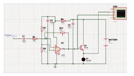
Figure 3. Li-Fi Audio Transmitter Circuit
Figure 4 shows the LDR receiver circuit for data transmission. In the receiver circuit, one end of the resistor is connected to high potential of variable DC power supply and another end is connected to LDR. Other end of LDR is grounded. Here, variable DC power supply is used for LDR, so that one can control the volume of audio in receiver circuit, unlike in photodiode/solar cell where this option is not available. The analog output of LDR is then amplified using BC 548. It also helps in removing any phase changes occuring in the transmitted signal. An amplified signal is fed to the speaker. The speaker converts the analog signal to the audible sound signal using the electromagnet present in the speaker.
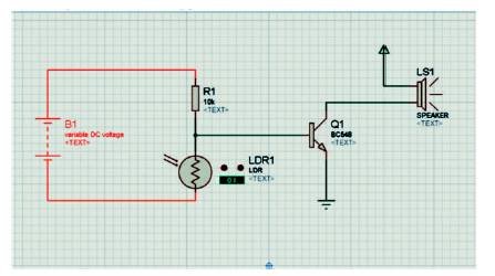
Figure 4. Li-Fi Audio Receiver Circuit
Figure 5 shows the transmitter circuit simulation. The first sine wave signal shown in Figure 5 is considered as audio analog input of frequency ranging from 20 Hz to 20 KHz. The second wave is a low power, low amplitude signal which is the output of operational amplifier. The third amplified output is obtained from BC548 transistor, which is fed to LED (transmitter).

Figure 5. Transmitter Circuit Simulation
Figure 6 shows transmitter and receiver circuits implanted on the same board. Both the circuits are separated in the same board. Left upper pin is the input for circuit whereas, lower pin is the output. Right pins are power supply for both transmitting and receiving circuits.
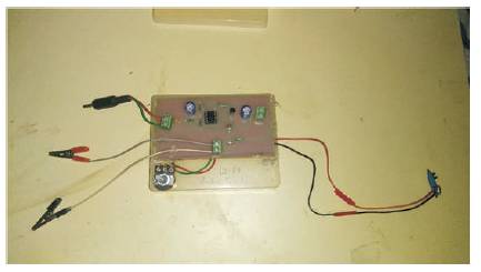
Figure 6. Transmitting and Receiving Circuit
As shown in Figure 7, data are inputted into the circuit and all the required connections are set and then the output data will be emitting from LED. In the same fashion, LDR which is just in front of LED receives the desired signal
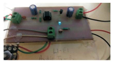
Figure 7. Audio Data Transmission through LED
Figure 8 shows all the required connections for working, which include power supplies, input signal (mobile), speaker for output and circuit. Tables 1 and 2 show the comparison between transmission technologies and, Wi-Fi and Li-Fi, respectively.
Figure 8. Whole Setup
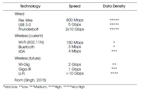
Table 1. Comparison between Transmission Technology
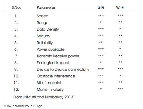
Table 2. Comparison between Wi-Fi and Li-Fi
Results shows that the desgined circuit for audio signal transmission using Li-Fi is working properly. Here, transmitter and receiver are on the same board for demonstration where LED acts like transmitter and LDR as receiver. Here amplifier and speaker are not separately used in the receiving section instead, speaker with in-built amplifier has been used. Li-Fi has a great potential in the field of wireless data transmission. The people who are accessing internet are continuously increasing at a very rapid rate, as a result internet with wifi has limitations and will be insufficient. Hence, Li-Fi proves to be a successful replacement of conventional wireless system, as it can easily provide high speed internet access.
Nowadays, it is possible to use LED Wi-Fi transmitter for data transmission. Each Li-Fi bulb has a potential to be used as Wi-Fi hotspot. It proves to be the most efficient upcoming technology as Li-Fi is leading us toward a greener and safer future. It also provides a three-fold security; practical, logical and on health basis. This technology can be used over those places where radio waves are restricted. The most attracting feature of Li-Fi is that it is free to use and there is no requirement of licence. Few challenges in Li-Fi are, external light sources such as sunlight, normal bulbs, and opaque materials which can interfere and provide less reliability. It works on Line of Sight (LoS) principle so if receiver is blocked due to any reason, signal will not be received.