Figure 1. Fine Grain Mode Prediction
This paper proposes a fine-grain-mode prediction for variable stage pipeline processor. Fine-grain controller adjusts the pipeline depth at every several tens of cycles and also predicts the suitable pipeline depth using a processor counter like as a cache hit counter or an each instruction counter. This method is used for variable stage pipeline (VSP) processor. A VSP processor varies in the pipeline depth dynamically according to workload. Based upon the workload the fine grain mode prediction unifies the pipeline stages. So, the power consumption reduces and increases its performance. A similar approach was proposed by Yao et al [3]. After 1 year the fine-grain control was proposed but their approach does not consider for the detailed mechanism to change pipeline depth with small penalty. To take advantage of fine-grain controlling of pipeline unification, it is essential to change pipeline depth without incurring a large penalty. This mode predictor is used for 7-stage pipeline processor. So that unification of the processor has been done and analyzing operation performed in the processor. This method is essential to change pipeline depth without incurring a large penalty.
For both high performance and low energy consumption we have considered the fine-grain controller. The reduction of power consumption is associated with the performance minimization, and the pipeline depth need to be adjusted to suitable depth according to the current workload and also program feature. Previous work does not have the hardware mode controller and do not assume to control pipeline depth and also doesn't predict the suitable pipeline. It is very difficult to go for sharp workload fluctuations [1], [2]. Energy consumption is decreased by Pipeline Stage Unification (PSU) method; also it changes the pipeline depth for the need of high performance [5]. This scheme uses the fine grain control method [3]. This method does not consider detailed mechanism. Therefore, the fine-grain controller is used to adjust the pipeline depth for every several ten of cycles [8]. The mode switching is possible to shift between one mode to other mode [4]. This fine grain mode prediction mechanism is applied to 7 stage pipeline processor so that, the processor unification (stage reduction) has been done and the operation is performed inside the processor.
This proposed mechanism overlaps the pipeline flushes so that it can hide the overhead. The power consumption increased and degradation of performance occurred in the case of changing the pipeline depth requiring pipeline flush that becomes large latency overhead. This fine grain mode prediction is applied to the pipeline processor, so that it can predict the suitable pipeline depth according to the workload. Also, unification of pipeline depth is done [10].
The fine grain mode predictor predicts the suitable pipeline depth [6-8] using the processor counter. The method is based on dynamic memory access analysing and it reduces energy consumption. This fine grain mode prediction is applied to the pipeline stage for unification. Here this mechanism is analyzed for 7 stage pipeline processor. Under high speed mode this instruction is lower than the threshold for unification; under low-energy mode the instruction is larger than the threshold for making deep pipeline [10].
An instruction pipeline is a technique which is used in the design of computers to increase their instruction throughput (the number of instructions that can be executed in a unit of time). The basic instruction cycle is broken up into series called a pipeline. Rather than processing each instruction sequentially (one at a time, finishing one instruction before starting the next), each instruction is split up into a sequence of steps so different steps can be executed concurrently (at the same time) and in parallel (by different circuitry).
Pipelining increases instruction throughput by performing multiple operations at the same time (concurrently), but does not reduce instruction latency (the time to complete a single instruction from start to finish) as it still must go through all steps. Indeed, it may increase latency due to additional overhead from breaking the computation into separate steps and worse, the pipeline may stall (or even need to be flushed), further increasing latency. Pipelining thus increases throughput at the cost of latency, and is frequently used in Central Processing Unit (CPU), but avoided in realtime systems, where latency is a hard constraint.
Each instruction is split into a sequence of dependent steps. The first step is always to fetch the instruction from memory; the final step is usually writing the results of the instruction to processor registers or to memory. Pipelining seeks to let the processor work on as many instructions as there are dependent steps, just as an assembly line builds many vehicles at once, rather than waiting until one vehicle has passed through the line before admitting the next one. Just as the goal of the assembly line is to keep each assembler productive at all times, pipelining seeks to keep every portion of the processor busy with some instruction. Pipelining lets the computer's cycle time be the time of the slowest step, and ideally lets one instruction complete in every cycle.
The fine grain mode predictor has different block each of which performs different function.
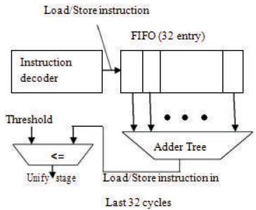
Figure 1 shows the block diagram of fine grain mode prediction used to predict the suitable pipeline depth and also adjust the pipeline depth. Very first block is First In First Out (FIFO) next one is adder tree and final block is comparator. Comparison has been done with the help of threshold and the output of adder tree.
Figure 1. Fine Grain Mode Prediction
In Figure 1 the very first block is FIFO. This block is used to receive the number of decoded load and store instruction, and holds them for 32 cycles. FIFO performs the load and store operations ie, read and write operation. Instruction is received by FIFO which will be write on to each cycle ie, up to 32 cycles [8-10]. During read operation, the instruction is read based upon the arrival of stored instruction ie, whatever stored first will be read first and follows on the same basis of stored instruction. Load is used to load a value from memory and copy the data from memory into a register. Store is used to store a value to memory and copy the data from register to memory.
The adder tree network computes the sum which is compared to a threshold. Figure 2 shows the adder tree, that counts the number of inputs that is provided in FIFO block. FIFO block performs the read and write operation based upon what the adder tree counts. During write operation the count will be increased and during read operation the count will be decreased. Adder tree sums up the number of decoded load/store instruction in the latest 32 cycles [8]. Load instruction is nothing but read instruction. Store instruction is write instruction. This read and write operation will be performed in FIFO. If the sum is larger than the fixed threshold, the workload may become low, therefore the unify stages signal is asserted to shift into the low-energy mode.
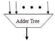
Figure 2. Adder Tree
Threshold value is based on the summing process. If the adder tree sum is larger than the fixed threshold, the workload may become low. Therefore the unify stages signal is asserted to shift into low-energy mode or otherwise it un-unifies the pipeline stage. It reduces the power consumption and increases the performance.
When workload is high then the processor shifts into highspeed mode by un-unifying pipeline stages. When the workload is low, then the processor shifts into low-energy mode by unifying pipeline stages [3-5]. Here we are going to show how the unification comes, and assigns the threshold based upon the cycle. Here considering pipeline as, 7 stage pipelines.
Figure 3 shows that, if adder tree count is larger than the threshold value, the pipeline stage will be reduced ie, pipeline stage unification. Pipeline unification is based on the workload that is instruction count in the output of adder tree. Adder tree adds the load and stores instruction that will be performed in FIFO. This reduction of pipeline stage causes reduced power consumption and increases the performance.
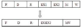
Figure 3. Pipeline Stage Unification
Here, we are considering the processor as 7-stageprocessor. Figure 4 shows that when the workload is high or high performance is required, the processor shifts into high-speed mode by un-unifying pipeline stages, and is driven at a high clock frequency. When the workload is low or high performance is not required, the processor shifts into a low-energy mode by unifying pipeline stages and is driven at a low clock frequency. The stages are indicated as F-fetching, D1-operand & operation decoding1, D2- operand & operation decoding2, E1&E2-exection1&2, MRE (Memory Write Enable), MR (Memory Write).
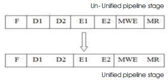
Figure 4. Pipeline Stage Unification
Figure 5 shows the fetching operation of the processor. Here, assuming 22-bit instruction, in this first 4-bit is considered as operand decoding1 another 4-bit is operand decoding2, next 6-bit is considered as operation decoding1 and 2. Last 8-bit is for memory access that is for storing final output.
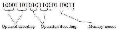
Figure 5. Fetching Operation
This 4-bit operand address stores the input values and 3- bit operation address stores the operation that should be assigned to input values. Based upon this operation, the execution process is done for the input values. So the operation is performed in execution 1 and 2. The final result is stored in memory address. If memory write enable is 1 then it reads the output in memory address. Pipeline depth value is nothing but it comes from output of fine grain mode mechanism. If unification is done then it gives '1010101' otherwise '1111111'. So, considering this as selection input and applying to processor, the pipeline unification is done in processor.
Here, between stages a special register is used called as LDS-cell (Latch D-flipflop Selector-cell).
To prevent glitch propagation, VSP technique introduces the latch D-FF selector-cell (LDS-cell) shown in Figure 6 as a pipeline register instead of the DFF+MUX.
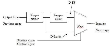
Figure 6. Special Register LDS-cell
This paper is implemented, because fine grain mode prediction is mainly used for unifying pipeline stages. This fine grain mode mechanism is implemented in 7-stage pipeline processor so that it unifies (reduction of pipeline stage) the pipeline processor stages and analyzes the process performed in 7-stage processor. In this fine grain mode prediction each block performs different function.
The complete process of fine grain mode prediction is nothing, but for example based upon the input. The count will be calculated as 16, that will be compared with a fixed threshold value ie, count 16 is compared with threshold value 14 because, count is larger than threshold value then only unification can be done. So, the pipeline stage is reduced to 5th stage. So, the reduction of pipeline stage is caused by using this mechanism. For every increment of instruction count the pipeline stage will be reduced.
This fine grain mode is used for 7-stage pipeline processor, analyzing the unification process and operation performed in the processor. In previous work, they have analyzed with 9-stage processor whereas here the authors have analyzed with 7-stages in terms of power consumption by using fine grain mode and without fine grain mode mechanism.
Here, 's' is assigned for selection line which selects w1 or w2. If s=0 means it selects w1, or if s=1 means it selects w2. Based upon the selection line the output is processed. stgn is nothing but input assigned to LDS-cell. Here, stgn is '1' and selection line is '1' so w2 is selected. So, in first clock cycle stgn is assigned '1', and in next clock cycle w1 is shifted into '1' so w2 is changed into '1'. After changes are made in w2 the output is changed as per the changes made in w2 because the selection line is '1'.
Here, considering as 7-stage pipeline processor, the fine grain mechanism is applied to 7-stage pipeline processor. Figure 5 shows that in particular clock cycle the pipeline unification (stage reduction) has been done.
If '1111111' means the same 7-stages are performed if it is '1010101' pipeline stages are reduced to 4 stages. So, the performance is increased, if the unification has been done. Based upon the workload, the processor shifts from one mode to other mode. If workload is high, then processor shifts into high speed mode otherwise, shifts into low speed mode .
Here, the input is given as 22 bit (ie, 10001101 00010100010110).
Input : 1000110100010100010110
Operand decoding : 1000,Operand decoding : 1101
Operation : 000, Operation : 101,
Memory address : 00010110
Address of 1000 will be 9032
Address of 1101 will be 8921
The operation assigned for 000 is 'int1&int2’
The operation assigned for 101 is 'int2’
9032 – 1001000000110010
8921 – 1000100100100001
Instruction 1 : 1001000000110010
Instruction 2 : 1000100100100001
Instruction 1 & 2 : 1000000000100000
Instruction 2 : 1000100100100001
So, the first operation is instruction 1 & instruction 2. For this result is 1000000000100000. Second operation is whatever is there in instruction 2, same value is assigned so getting as instruction 2 : 1000100100100001.
Figure 7 shows the comparison of power consumption between using fine grain mode mechanism for the 7 and 9 stage processor, with and without using fine grain mechanism. For the 7-stage processor by using fine grain mode mechanism getting as 0.012, without fine grain getting as 0.014. Same for 9-stage with and without fine grain mechanism getting as 0.125 and 0.145. Graph clearly shows that by using fine grain mechanism the power consumption is reduced compared to that without using the mechanism. Also clearly shows that compared to existing in proposed method, 11% of power consumption as been reduced. So, the performance of 7-stage processor with fine grain mechanism is increased compared to without fine grain mechanism.
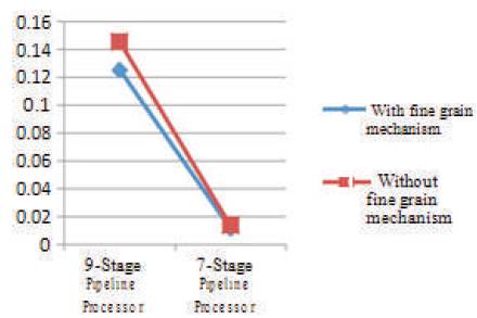
Figure 7. Power Consumption Result
To minimize the performance degradation associated with reduced power consumption, it needs to adjust the pipeline depth to a suitable depth for the current workload and program features. Fine grain mode prediction mechanism has been applied to predict suitable pipeline depth every several tens of cycles and change pipeline depth without incurring a large overhead. Also predicting a suitable pipeline depth using a processor counter such as a cache hit counter or an instruction counter can be performed. In this paper the fine grain mode mechanism is applied to 7-stage processor so that, it predicts the suitable pipeline depth for the variable stage pipeline processor, also analyzing the operation that should be performed in the processor. Compared to existing in proposed method 11% of power consumption has been reduced. Finally thus power consumption has been reduced by using fine grain mode mechanism for the processor and performance is increased.