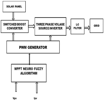
Figure 1. Proposed System of Block Diagram
This project is aimed at the implementation of a fuzzy based maximum power point tracking in transformerless gridconnected PV system along with reactive power compensation. A single diode model is used for PV array and simulation study is performed using Matlab. In the neuro-fuzzy logic controller, voltage and current are taken as inputs and the effective value of AC current corresponding to the maximum power point is the output. As a result, in addition to supplying voltage via the inverter without using transformer to compensate for reactive power not exceeding its power rating. This results in utilization of PV system at night and at periods of low irradiation. Rules relating the input and output of neuro-fuzzy logic controller are written and simulation is performed. A DC-DC Switched Z source Boost Converter is used for maintaining DC input to the inverter at various conditions of irradiation and temperature. Gating pulses to the inverter are generated by PI (Proportional integral) controller. Simulation model of a 1000 W solar panel is developed and the results are obtained with neuro-fuzzy logic controller for different irradiation and temperature conditions. Results show the effectiveness of the proposed method in utilizing the PV system. This project is implemented in Matlab simulation.
In the present trend, renewable energy sources are attractive choices for providing power in the places where an association with the utility network is either not possible or unduly costly. As electric distribution technology steps into next century, several trends have become noticeable which will modify the necessities of energy delivery. The ever increasing energy consumption, soaring value and exhaustible nature of fossil fuels, and also the worsening international environment have created enhanced interest in green power generation systems. Renewable sources have gained worldwide attention because of quick depletion of fossil fuels in conjunction with growing energy demand (Liu & Lai, 2007; Schenck et al., 2005). The energy harcested from renewable resources is called renewable energy, which is naturally replenished on a human timescale, such as sunlight, wind, rain, tides, waves, and geothermal heat. Renewable energy provides energy in four areas like: electricity generation, air and water heating/cooling, transportation, and rural (off-grid) energy services.
Sustainable power source springs from common procedures that are recharged never endingly (Huang et al., 2018). In its differed shapes, it gets directly from the sun, or from warmth produced profound among the planet. Encased inside the definition is power and warmth created from sunlight, wind, sea, hydro power, and biomass based energy assets, and bio-powers and substance component got from sustainable assets. Sustainable power source assets are crucial open doors for energy intensity existing over wide land territories, in qualification to energy source options that are engaged in an exceptionally limited scope of states. Prior to the era of coal during 19th century, almost all energy used has been renewably produced. Not a wonder, the famous use of renewable energy within the ancient style has been biomass to fuel fires, dates from 790,000 years past. Use of biomass for fireplace failed to become commonplace till several many thousands of years later, someday between 200,000 and 400,000 years past. Most likely the second oldest usage of renewable energy is harnessing the wind so as to drive ships over water (Zhang et al., 2017). This observation may be derived back from 7000 years, to ships on the river in the time of recorded history. The first sources of ancient renewable energy were human labour, animal power, water power, grain crushing windmills, conventional biomass, etc.
With the spreading apprehension of the nonrenewable sources of energy, the prices of fossil fuel are increasing constantly, damaging ecosystem and environment. The renewable energy global warming is seemly more promoted and is attaining more attention as designated to nonrenewable sources of energy. Solar system energy is the most acute and sustainable sources of energy, throughout the renewable sources of energy in comparison with the other source of energy resources such that wind, tidal, fuel cell, etc. Radiation from the sun (sunlight) is converted into electricity on a photovoltaic array. In gridconnected PV system, the PV system is linked together with grid by using boost converter and MPPT for control of coordination in grid system (Sreekanth et al., 2016). Gridconnected photovoltaic plants are being promoted for various applications in distributed power generation and for the efficient use of solar array power plants. Transmission line containing higher voltage with long distance is no longer compulsory as power is totally transferred by local renewable sources of power. The elevation of the connection of renewable energy sources of power to conventional AC systems is explained by An and Cha, (2013), and Shi et al., (2015).
PV power and transmitting to the grid are two unique sorts of components used in grid-connected solar plants with two levels to figure out. The system composition is specially designed for a PV array that converts solar radiation into DC power, a boost converter (DC to DC) to raise the PV array voltage level to a moderate DC voltage level, and a twolevel DC-to-AC inverter to convert DC power into AC power. Thus, in addition to supplying voltage from an inverter without a transformer, it is worth compensating for the reactive power (Itoh & Hayashi, 2009; Sravani & Kumar, 2016). The installed AC power of the inverter is boosted into the grid and used by local loads (Kyritsis et al., 2007; Zhu et al., 2014).
The computation of solar energy systems consists of photovoltaic (PV) installation, in which energy is exchanged in the public electricity grid or power can be provided exactly to electrical equipment. For the betterment of the efficiency of PV array in the photovoltaic system, there is requirement of power electronic conversion and also the reliability of system is needed. The power circuit contains a boost converter (high step-up), DC to DC converter and an inverter with multilevel to transform DC to AC in these systems, as the voltage of grid is pulsating (AC) in nature. The requirement of control circuit is to get constant (DC) voltage at output with PV systems output voltage at load side, and it is continuously varying in nature (Yang et al., 2013). This is the analysis of grid-connected solar power plant with DC boost converter using MPPT as shown in Figure 1.
Figure 1. Proposed System of Block Diagram
The sunlight is an eco-friendly and everlasting reliable energy source. The energy radiated from sun is received directly for power generation through photovoltaic system. One of the significant methodologies utilized from solar power is photovoltaic (PV) arrangement which is capable of converting sunlight into electricity using photovoltaic effect. The basic building block of photovoltaic modules is the solar cells. The efficiency of a PV module is determined by the material used in photovoltaic cells and the method used to assemble the solar cells into a module. In the conversion of sunlight to electric energy, solar modules have an efficiency of roughly 12-29%. Solar cells made of gallium arsenide have a maximum efficiency of 29%, while solar cells made of silicon have a maximum efficiency of 12-14%.
The most common silicon processes are mono-crystalline and polycrystalline. Because a conventional solar cell produces less than 2 W near 0.5 V, a solar panel is constructed by connecting a number of cells in series to get the requisite voltage. As a result, the panels are arranged in an array. The series connection of the arrays produces a higher output voltage. If the PV cell does not receive any solar radiation during the process, it becomes a p-n junction diode.
Due to the interaction of photons with the PV cell, pairs of electron holes are generated when solar radiation falls on the PV cell. The photon generated electron-hole pair is divided by the electric field produced by the cell junction, with electrons and holes drifting to the n and p regions of the cell, respectively. This movement generates a photocurrent that is mostly dependent on the intensity and wavelength of solar irradiation. If solar radiation does not fall on a PV cell, it becomes inactive and works as a p-n junction diode, as previously stated. PV cells do not generate current or voltage in this state. However, when cell is linked with an external large supply than cell voltage it produces a current ID which is called dark current as shown in Figure 2.
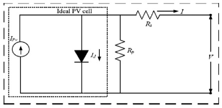
Figure 2. Equivalent Circuit of PV Cell
The power conversion PV system includes many series and parallel PV modules, a tracking controller, and power converters such as DC-DC converters and inverters. As a result, the DC voltage created can be amplified using a DC-DC converter and then converted to AC using an inverter. The PV panel should be chosen based on the load rating.
The PV model constitutes current sources, diode shunt resistance Rsh, series resistance Rs. Shunt resistance Rsh represent the cell surface leakage through the edges.
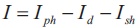
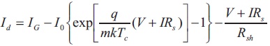
The total current I (Equation 1) is the difference of the light generated current Iph, diode current Id and current through Rsh.
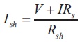
Diode current Id and shunt resistance current Ish is presented by Equations (2) and (3).
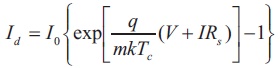
where,
m = Idealizing factor
K = Boltzmann constant
Tc = Absolute temperature of cell
q = Charge of electron
V = Potential across cell
I0 = Cell reverse saturation current
Usually shunt resistance Rsh in PV cells is high hence is  eliminated.
Hence,
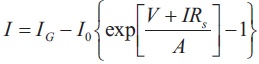
where, A = curve fitting parameter.

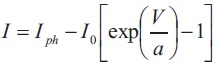
According to Figure 2, output current at standard test condition is,
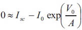
When PV cell is short circuited,
Only in ideal case, these Equations (5) and (6) are valid. Hence the equality is not accurate, Equation (6) is written as, Iph≈Isc
The photocurrent depends on both irradiance and temperature.
where, G = irradiance
Gref = irradiance at standard testing condition
The shunt resistance is usually high for all applications and hence eliminated by using 3 standard conditions.
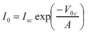
Open circuit voltage is I=0, V=Voc
Short circuit current is V=0, I=Isc
The voltage (Vmp) and current (Imp) at maximum power is explained by the following equations.
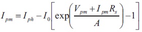
The value of -1 in the equation can be eliminated as it is very small compared to exponential term. Substituting (Iph) in Equation (8), we get,
Hence,
The Figures 3 and 4 show the IV and PV curves of single solar panel for different irradiance.
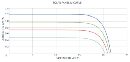
Figure 3. Single Solar Module IV Curve
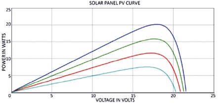
Figure 4. Single Solar Module PV Curve
The subfolders underneath the “Simulink” folder indicate the general classes of blocks available.
Blocks have zero to several input terminals and zero to several output terminals. Unused input terminals are indicated by a small open triangle. Unused output terminals are indicated by a small triangular point.
Lines transmit signals in the direction indicated by the arrow. Lines must always transmit signals from the output terminal of one block to the input terminal of another block. One exception to this is that a line can tap off another line. This sends the original signal to each of two (or more) destination blocks. Lines can never inject a signal into another line and lines must be combined through the use of summing junction. A signal can be either a scalar signal or a vector signal. For single-input, single-output systems, scalar signals, are generally used. For multi-input, multioutput systems, vector signals are often used, consisting of two or more scalar signals. The lines used to transmit scalar and vector signals are identical. Figure 5 shows the Matlab model of the proposed study. The type of signal carried by a line is determined by the blocks on either of the line as shown in Figure 6, 7, 8 and 9.
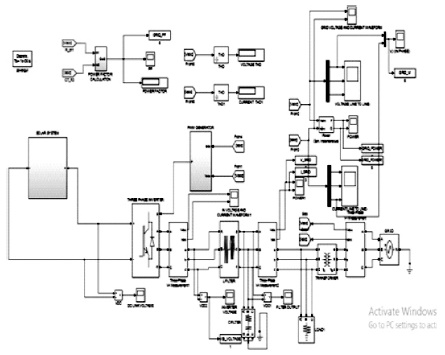
Figure 5. Matlab Model of the Design
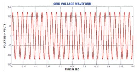
Figure 6. Grid Voltage Waveform
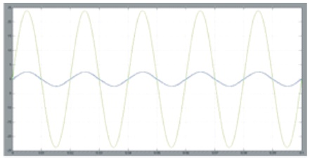
Figure 7. Grid Synchronization
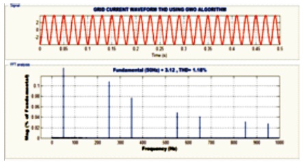
Figure 8. THD Waveform for Grid Current
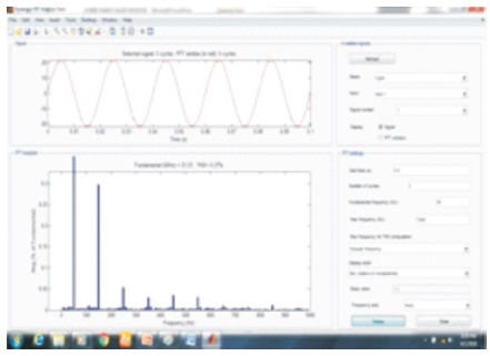
Figure 9. THD Waveform for Grid Voltage
Building the system model is then accomplished through a series of steps.
Each of these steps will be explained in detail using our example system. Once a system is built, simulations are run to analyze its behaviour.
This project presented a single phase grid-connected DC/AC inverter with reactive power (VAR) control for residential PV application. It has been shown that residential PV power generation has garnered much attention in today's demand for renewable energy. Grid interconnection standards such as IEEE-1547 are used to regulate the power quality of the local DR power injection. As a consequence, single phase, low power VSI's are commonly used for the interconnection between PV modules and the utility grid to ensure that the power quality meets grid standard. In addition, as more distributed resources such as local solar generation are integrated into the grid at the distribution level, there is a tendency for DR units to actively supply reactive power to the grid. Therefore, this work proposed a solution for the VSI to actively control the reactive power injecting to the grid. This leads to the main contribution of this work, which is the design of a low complexity grid synchronization method that does not rely on use of high performance control platforms for creating parallel and orthogonal component of the grid voltage in order to control the real and reactive power flow. The synchronization method inherently attenuates grid distortion and is immune to slight grid frequency variations. Meanwhile, due to the manufactures' guarantee on the life time of PV inverters, the VSI has been designed to use a small, more reliable, film type capacitor on the DC-link in a cost effective way while maintaining a good output power quality.