Figure 1. Simulation Model for DSTATCOM for Harmonic Voltage Reduction in Hybrid Grid (Benali et al., 2018)
Improved power quality is the driving capability for today's modern manufacturers. Consumer awareness regarding reliable power supply has risen enormously in the last decade. This has led to an additional impact in the development of small distributed generation (DG). Small isolated DG sets can feed local loads, leading to enhancement in the authenticity of power with low capital investment. These systems also increase importance in remote areas where transmission using overhead conductors or cables is unrealistic or prohibitive due to high cost and other circumstances. Small generation systems in rural areas, islands, hilly terrains, marine plants, aircraft, etc., can be efficiently used in developing countries too. However, these DG sets have to be de-rated if the induction motor loads are instantaneously started. One practical choice is to use DSTATCOM in a shunt structure with the central system to efficiently utilize the full capacity of producing sets. DSTATCOM consists of a voltage source converter (VSC), and it internally has the required capacitive and inductive reactive power. Its control is high-speed and can provide acceptable reactive power compensation to the system to which it is connected. The method of DSTATCOM for solving power quality problems due to voltage fall/dip, flickers, swell, etc., has been suggested. The purpose of DSTATCOM is to provide efficient voltage regulation at the point of standard coupling (PCC) and thus prevent significant voltage dips.
Several loads in the industry are inductive, like induction motors, ceiling fan, etc. Such cases of these inductive loads current drawn by the masses from the supply is insulant concerning the voltage (Hosseini & Ajami, 2002). The reactive power burden on the system will increase, which can increase losses in the distribution system and the capacity of active power flow through the distribution system gets reduced. Thanks to the advancement of power physics technology, nonlinear loads in the order are increasing, like rectifiers, inverters, uninterruptible power supply (UPS), computers, etc. These non-linear masses will cause the production of frequency elements of the currents in the system, which are not fundamental frequency elements. Therefore, due to such harmonic components of currents the quality of power gets affected (Jun et al., 2011). Furthermore, there is an unbalanced impact on the operation of the transformers and generator. The solution to power quality improvement is done using a custom power device (Bajpai & Dash, 2012) like DSTATCOM. DSTATCOM has been used to suppress the harmonics (Janaki et al., 2011) in the shunt current. With the proposed method, the reactive power from microgrids is controlled to mitigate the voltage change caused by the active power from the hybrid microgrid and simultaneously, the DSTATCOM is activated to suppress the harmonics originated from renewable power generators and integration of STATCOM (Kumar & Mishra, 2014). The energy storage device plays an essential role in improving the performance of the system. However, the DSTATCOM is an active power filter (APF) that reduces the high voltage stress across each power switch (Mahela & Shaik, 2016). To satisfy the demanded power with maximum utilization of renewable resources (Janaki et al., 2011), the tolerance of the supervising controller is applied in the AC/DC microgrid.
To investigate the compensation resulting from the operation of DSTATCOM and study the DSTATCOM to improve the power quality so that it maintains voltage magnitude approximately to nominal value by compensating the essential amount of current to the distribution system from the storage element through DSTATCOM.
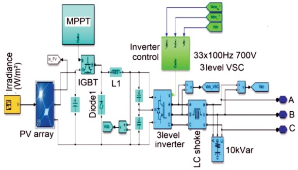
MATLAB model is designed for the distribution system. The Figure 1 shows the MATLAB model for the distribution system. In this system, the three-phase ideal source is supplying power to a nonlinear load. The nonlinear load is indicated by a three-phase diode rectifier module connected to resistor-inductor (R-L) load. The DSTATCOM is an IGBT based three-phase voltage source converter. This converter is controlled to supply needed reactive power and harmonic current into the system. To interface DSTATCOM to the distribution system, filter inductors are used. These inductors are used to limit circulating current flowing in the system. To control the amount of power flow from DSTATCOM is designed in simulation.
Figure 1. Simulation Model for DSTATCOM for Harmonic Voltage Reduction in Hybrid Grid (Benali et al., 2018)
A photovoltaic array (PV system) is an interconnection of modules, which in turn is made up of multiple PV cells in series or parallel. The power generated by a single module is not sufficient to meet the requirements of industrial applications, so modules are attached to form array to supply the load. In an array, the connection of the modules is identical to that of cells in a module. The modules in a PV array are primarily connected in series to reach the desired voltages; and the individual modules are then connected in parallel to concede the system to produce more current.
MPPT control has been used for MPPT measurement in this system. The P&O method has been used for the MPPT measurement of solar power. The MPPT method considers to automatically find the current IMPP or voltage VMPP at which a PV array should work to obtain the maximum output power PMPP under a delivered temperature and irradiance (Ahmed et al., 2007). Most of the MPPT methods respond to variations in both irradiance and temperature, but some are precisely more useful if the temperature is approximately constant (Dahono & Purwadi, 1995). Due to aging, most MPPT methods would automatically react to differences in the array, though some are open-loop and would require periodic finetuning. In our context, the module will typically be combined with a power converter that can differ the current expanding from the PV array to the load.
Module type: SunPower SPR-305-WHT
Number of cells per module: 96
Number of series-connected module per string: 9
Number of parallel strings: 40
The most commonly used MPPT algorithm is the P&O method. This algorithm uses a simple feedback preparation and little measured parameters. In this method, the module voltage is periodically given a perturbation and the conforming output power is compared with that at the preceding perturbing cycle (Ropp & Gonzalez, 2009). In this algorithm, an insignificant perturbation is introduced to the system. This perturbation reasons the power of the solar module numerous. Due to the perturbation when the power increases, the perturbation then continues in the same direction (Zouidi et al., 2008). Until peak power is reached, the potential in MPP will be zero until the next instantaneous reductions, after which, the perturbation will be reversed (Delghavi & Yazdani, 2009).
The conventional boost converter has only one equivalent inductor and only one equivalent output capacitor. This makes the input current time-varying and full of ripples. The theory of the boost converter is well documented (Akagi et al., 2017; Sen, 1999) and DC-DC boost converter model is shown in Figure 2. The proposed design is a multi inductor design with a firing circuit controlled by a phase-shifting algorithm in such a way that the system converter input current is held constant corresponding to the maximum power point of the solar array. The phase-shifting algorithm can be used in conjunction with any MPPT (Lee et al., 2005; Masood et al., 2010; Shen et al., 2010).
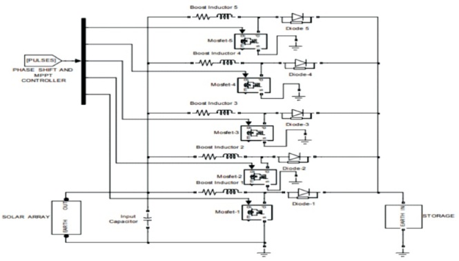
Figure 2. DC-DC Boost Converter Simulink Model
The HRES structure with proposed methodology is depicted in Figure 3. The presented HRES is identified as three groups and they are connected to DC bus commonly (Ghosh & Ledwich, 2012). It can be divided into two main groups in which first group has the renewable energy sources, solar PV system, which gives power to the DC bus. The second group provides the energy storage systems, battery, UC and FC, and it offers the durable electrical energy as well as the fast dynamic power regulation.
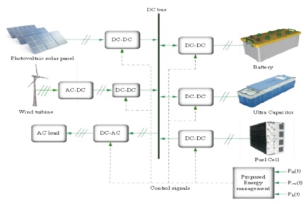
Figure 3. Structure of the HRES with Proposed Methodology
Various load has been applied in distribution network and the power balance has been controlled via DSTATCOM in the system. Here we can see the simulation design for various load.
2.6 Nonlinear Load
A load is estimated nonlinear if its impedance changes with the applied voltage, and the non-linear load circuit is shown in Figure 4. The changing impedance describes that the current drawn by the nonlinear load when connected to a sinusoidal voltage will not be sinusoidal (Akagi et al., 2017). These non-sinusoidal currents having the harmonic currents create voltage distortion to interact with the power distribution system impedance and it can affect both the distribution system equipment and the loads to which it is connected (Sen, 1999).
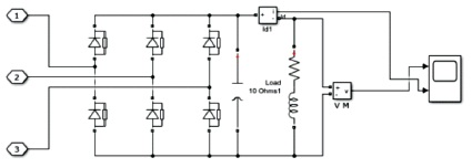
Figure 4. Nonlinear Load
In this hybrid DC microgrid, rectifier, buck, boost and bidirectional converters are power electronic interfaces which are employed to be responsible for voltage conversion. Pulse power load in the distribution network is shown in Figure 5. Also some of these converters have to control the power injection to the grid and follow the determined reference signals by the EMS. The uncontrolled rectifiers type are used. Hence low pass filters are necessary to modify the rectifiers output voltage quality, which is located between uncontrolled rectifiers and boost converters in this grid.
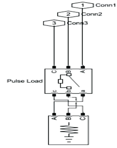
Figure 5. Pulse Power Load in the Distribution Network
Inductive loads, known as lagging loads or power factor loads, are AC loads which are predominantly inductive due to which when the current flows into the load the alternating current lags after the alternating voltage. Inductive load in the distribution network is illustrated in Figure 6.
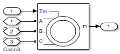
Figure 6. Inductive Load in the Distribution Network
Simulation activities of the proposed system are executed in MATLAB/Simulink to observe the performance of the system under various conditions such as without DSTATCOM, with DSTATCOM, and a supercapacitor supported DSTATCOM. These different cases are described independently. The variation of loading conditions with three phase fault is given in Table 1.
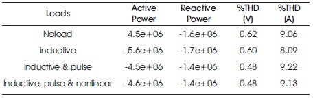
Table 1. Variation of Loading Conditions with Three-Phase Fault
Table 2 shows the same with three phase fault and DSTATCOM. The VSC control graph for load time is shown in Figure 7.
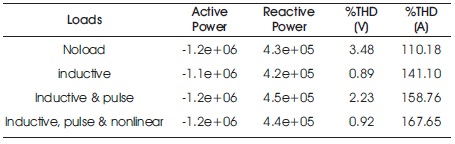
Table 2. Variation of Loading Conditions with Three-Phase Fault and DSTATCOM
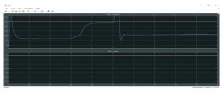
Figure 7. VSC Control Graph for Load Time
DSTATCOM has been modelled and simulated in MATLAB/Simulink environment (Yazdani & Iravani, 2010). The operation of DSTATCOM has been investigated for nonlinear load, pulse load and reactive load drive using distribution network transmission. The simulation shows the effectiveness of DSTATCOM in a distribution network. The simulation shows the performance of an inverter in compensating the reactive power when the supply voltage is not constant. The reactive current compensation is attained in no time during the increase and decrease in source voltage. The DSTATCOM responds well to the sudden change in the source voltage. The THD is also well below the IEEE standard, which reveals that the control algorithm performs well in eliminating the harmonics.
This paper proposes a new long term schedule for optimal placement and sizing of DSTATCOM in a hybrid distribution network using a nature-inspired renewable algorithm for obtaining minimization of power loss. The design and control of a DSTATCOM have been carried out for a threephase distribution system. A control algorithm based on correlation and cross-correlation function has been found suitable for generating the switching signals of DSTATCOM in a three-phase power system. In this project, algorithms are implemented for the operation of DSTATCOM to eliminate harmonics in source current due to nonlinear load, pulse load, and reactive load. The MATLAB simulation model is designed for all power loads, and simulation results are analyzed. This system is implemented and compared for harmonic elimination, power factor correction and tracking capability to maintain DC bus voltage. With the effect of source distortion, these three algorithms are analyzed. The next level in this research is to consider Microgrid as a system. It is essential to know more about how the sources interact with each other. More specifically, their relationship to each other needs to be defined. If all goes as anticipated and the Microgrid system is developed, the control of the order will likely be embedded within the electronics. It is possible to use specialized controllers to get a more stable response and to use each power source more efficiently. This should undoubtedly be researched and considered once the power sources interaction and relationship with each other and the mains have been defined. Other aspects that could be developed further are the original sources within the Microgrid.