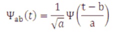
where,
a is scale/dilation co-efficient.
b is shifting/translation co-efficient
Ψ∞(t) is mother/descendant wavelet.
2.1 Types of Wavelet Transform
- Continuous Wavelet Transform (CWT)
- Discrete Wavelet Transform (DWT)
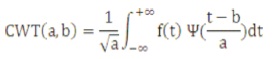
2.1.1 Continuous Wavelet Transform (CWT)
It calculates wavelet co-efficient at every possible scale and shift. Signal f(t) is defined by scalar product between Ψ∞(t) and f(t) as,
2.1.2 Discrete Wavelet Transform (DWT)
Wavelet transforms of sample waveforms are often obtained by implementing the DWT given by
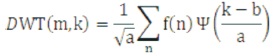
Ψ(n) is mother wavelet, f(n) is sampled function, a and b are functions of integer parameter k, k and m are integers. Both CWT and DWT are continuous-time frames, but DWT is preferred than CWT. CWT provides more information than required where as DWT provides only the specified information in both time and frequency domain. The implementation of DWT is simpler than CWT because it makes use of analysis method sufficiently, which are versatile to handle signals in terms of time-frequency localization.
For analyzing the transient phenomenon related with transmission line faults, DWT is very useful technique. DWT is implemented by filter bank technique referred to as Multiresolution analysis (MRA) which involves successive pair of high pass and low pass filters at each scaling stage of wavelet transform as shown in Figure 1. These filters produce two types of coefficients, low frequency component (approximation co-efficient (cA)) and high frequency component (detail coefficient (cD)) followed by dyadic decimation.
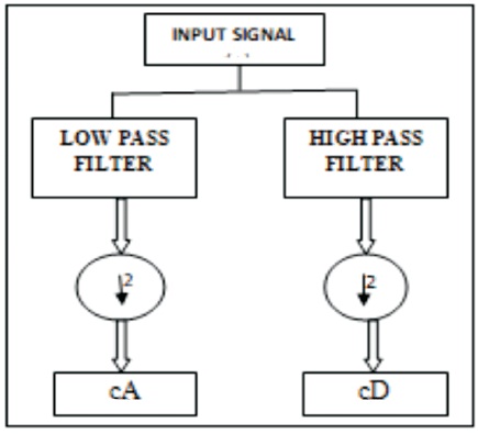
Figure 1. Discrete Wavelet Transform
MRA involves filtering of the input, which separates the frequency components present within the signal by passing it through a series of low pass filters (LPF) and high pass filters (HPF) as shown in Figure 2.
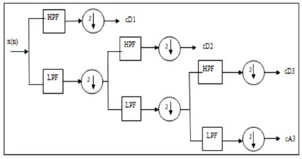
Figure 2. MRA Decomposition of Sampling Frequency
At each level, there are two types of co-efficient that are obtained from low pass filter, i.e., cA1 and cD1 of level 1 are outputs of the first LPF and HPF. Each time the signal passes through the low pass filters, it is down sampled by two for faster computation of the next level of co-efficient, i.e., cA1 is decomposed to urge next level of components cA2 and cD2 and so on.
Daubechies wavelet is employed for detecting low amplitude, short duration and quick decaying and oscillatory kinds of signals. Daubechies wavelet has many filters coefficient like Db4, Db6, Db8 and Db10. Fewer coefficient (Db4 and Db6) of the mother wavelet can reduce calculation time and also make the overall response faster. Higher Db (Db8 and Db10) means more filter coefficient are going to be processed which could influence the specified memory size and therefore the computational effort. Hence Db4 is chosen as the mother wavelet in this work. The choices of filter HPF (h) and LPF (g) co-efficient with four are called analysis by daubechies wavelet with four filter coefficient (Db4).
3. System Model
For verifying the proposed method and to research the applicability of specified algorithm, the IEEE 9 bus system model is taken into account for simulation. MATLAB/ Simulink software is employed for simulation purpose. The IEEE 9 bus system model is shown in Figure 3 and data is given in Table 1. It consists of three generators, three transformers, three loads and six transmission lines. The length of the each transmission line is 100 km.
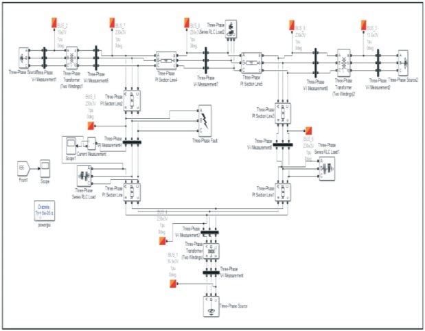
Figure 3. IEEE 9 Bus System Simulated Model
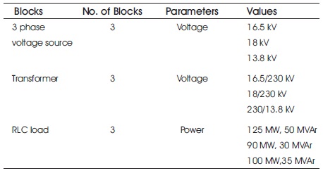
Table 1. IEEE 9 Bus System Data
4. Simulation Results
With the help of current measuring instrument, the current signals of all the three phases A, B and C are recorded. The recorded waveforms for normal operation and various fault conditions such as single line to ground fault, double line faults with or without ground and three phase fault are shown from Figure 4(a) to 4(e).
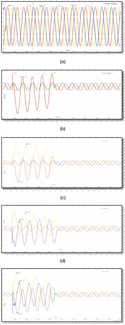
Figure 4. Current Signal (a) Without Fault: Normal Operation, (b) L-G Fault In Phase A, (c) L-L Fault In Phase A and B, (d) L-L-G Fault In Phase A and B, and (e) L-L-L Fault
5. Fault Detection Methodology
Wavelet transform is useful in analyzing the transient phenomenon related with the transmission line faults. Wavelet makes use of variable window length that automatically adapts to give appropriate resolution. Here a non-stationary signal is decomposed into low frequency and high frequency components and these are called as approximation and detail coefficients respectively. Figure 5 gives the algorithm for fault detection using DWT.
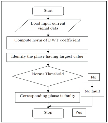
Figure 5. Flow Chart For Fault Identification
To detect the fault accurately, first obtain the current signals for all the three phases. These current signals are given as input to one-dimensional discrete wavelet transform available in the wavelet transform toolbox. Then using DWT with db4 as mother wavelet up to level six, the current signal is decomposed. The norm of DWT coefficients of current signal are obtained for various fault conditions. The approximate and detail coefficients are provided in the Figure 6.
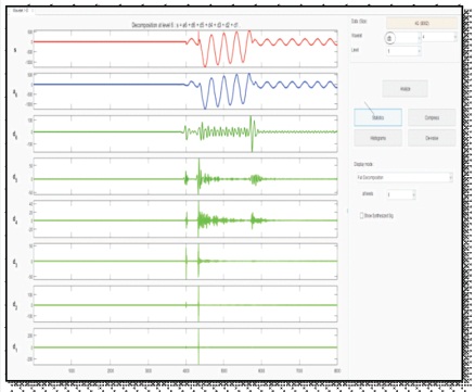
Figure 6. Approximate and Detail Coefficient Signal
Normal condition coefficients are taken as reference/ threshold values and coefficients of other faulty conditions are compared with threshold values. If the norm of DWT coefficient of particular current signal is less than the threshold value, then that line is considered as healthy. The corresponding phase is called to be faulty, if the magnitude of norm values is greater than the threshold values. This helps in detection and discrimination of fault from the other faults.
Table 2 shows calculated norm values of DWT approximation (cA) and detail coefficient (cD) of each phase current for normal and fault condition using daubechies wavelet (db4) upto sixth level decomposition with fault time of 0.08 second and simulation time of 0.2 second.
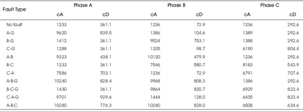
Table 2. Fault Detection Using Db4 Wavelet
6. Fault Classification Methodology
After the detection of faulty phases, it is important to classify the fault. The types of faults considered in the analysis are single phase to ground fault (L-G), phase to phase (L-L), two phase to ground (L-L-G) and three phase fault (L-L-L or L-L-L-G). Figure 7 gives the algorithm for fault classification.
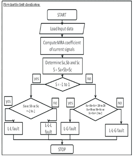
Figure 7. Flow Chart For Fault Classification
The fault signals are first simulated in MATLAB/Simulink and each phase current values are obtained. These phase current values are loaded as input to the multidimensional 1-D DWT in the wavelet toolbox. The signal is decomposed to sixth level using db4 wavelet. The MRA coefficient of current signals is shown in Figure 8.
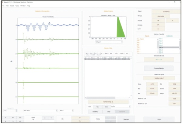
Figure 8. MRA Coefficients
The mean/summation of appropriate or detail coefficient of db4 wavelet transform of sixth level decomposition for each phase is considered as a parameter for the classification of fault. Then summation of sixth level decomposition detail coefficients of each phase A, B and C are calculated, i.e., Sa, Sb and Sc respectively as shown in Table 3. Later S is determined which is sum of mean of each phase detail coefficient (S= Sa+Sb+Sc).
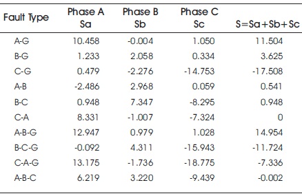
Table 3. Fault Classification Using Db4 Wavelet
- If S value is within the range of -1 to 1, then classify the fault as L-L or L-L-L fault, if not L-G or L-L-G fault.
- If Sa or Sb or Sc value is in the middle of -2 to 2, then the fault is L-L fault. Otherwise it is L-L-L fault.
- If sum of Sa, Sb and Sc is between -20 to 20 and Sa+Sb or Sb+Sc or Sc+Sa value is in the range of -2 to 2, then it is L-G fault. Otherwise the fault is L-L-G if Sa+Sb or Sb+Sc or Sc+Sa value is between -15 to 15.
Conclusion
Transmission line protection is an important issue in the power system engineering. In this paper, an effective algorithm to accurately identify and classify the transmission line faults is carried out using DWT with db4 as mother wavelet upto level six. The proposed scheme takes the pre fault and post fault signal of the three phase currents of IEEE 9 bus system. From the wavelet toolbox, the approximation and detailed coefficients are obtained and compared and summed up to identify and classify the faults. The simulation results shows that the proposed method has the ability of identifying and classifying the different types of faults quite accurately and efficiently and power system reliability can be maintained. Futhure for future research, finding the location of fault in the transmission line can be carried out.