(1)
This paper presents feedback linearization technique based Direct Power Control (DPC) algorithm for 3-phase Voltage Source Inverter (VSI). In order to make the controller design easy and independent of the operating point, the non-linear model of the VSI is transferred into linear model. The Direct Power Control - Space Vector Modulation (DPC-SVM) technique is adopted and the problem is formulated in DPC framework in which the constant switching frequency is maintained throughout the operation of the Inverter. A robust nonlinear controller for DPC-VSI applying Input-Output linearization (IOL) techniques is also discussed. To cancel the non linearities and to decouple the input control variables, the feedback linearization nonlinear technique is used. Great tracking capability with zero steady-state of the voltage loop has been achieved by zero-dynamic control. Also, there is no derivative calculation required and measurement of load current is not needed. The controller which is proposed in this paper has advantages of fast DC-bus voltage response, robust against parameter uncertainties and decoupled dynamical d-q current loops which provide wide operating range and fast transient responses. The validity of the technique has been verified through experimental setup which is compared with the traditional control. The results analysis shows that the use of feedback linearization control gives excellent transient response both during balanced and unbalanced load and with gird voltage.
The invention of advanced power semiconductor switches have motivated increasing attention in recent years towards Pulse-width Modulation based Voltage Source Inverter (VSI) (Lee et al., 2000; Niculescu et al., 2006). Compared to conventional inverter a three-phase Voltage Source Converter (VSC) has many advantages such as input currents nearer to sinusoidal, controlled input, constant DC bus voltage and bi-directional power flow capability with controlled active and reactive power (Azizi et al., 2005; Carbone & Scappatura, 2005). Also, low harmonic distortion of line current and input power factor regulation to unity. Direct Power Control (DPC) for the VSI has attracted the attention of many researchers. All these features make DPC-PWM-VSI systems suitable for connecting renewable sources to the main grid, especially on offshore wind farms (Abbas & Lehn, 2009; Du et al., 2005; Gonzalez-Hernandez et al., 2008). The research which has done till now is mostly on control point of view using small signal stability or linear models with compensation (Guedouani et al., 2007; Jeong & Song, 2007; Lee, 2003, Lu & Ooi, 2003; Rafiei et al., 2006; Wang, 2002; Zhou & Wang, 2002). The performance will be same and retained in any conditions such as limited operation range and large DC-bus capacitance (Koytiva et al., 2005). With linear control systems using multivariable controlled inputs and highly coupled nonlinearity of DPCPWM- VSI, it is very difficult to achieve ideal control. Over recent years, the research has taken place on non-linear control theories and developed a new theory called Input-Output Linearization (IOL) (Duarte-Mermoud et al., 2006; Guo-Qiang & Zhi-Xin, 2010; Petrzela & Hrubos, 2009). The main need of this nonlinear control method is to liberalize and decouple synchronous d-q axes dynamics in VSI. But it involves more mathematical calculations which make constrained use of this technique. However, with the development of floating point based Digital Signal Processor (DSP) and Advanced Control techniques the nonlinear differential-geometric technique based IOL has come into existence for nonlinear system control (Isidori, 1989; Slotine & Li, 1991).
Nonlinear controllers are able to effectively tackle the variations in operating points for a grid-connected inverter system to overcome the limitations of linear controllers. There are several existing and new research activities to design nonlinear controllers for grid-connected inverter systems. The feedback linearization (FBL) technique is the most widely used nonlinear control technique which cancels inherent nonlinearities using nonlinear coordinate transformation. An exact FBL technique is used to control the active power injection with the aim to enhance the dynamic stability of a three-phase grid-connected converter system where the model is mainly based on the dynamics of d-q axes currents. However, a three-phase grid-connected converter system is not always exactly linearized and hence, some unrealistic assumptions are required to design an exact feedback linearizing controller.
In the original DPC strategy (Noguchi et al., 1998), the conventional current control loops and PWM modulator are replaced by a lookup table control scheme to obtain fast transient responses. However, this scheme causes problem of variable switching frequency. Malinowski et al., (2004) Proposed the DPC Space Vector Modulation (DPC-SVM) providing the VSI with a constant switching frequency operation without sacrificing the original DPC performance.
Since the VSI dynamic model is nonlinear, controllers are conventionally designed using the linearized model of the VSI around an operating point. This leads to the dependence of the controller design on operating point. On the other hand the feedback linearization method transforms nonlinear systems into decoupled linear systems. This is the method applied for VSI (Lee, 2000; Malinowski et al., 2001), which results into fast transient responses in complete operating range. The complexity in the control algorithm makes it difficult to implement practically. Marzouki et al., 2010 and Phruksarangruk & Nungam, (2015) Proposed an improved method, which takes the energy stored in the output capacitor as state variable instead of DC bus voltage. Applying feedback linearization technique to state variables is much easy and simple process.
In this paper it is proposed to use the output power of the capacitor as state variable of the system and to that system feedback linearization is applied using DPC. The problem statement is defined and the experimental verification of the results has been done. From the results with the used control strategy, VSI provides a fast transient response which is independent of operating point.
The feedback linearization method is presented briefly and detailed description can be found (Duarte-Mermoud et al., 2006; Isidori, 1989; Petrzela & Hrubos, 2009) before going for the control schemes. This feedback linearization is used for nonlinear designs. The first step is to convert the nonlinear system into linear system (fully or partially), and use the well know powerful linear designs for control schemes. This method is completely different from the conventional linearization method. In feedback linearization method, the process takes place by exact state transformation of the system, whereas in conventional method it is carried by linear approximations of the system dynamics. It states that the original systems will be transformed into a simple equivalent form. Even though there are many different types of linearization methods, input output feedback linearization method is the best one.
Input-Output Feedback Linearization Technique is further classified into two types:1) Input-State Feedback Linearization and 2) Input-Output feedback Linearization. There are three rules for input-output feedback linearization. First rule is to derive output until input appears, second rule is to choose new control variable which reduces the tracking error and which eliminates nonlinearity and the third rule is to study the stability of internal dynamics of the system which cannot be observed in input-output linearization even though it is the part of the system. For an input-output system first a feedback linearization theory for multi variable systems is applied before applying nonlinear control to the PWM converter. The Multiple-Input & Multiple-Output (MIMO) nonlinear system is considered.

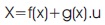
where x is an n×1 state vector, y is m×1 output vector, f (x) and h (x) are nth -order smooth vector fields, g(x) is an n×m matrix of smooth vector field columns gi, and u is the m×1 control input vector.
This approach helps us to obtain IOL of the Multi-Input Multi-Output system, which differentiates output y of the system till the input appears. It is needed to get the smallest derivatives of yi which is called as relative degree of that particular output. The smallest derivative of a particular output is expressed as follows.
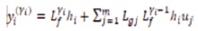
where LgjLfyi-1 hi≠ 0 for at least one in Equation (3) if the previously mentioned condition is complied. The Lie derivative for any scalar function of h is defined as Lfh =curl(h).f, thus, Lfi h =Lf Lfi-1 h =curl(Lfi-1h).f is defined recursively for any positive integer i .
When the process for each output state variable using equation (3) is completed then we obtain a differential equation as follows.
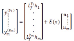
or equivalently,
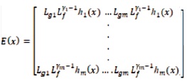
where the m×m decoupling matrix E(x) was defined as,
And then, if E(x) is non-singular, the new transformed system with IOL can now be written as,
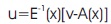
Where v is a dummy input vector. Now substitute equation (7) in equation (5) which results into a linear differential relation between output y and the new input v,
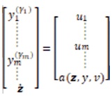
The above equation is an input-output linear differential relation. Each input vi affects its corresponding output (yi), and called as decoupled linear relation.
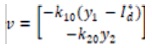
The tracking of the constant output reference is taken as y*= [y1*……..ym*]T, by setting the auxiliary feedback.


For some positive constants kij,i=1….,m; j=1…..γi, the ij closed-loop error dynamics is as follows.
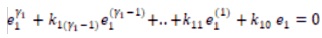
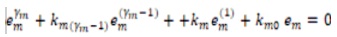
where,

and ei =yi -yj*, i=1…..m . Then choose the appropriate k to make the error dynamics stable. Now track y* reference by using linear pole placement technique.
The internal dynamic Equation (13) when tracking error e vanishes and is called the zero dynamics (Petrzela & Hrubos, 2009).

With Equations (11) and (12) one can stabilize the error dynamic by setting suitable linear state feedback.
Now the equilibrium stability of zero dynamics in equation (15) determines the equilibrium stability of the transformed system as in Equations (11), (12), and (13) under IQL laws in Equations (7), (11), and (19). When the zero dynamics is asymptotically stable, the nonlinear system is said to be in minimum-phase (Duarte-Mermoud et al. 2006).
The feedback line arization is particularly useful in power electronics to track the nonlinear problem, where a nonlinear process is transformed into a linear one by forcing the output to follow the input in a closed-loop fashion. Here the scheme of cascaded current control is derived based on IOL, where different types of two dummy output variables are used to control the dc-bus voltage of the VSI (Lee, 2003).
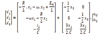
Specialized to the two-input two-output nonlinear state Equations (16), (17), and (18) characterizing the PWM VSI,we can substitute these equations into Equation (1) with n=3, m=2 to get.
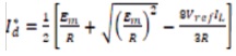
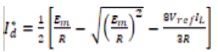
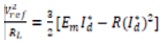
Applying the theory of IOL, it is natural to choose y= [x1 x2]T=[idiq]T as the dummy output. Obviously, the reference must be set to y*= [id0]T, when the q axis current d component x2 =0 under unity power factor condition. The dc-bus voltage x3 will be regulated to a desired value Vref indirectly when the output id tracks id*. From the steady- state solution of Equations (1), (2), and (3) with desired voltage reference Vref, one could determine the desired current command i*d (Suh et al., 2002), as follows.

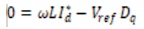
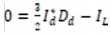
where Dd, Dq and IL =Vref/RL are the steady-state values of L the switching function and output load current respectively. From Equation (20) and (22) we can get the steady-state input line current,
As discussed in (Lee, 2003), the current reference command should choose the smaller one, so,
Applying the IOL method presented in previous section, the feedback equation is,
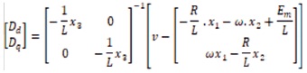
where,
Thus, we render the nonlinear VSI system in the linearized form as in Equation (11), (12), and (13) with z=x3 and the relative degrees γi =1, i=1,2........., substitute equations (25) and (26) to (13) to get the internal dynamics as,

Let the tracking error vector e→0, by x1 →Id, x2 → 0 and x3 → vref then the ideal energy conservative relation is as follows.
In the same time, with the equation (27) and (28), the zero dynamics between ac and dc side is,

The stability of the equilibrium point of the zero dynamics in Equation (29) determines the system stability. As discussed Lee (2003), both of roots x3 =±vref are stable. In actual control scheme the initial dc-bus voltage is positive, therefore, this strategy used here can achieve the desired dc-bus reference voltage vref. The block diagram of this current control scheme is shown in Figure 2, in which the VSC model is linearized and the crosscoupling between d and q current dynamics is removed.
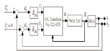
Figure 1. IOL fed current control loop for VSI
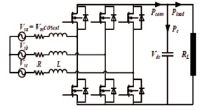
Figure 2. VSI Power Circuit
Almost in any industrial applications the converters of VSI have features of good power factor, low current harmonic distortion in input, and output dc voltage is variable reversibily. Normal rectifiers cannot meet the above requirement, but PWM rectifiers can meet those requirements. The VSI topology power circuit contains six controlled switches and input L filters. Input AC side contains three-phase symmetrical voltage sources with filtered inductor L and parasitic resistance R. It is connected to three-phase rectifier with six insulated IGBTs and reverse diodes in parallel.
The VSI under the experimental analysis is shown in Figure 2, where RL is a load resistance.
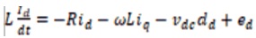
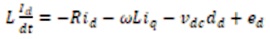
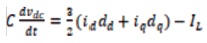
The (VSC) dynamic model in the synchronous rotating d-q frame can be expressed by equation (30) where the C is DC bus capacitor and R, L are resistance and inductance of the line reactor; ed, eq are supply voltages and id, iq, currents; the angular frequency of the line voltage is ω.
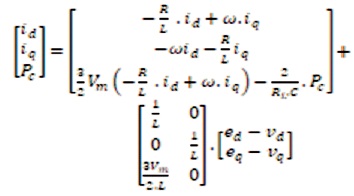
Where the control input voltages are vd, vq ; Note that power in the DC bus capacitor Pc is chosen as a state variable. By defining,
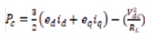


and using the power balance principle in figure 2, we obtain,

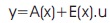
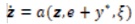
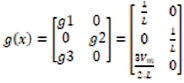
The plant under consideration using Feedback linearization technique is as follows,


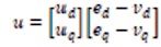
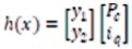
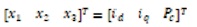
Where control inputs and outputs are defined as x, u and y state vectors. To directly control Pc we regulate V, so it is named as direct power control. The current iq used to control line side power factor, therefore, Pc and iq are chosen as the dummy outputs in equation (36).
Hence, from Equations (30) (35), and (36) we have,
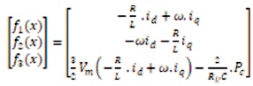
and ed =vm and eq =0
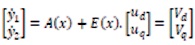
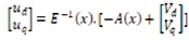
Feedback linearization technique is applied by differentiating the output, in equation (40) only once and the control inputs show up. The intermediate inputs Vd, Vq are defined by linear control technique and applied to the input and output. We then have,


When choosing the modulation it is important to consider following things: Minimization of load current harmonics and switching frequency and providing uniform switching frequency for all switiching devices and a balancd DC Capacitor voltage. There are several different PWM methods. Here, some of the most common modulation topologies will be discussed.
Different PWM approaches have the same goal, that is to reduce the THD of the current. To get lower THD, the switching frequency can be increased, which gives the required RMS values of sinusoidal output voltages and frequency. By switching ON and OFF of the pulses, the pulses with same amplitude and different widths can be obtained. These pulses produce the output sinusoidal waveform. The simple method to generate the pulses is by using Sine PWM, which is carried by comparing the triangular waveform with the sine waveform. When the reference sine wave is larger than carrier triangular wave, then PWM signal is switched ON:1, and otherwise the PWM signal is switched OFF:0.
The sine PWM is the most commonly used method but however it has big disadvantage of low magnitude of output voltage. Then the Space Vector Pulse Width Modulation (SVPWM) technique came into existence to overcome the drawback of SPWM. Depending upon the level of the inverter, different switching sequences are generated. The SVPWM technique provides unique switching states and can be applied for all types of multilevel inverters (Diode clamped, Cascaded, Capacitor clamped). The three nearest vectors forming the triangle will provide the duty cycle giving the desired reference voltage (Vref). SVPWM technique gives good utilization of DC link voltage with less current ripples and easy implementation. SVPWM technique has 15% higher voltage utilization thean SPWM technique. This is used for application of inverters in high voltage, such as renewable voltage generation. But as the number of level increases, the complexity increases. It becomes difficult to determine the level and find balance between losses. Therefore FBL method is applied to get the linear system and DC-link voltage controller is designed using classical linear control theory. The linearization input-output feedback technique is applied for various applications such as Dc-link PWM voltage control, uninterruptible power systems (UPS).
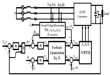
Figure 3. Block diagram of DPC with Feedback Linearization Technique
The proposed method is validated, and the experiment has been performed on a power board where FBL algorithm, the SVPWM algorithm and the PLL block are implemented. The actual operation of the IGBT PWM inverter was tested on a small prototype. The parameters for the PWM inverter and gains of controllers are shown in Table 1.
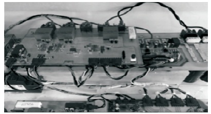
Figure 4. Setup for Experimental Analysis
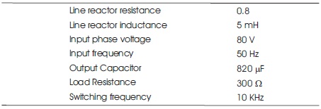
Table 1. System Parameters
Figure 5 shows DC bus voltage step response with 300 V to 350 V variation in reference. Figure 6 shows the DC bus voltage changes with 300 V to 150 V load changes. Figure 7 shows phase voltage and phase current from AC side.
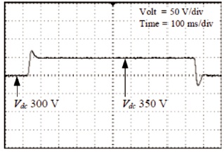
Figure 5. DC Bus Voltage Fast Transient Response
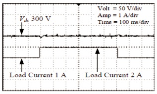
Figure 6. Change in Voltage of DC Bus when the Load Changes (The Load Current is Doubled)
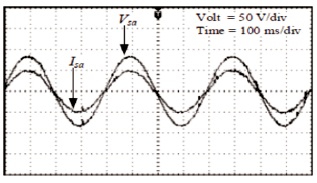
Figure 7. Phase Voltage and Current AC-Side
The gains of the PI controller are determined based on the P gain of the proposed FL method. The P gain of PI controllers is set at double.
To observe the transient performance, we can also apply 750 W loads during the entire experiment, then an additional 2.25 kW load is applied abruptly for 300 ms. Because the source voltage at the laboratory is distorted, the 5th and 7th harmonic current controllers are added to the basic current controller for both the PI and FL control methods. The DC-link voltage is disturbed about 2.7 V and overshoots are observed. The DC-link voltage is varied about 1.5 V and recovered rapidly to the reference value without overshoot. To observe the tracking performance, the reference of the DC-link voltage is changed in step from 320 V to 360 V.
We can track performance of PI and the proposed methods, respectively. In PI control, ξ is varied from 0.707 to 1.5. It is observed that overshoots still exist. On the other hand, the proposed method shows good performances without overshoot and steady state error. As the load changes, it has been observed that the capacitor and grid currents are varied and the phase of the currents are jumped. We can also see the waveforms of the grid voltage and harmonic spectrum of the grid current when FL is applied. The grid currents are controlled by sinusoid but the grid voltage is distorted. If we carry out the harmonic analysis of PI and FL methods, both of them show good results less than 1.4%. However, FL gives better performance in attenuating the switching ripples since damping resisters are not used.
When the converter operates at unity power factor then the current and voltage are in phase with each other. The experiment is carried out to get the several output voltages and the output voltages are presented. The results obtained clearly says, that the application of linear feedback technique does not depend on the operating point.
The feedback linearization control method implements an exact feedback control law. However, changes in the nonlinear load and system parameters in an actual power grid usually reduces the precision of the control and affect the harmonic compensating performance of the active power filter and it is used to implement the regulation of voltage in the DC side.
The FBL based DPC for VSI has been presented. The investigations of VSI with a resistive load in synchronous d-q reference frame have been described. The power in the output capacitor, Pc and the q-axis current are chosen as the outputs for the feedback linearization with which the complexity of algorithm is reduced which leads to constant decoupling matrix. Fast transient responses results because of the replacement of d-axis current by P . c The SVM based control with FBL is used which has an advantage of designing the controller with constant switching frequency and independent of the operating point. The results of experimental analysis shows that there is a fast step change in voltage for a step load change, which suggests the size reduction in output capacitor and also indicates that the VSI performances are virtually the same regardless of operating points. However, feedback linearizing controllers are used to control only the active power injection into the grid. It is now mandatory to inject reactive power into the grid through all VSI-interfaced generating sources. Moreover, the implementation of feedback linearizing controllers requires the exact parametric knowledge of grid-connected inverter systems and hence, the performances of these controllers are very sensitive to the variations in parameters.
A three-phase grid-connected inverter system is not always exactly linearized and hence, some unrealistic assumptions are required to design an exact feedback linearizing controller. So we can adopt partial FBL technique which overcomes the limitations of the exact FBL. We can also select the nonlinear adaptive back stepping control scheme which is one of the promising alternative solutions to overcome the limitations of the existing DPC with LUT, model predictive controllers, and SMCs. In an adaptive back stepping control approach, all system parameters can be considered as completely unknown as it can dynamically estimate these unknown parameters through adaptation laws. The other method we can choose is feedback linearization based sliding mode control using a fuzzy controller. A novel integral sliding mode controller with feedback linearization fuzzy control self-tuning is used to implement DC side voltage regulation and to reduce the THD of the supply current. However the simulation results have not shown here, still there is a strong bond between simulation and experimental results of the aforementioned methods. We can carry out the simulation of the above experimental setup with different methods of feedback linearization in MATLAB/Simulink environment.
I pay my sincere thanks to my research supervisors and the entire teaching staff, research scholars and laboratory staff at the Department of Electrical and Electronics Engineering, JNTUH College of Engineering, Hyderabad, for their continuous and tremendous support in conducting the experimental analysis and in publishing this work.
The authors have no conflicts of interest to declare.