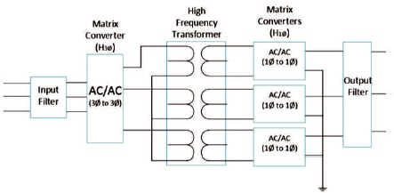
Figure 1. Matrix Converter based High Frequency Power Electronic Transformer Layout
This paper presents the concepts of three phase matrix converter based power electronic transformer for electric traction applications. The proposed high frequency Power Electronic Transformer (PET) will regulate the voltage level of the crossing train. The power electronic transformer with three phase matrix converter is used to step up frequency at the primary side and single phase matrix converter is to step down frequency at the secondary side for catenary. Power Electronic Transformer has several advantages over conventional solid state 50 Hz transformer. The control technique adopted is Space Vector Modulation (SVM) Technique for three phase matrix converter and Sinusoidal Pulse Width Modulation (SVM) for single phase matrix converter. The results of the Power Electronic Transformer along with the filters have been presented in this paper. The proposed topology has been implemented in the MATLAB/SIMULINK software and the desired results of the converter topology were verified.
This paper is based on the power electronic transformer device, which consists of power electronic converters at both the primary and secondary sides of the transformer. The high frequency transformer steps down the voltage to the catenary voltage from grid voltage level of 66/110/132/220 kV to the catenary voltage of 25 kV. The secondary voltage of transformer having 1 kHz frequency is stepped down to 50 Hz by single phase matrix converter connecting to the catenary completing the circuitary. With the several electrification systems, this project has been motivated. The layout of the project is depicted in the Figure 1.
Figure 1. Matrix Converter based High Frequency Power Electronic Transformer Layout
The required voltage level to the catenary is 25 kV and 50 Hz specifications, but due to the improper configurations of the traction transformer, and poor regulation at the substation, the voltage requirements are varying from 18 kV to 30 kV approximately, which is not a complete desired performance and serves as an disadvantage to the solid state transformer. Power electronic transformer can regulate the voltage levels and posses power quality improvement. Low frequencies will be operated for the heavy bulky transformers and the frequency of the operation increases whereas, the size of the transformer decreases considerably and this is the main motivation behind the power electronic high frequency transformer to be installed in the electric traction substations. Transformer oil can cause considerable damage to the device when caught on fire but High Frequency power electronic transformer does not suffer with this problem, hence making risk free environment. Hence power electronic transformer can be installed in the traction substation to overcome the interruptions caused by the solid state transformers at the substations.
A high frequency power electronic transformer is operated under high frequency say preferably greater than 1kHz of frequency posses several advantages when compared with the conventional solid state low frequency transformer which generally operates at 50 Hz (Casadei, Serra, Tani, & Zarri, 2002). The main advantages of high frequency PET include its very reduced size, reduced volume of the transformer, reduced cost, copper saving, reduced losses etc (Chen, Lipo, & Fitzgerald, 1996). Hence it is efficient and economical for the adoption of high frequency transformer for the specified applications (Nguyen, Lee, & Chun, 2010). To acquire the high frequency input to the transformer a three phase matrix converter has been adopted in order to step up the frequency greater than 1kHz at the primary side of the transformer as the input available to the traction transformer through the utility grid was 50Hz frequency (Kolar, Friedli, Rodriguez, & Wheeler, 2011; Casadei, Serra, & Tani, 1998). Hence, a power electronic converter which step up the frequency to the higher frequencies to feed the transformer is required and for this purpose three phase matrix converter has been adopted due to its several advantages compared to the conventional DC link converter (Hojabri, Mokhtari, & Chang, 2012).
A Three phase matrix converter is a device which converts AC voltage of one frequency to another desired frequency directly without any intermediate stage and the conversion process is shown in the Figure 2. It is a direct AC-AC converter without the use of bulky capacitor compared to the conventional DC link converter.
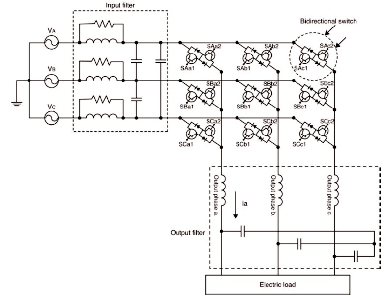
Figure 2. Three Phase Matrix Converter
Three phase matrix converter posses several advantages over the other converters which includes its bi-directional power flow capability, output voltage and frequency controllability, simplified control algorithm, high frequency switching capability, input power factor control with appropriate control technique, reduced requirement of the switches for power conversion from AC to AC etc.
It is a device which consists of 9 bi-directional switches connecting input and output circuits as required for the direct AC to AC power conversion. Three phase matrix converter in this paper converts input voltage of low frequency to the same voltage of higher frequency. It is a device which guarantees the output variable desired frequency. It acts as a substitute for the PWM voltage rectifier. TPMC is sensitive to the input voltage disturbances. TPMC gives sinusoidal output and input waveforms with almost minimum higher order harmonics and no-sub harmonics which serves an advantage to the converter and compatible design of the filters. Despite of having several advantages it suffers from the drawback of its maximum input-output voltage transfer ratio of 87% for sinusoidal input and output waveforms.
TPMC consists of 9 bi-directional switches which consists of two IGBT's along with anti parallel diodes connected in anti-parallel in configuration. The anti-parallel diodes serves the purpose of reverse voltage blocking for the switch shown in the Figure 3. Theoritically along with the 9 switches in the converter, the converter can have 2 power 9 of 9 states (2 ) i.e., 512 number of possible states the converter can experience. But for the proper operation of the matrix converter, there are two mandatory constraints imposed on it which is as follows. These constraints are mandated assuming the loads to be of inductive in nature.
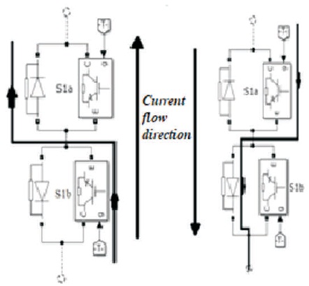
Figure 3. Bi-directional IGBT Switch Topology
Taking into consideration the above two constraints, matrix converter is having 27 active switching states for power conversion. The above constraints imply that only one switch is to be switched ON at any time instant and no two switches are to be switched ON at the same time of instant for safer operation of the matrix converter.
Three phase matrix converter also suffers from the commutation problem. Hence proper strategy has been implemented to avoid commutation problem.
The control technique adopted for the three phase matrix converter is space vector modulation technique which is based on the duty cycle approach among the various modulation techniques adopted for the three phase matrix converter for modulation. Space vector pulse width modulation technique, indirect SVM technique, alesinaventurini modulation, optimum AV method, scalar modulation techniques are few examples of them.
SVM technique possess various merits including simple control strategy, simple algorithm, higher switching, input power factor control capability, wide range of frequency variations etc. In this technique, the reference voltage and current as well are divided into six sectors of reference as shown in the Figures 4 and 5. With an assumption that the switching frequency is much greater than the input frequency. With the space vector modulation technique variable voltage of desired magnitude and frequency can be obtained by varying the switching periods of the matrix converter switches by appropriate reference vector. The reference vector rotates the circular trajectory and it is synthesized by the space vectors and the corresponding voltage magnitude is derived shown in the Figures 6 and 7.
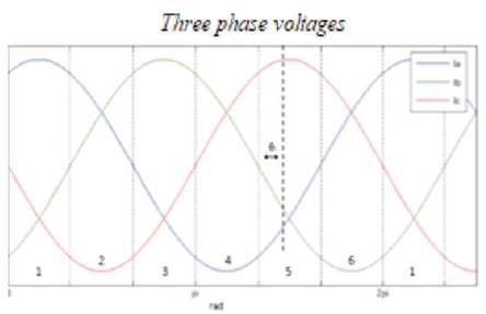
Figure 4. Line to Line Output Voltage Vector
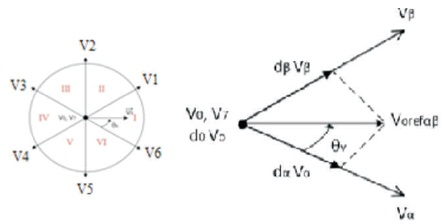
Figure 5. Obtaining Reference Vector
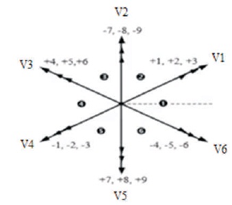
Figure 6. Voltage Vector
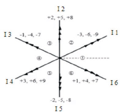
Figure 7. Current Vector
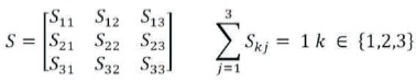
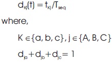
Let dkj be the duty cycle of the switch Skj, defined as
The same analogy is applied for the current vector as well. Vector modulation is done on both the references of voltage and current as well. Addition of current vector modulation gives the input power factor correction ability to the converter. It reduces the phase angle difference of 30 degrees between input voltage and current by taking the reference current vector in the modulation by selecting the switching states to the switches taking into consideration of the input power factor.
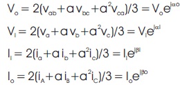
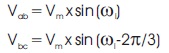
SVM technique treats the three phase quantities as the single quantity and transforms the three phase quantities into single as mentioned in equations (2) and (3).
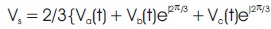
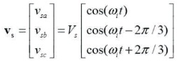
Where, va, vb, vc are the three phase input voltages which are displaced at 120o displacement. ωi be the input angular frequency Vs be the output voltage space vector. From the above equations, the reference voltage and current vectors are calculated and applied to the converter.
Voltage and current vectors are calculated by the phase angle through the circular trajectory. Output voltage angle, input current angle and modulation index are taken into consideration which are obtained from the phase angle, voltage and current vectors for calculation of the duty cycles for the switches. The duty cycles are obtained from the below mentioned equations.
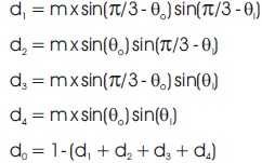
The duty cycles obtained from the vector and angle consideration is being compared with the high frequency saw tooth waveform shown in the Figure 8. Among any of the four duty cycles, whichever is greater than the reference wave, that duty cycle with the corresponding voltage and current vector is applied to the matrix converter switching states. Whereas, the duty cycles mentioned in the Table 1 are less than the reference wave, a zero vector state is in operation for the matrix converter (Nguyen & Lee, 2014; Durán, Riveros, Barrero, Guzmán, & Prieto, 2012).
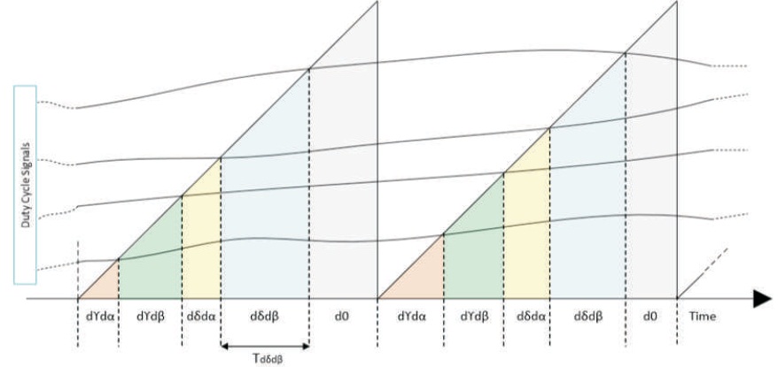
Figure 8. Comparison of Reference Wave with the Duty Cycles
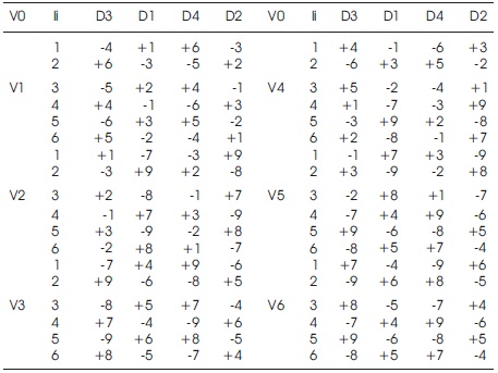
Table 1. Selection of Duty Cycles
Hence, for the matrix converter to step up the frequency, output voltage vector rotates the circular trajectory with the desired output frequency. For the matrix converter, the possible 18 switching states are assigned for a particular duty cycle with respect to the current vector (Busse, Erdman, Kerkman, Schlegel, & Skibinski, 1997). For the appropriate voltage and current vector with their frequencies may or may not be different, the matrix converter will undergo a particular state of conduction, giving the desired output frequency undergoing 18 active and 3 zero states.
A high frequency transformer has the several advantages of having reduced size and volume, reduced looses, low cost etc. The emf equation of a transformer is,
E = 4.44 x flux x frequency x TN
As per the equation, for a constant voltage and flux density, frequency is inversely proportional to the area of cross section of the core. So,
Area of cross-section of core = 1/Frequency
To avoid hysteresis losses at higher frequencies, ferrite core is used. If the frequency is increased with the constant supply voltage, eddy current losses are uneffected.
Mathematical modelling of high frequency transformer: The analysis of the power electronic transformer is based on the voltage parameters. Let Vab, Vbc, Vca be the three phase voltages with the peak voltage Vm and the input m angular frequency of ωi.
A single phase matrix converter is a device which converts the single phase input voltage at fixed frequency to the output voltage of desired frequency as shown in the Figure 9. A single phase matrix converter can serve the purpose of universal converter by performing the functions of chopper, rectifier, cyclo-converter, and inverter. It has four switches for the operation of the cyclo-converter. A switch consists of the two IGBT's connected with the anti-parallel diodes connected in anti-parallel. The anti-parallel diode serves the purpose of reverse voltage blocking and for conduction of current.
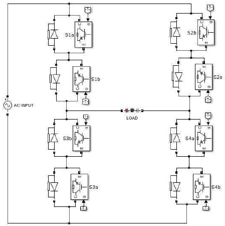
Figure 9. Single Phase Matrix Converter
A sinusoidal pulse width modulation technique is a widely used technique for the modulation. A sinusoidal wave is being compared with the reference wave for the pulse generation to the switches shown in the Figure 10. The duration and time delay for the pulses are calculated based on the desired frequency for the matrix converter (Erdman, Kerkman, Schlegel, & Skibinski, 1996).
In order to generate the pulses for the single phase matrix converter MATLAB /Simulink software is used.
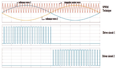
Figure 10. SPWM Technique
The simulation block which has been implemented in the MATLAB/Simulink Software has been depicted in the Figure 11.
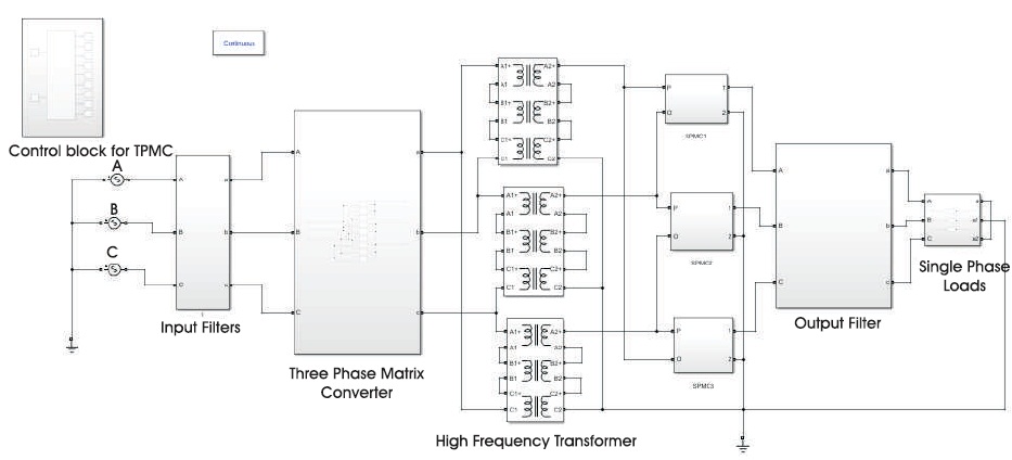
Figure 11. Simplified Schematic of the SST Model
The results obtained in the MATLAB/Simulink software have been depicted in the following Figures 12 to 16. Figures 12 and 13 depicts the voltage and current vector and duty cycles obtained. Figure 14 depicts the output voltage of three phase matrix converter. Figure 15 depicts the pulses generated from the SPWM. Figures 16 and 17 depicts the final output voltage and current obtained from the single phase matrix converter and the total harmonic distortion of the output voltage which is obtained as less than 5% of the value.
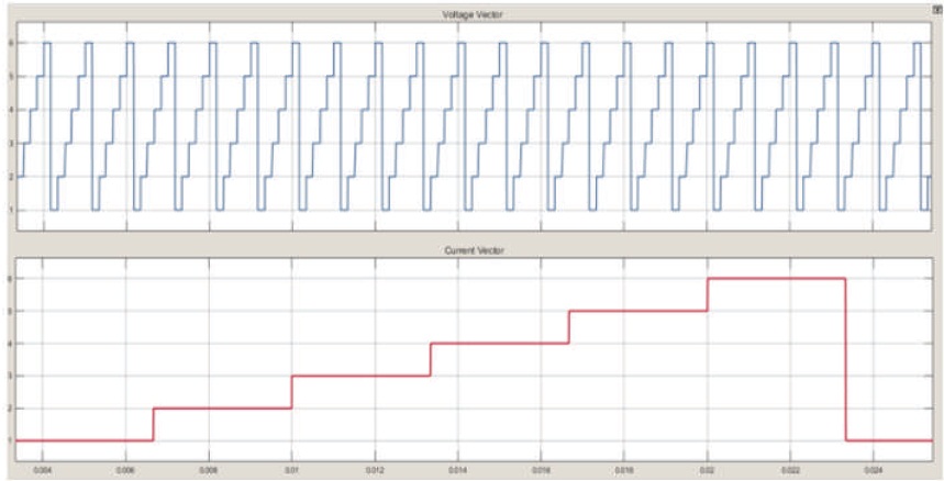
Figure 12. Current and Voltage Vector
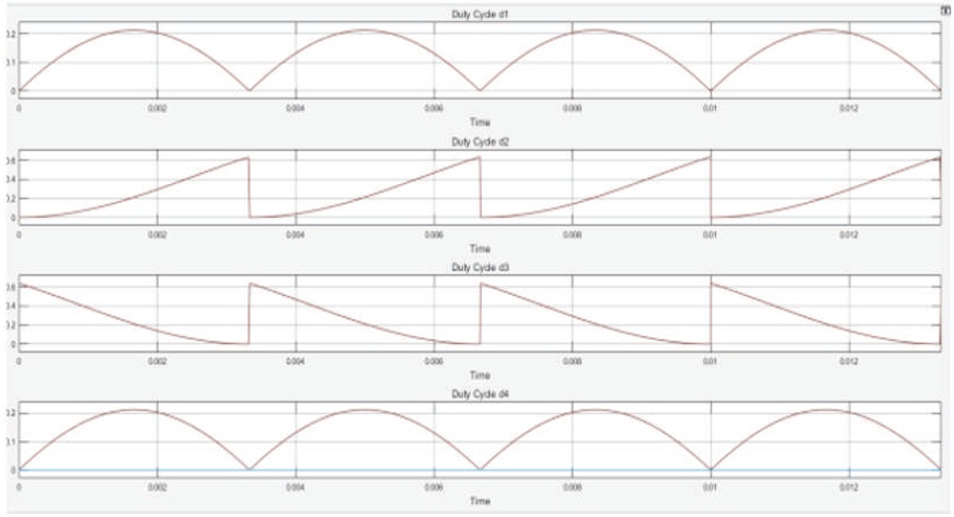
Figure 13. Duty Cycles
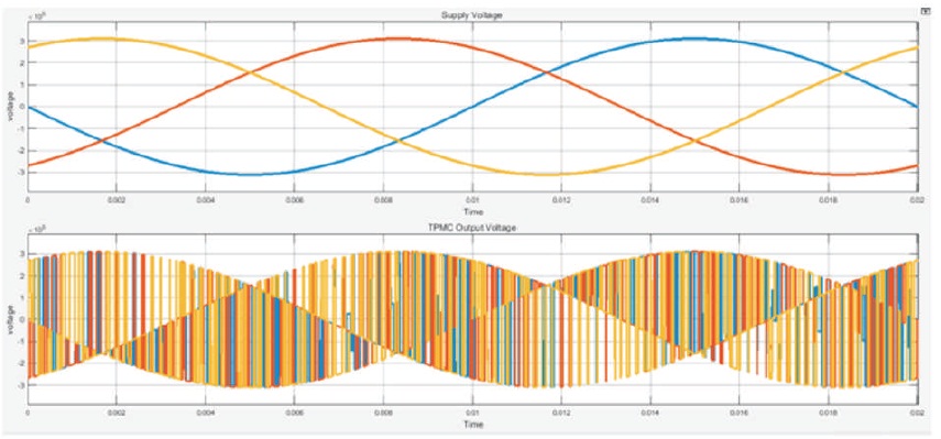
Figure 14. Input and Output Voltage Vector
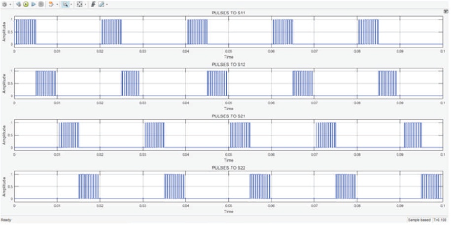
Figure 15. Generation of Pulses using SPWM to Single Phase Matrix Converter
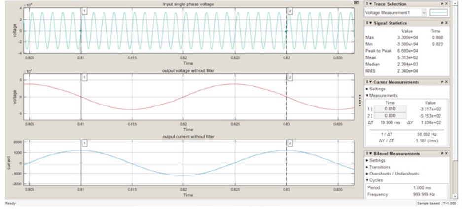
Figure 16. Output Single Phase Voltage and Current
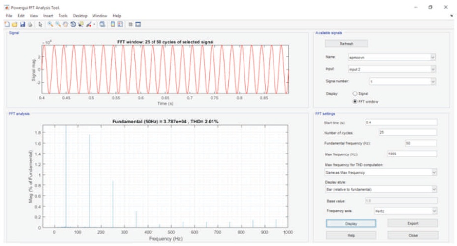
Figure 17. THD of Output Voltage <5%
The sinusoidal single phase output of the single phase matrix converter contains a total harmonic distortion of less than 5% of the total harmonic content with respect to the fundamental frequency which is depicted in the Figure 17. In order to achieve the better harmonic elimination of the output waveform of the converter any appropriate cost effective filters can be employed. For the preferable lesser harmonic content different appropriate control technique for the single phase matrix converter can be employed. The dominant third harmonic frequency can be eliminated by the delta configuration of the secondary side of the three single phase transformers. The frequency of the operation of the high frequency transformer can be selected based on the switching pattern of the three phase matrix converter, the selection of the type of switches employed and its withstanding capability.
A matrix converter based high frequency power electronic transformer with both three phase at the primary and single phase at the secondary of transformer has been simulated in the MATLAB/Simulink software and the results have been presented in this paper. The modulation technique used in this paper is space vector modulation. The IGBT's based matrix converter is implemented in this paper with appropriate switching combinations.
I take this opportunity to extend my profound thanks and deep sense of gratitude to God and my family for giving me the opportunity and strength along with patience to undertake this work. I am also grateful to our professors for the kind encouragement and constant support extended in completion of this work. I am also thankful to all those who have incidentally helped me, through their valuable guidance, co-operation and unstinted support during the course of my project.