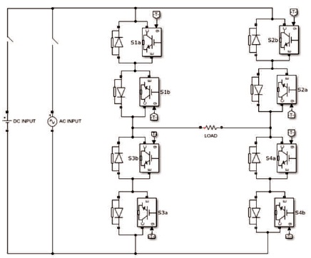
Figure 1. Single Phase Matrix Converter
This paper presents the concept of single phase matrix converter as an universal converter for high frequency step down operation. Matrix converter implemented as an rectifier, chopper, inverter, and cyclo-converter for a high frequency step down has been presented in this paper. This will reduce the need for the new or an extra converter requirement. The technique used for the implementation of the proposed topology was sinusoidal pulse width modulation technique. This paper verifies the four possible conversion processes, such as AC-DC, DC-DC, DC-AC, and AC-AC from a high frequency input to the desired low frequency output by the single phase matrix converter alone. The results of the four conversion topologies along with the filter has been presented in this paper. The proposed topology has been implemented in the Matlab / Simulink software and the desired results for each of the converter topology has been verified.
A Matrix converter is a direct AC-AC converter without any intermediate conversion process in it and without the requirement of the bulky capacitor. It is the most versatile converter (Zuckerberger, Weinstock, & Alexandrovitz, 1997). The desired amplitude and frequency can been obtained using matrix converter. Sinusoidal input and output voltage and current waveforms, inherent regenerative capability, bi-directional power flow, high switching capabilities, absence of capacitor, and controllable input power factor are the main advantages of the matrix converter, which makes it more advantageous (Ahirrao, Gaware, Kakade, Kharade, Chawda, 2014) compared to the conventional converters. It can step up/step down the frequency as per the requirement. When compared with the conventional converters, the size of the matrix converter reduces because of the elimination of the capacitor for the conversion process. Matrix converter is an array of bidirectional switches whose switching states can be represented in the form of an matrix as depicted in Figure 2 and hence the name matrix converter. With the bi-directional switch topology in it, it is capable for bi-directional power flow through it. Power conversion requirements have become more essential now-a-days. Precisely, AC and DC conversion has been used saperately at both the AC and DC loads. Single phase matrix converter has been introduced by Zukerberger et al. (1997). A single converter that can perform both the conversion processes has not been implemented. Matrix converter can be used for the purpose of conversion of both the AC and DC conversion simultaneously at both the AC and DC loads making it a unique advantage.
Single phase matrix converter consists of two legs and four bi-directional switches. As no monolithic bi-directional switches are available and are still under research, two IGBTs connected anti-parallel to it with a diode across it performs the function of the bi-directional switch (Sneha & Sajin, 2013). Each switch has been represented with '1' or '0' , which represents the state of the switch. State '1' represents the ON state of the switch whereas state '0' represents the OFF state of the switch in the matrix converter circuit (Satish, Konathala, & Kiran, 2014). The circuit of the single phase matrix converter has been depicted in Figure 1. IGBT; s has the combined advantages of the both BJT and MOSFET. The bi-directional switches are capable of conducting bi-directional current flow and capable of blocking voltage.
Figure 1. Single Phase Matrix Converter
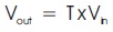
The transfer function of the single phase matrix converter has been represented as 'T', input voltage as 'Vin' and output voltage as 'Vout'. The input voltage and output voltage of the matrix converter can be related using the transfer function 'T'.The relation is represented as follows,
The switching states of the single phase matrix converter is represented as 'S' in the form of an matrix, which is represented as follows,
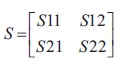
Figure 2 represents the bi-directional switch operation at the positive and negative direction of current flow (Deshpande & Jain, 2017). When the positive current flows through the switch, then the switch S1a conducts and when the negative current flows through the switch, the switch S1b conducts.
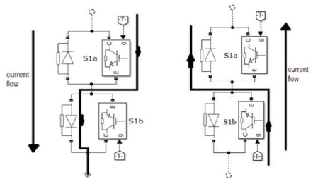
Figure 2. Bi-Directional Switch
The four possible switching states of the single phase matrix converter has been depicted in Table 1.
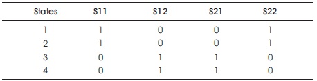
Table 1. Switching States of SPMC
The switching pulses to the single phase matrix converter is obtained using sinusoidal pulse width modulation technique, in which the desired output frequency and magnitude of the voltage can be obtained.
A rectifier is an converter which converts the input AC voltage or current into output DC voltage or current (Holmes & Lipo, 1989). Single phase matrix converter performs as an rectifier with its two states of operation as depicted in Figure 3.
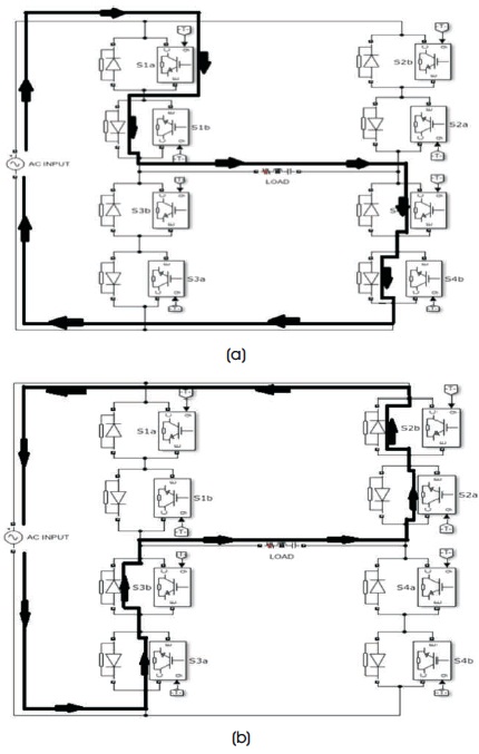
Figure 3. SPMC as Rectifier (a) Mode 1 (b) Mode 2
A chopper is a device which converters the input DC voltage or current to the DC output voltage or current (Ozturk & Onbilgin, 2018). For a single phase matrix converter to perform as an chopper, it undergoes mode 1 (Shashikanth, Sreenivasulu, & Kumar, 2015) operation as depicted in Figure 4.
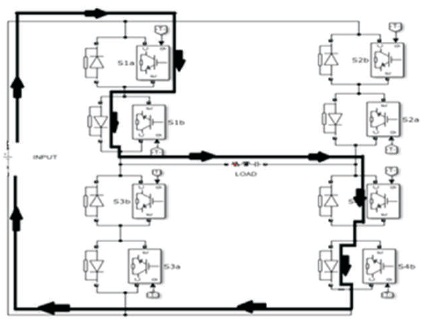
Figure 4. SPMC as Chopper
A cyclo-converter is an converter which converts the AC input voltage or current at one frequency into AC output voltage or current at desired or other frequency level (Srikanth & Kamakotti, 2017). For a single phase matrix converter to perform the operation of an cyclo-converter, it undergoes four modes of operation as depicted in Figure 5.
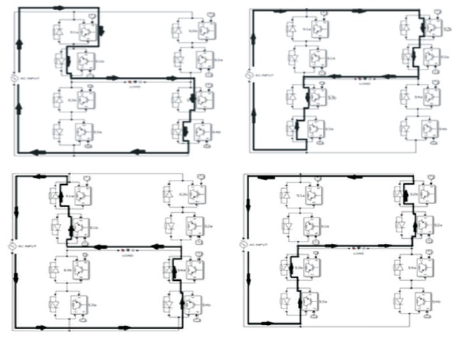
Figure 5. SPMC as a Cyclo-Converter
An inverter is an converter which converts the DC input voltage or current into AC output voltage or current. For a single phase matrix converter to perform the inverter operation, it undergoes two modes of operation as depicted in Figure 6.
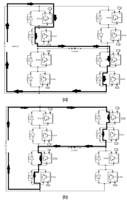
Figure 6. SPMC as Inverter (a) Mode 1 (b) Mode 2
The sinusoidal pulse width modulation technique is one of the efficient modulation strategies employed for the converters among the various modulation techniques (Kolar, Friedli, Rodriguez, & Wheeler, 2011). It consists of the two waves to be compared called a reference wave and carrier wave. The two waves are compared and a pulse is generated at the crossing points of both the waves (Sneha & Sajin, 2013). The reference wave in this sinusoidal pulse width modulation technique is the sinusoidal wave with the frequency of it to be desired as per the output frequency whereas the carrier wave is the triangular wave. The amplitude of the output voltage waveform depends on the ratio of the amplitude of both the reference and carrier waves, which is termed as the modulation index.

The simulation is performed in the Matlab / Simulink software for an input of 230 V,1000 Hz with R-load. Figure 7 shows the simulink model of the SPMC as an rectifier and its output.
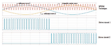
Figure 7. SPWM Technique
Figure 8 depicts the simulink model of the single phase matrix converter as the chopper along with its results.
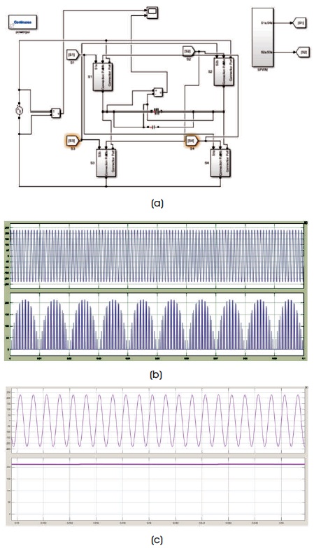
Figure 8. SPMC as Rectifier Output (a) SPMC as Rectifier Simulink Model (b) Output of a Rectifier without Filter Stepping Down 1000 Hz to 50 Hz (c) with Capacitor Filter
Figure 9 depicts the simulink model and the output of the SPMC as an cyclo-converter stepping down the input frequency of 1000 Hz to 50 Hz
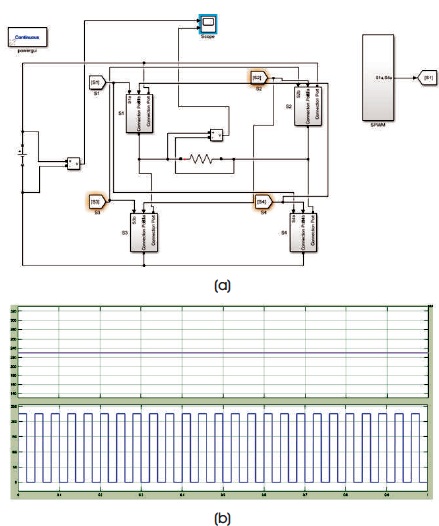
Figure 9. SPMC as Chopper (a) SPMC as Chopper Simulink Model (b) Output of SPMC as Chopper
Figure 10 depicts the simulink model and results of SPMC as an inverter.
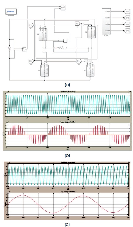
Figure 10. SPMC as Cyclo-Converter (a) Simulink Model of SPMC as Cyclo-Converter (b) Output of SPMC as Cyclo-Converter Step-Down of 1000 Hz to 50 Hz without Filter (c) Output with Filter Stepping Down of 1 KHz to 50 Hz
The output of the single phase matrix converter as an universal converter has been depicted in Figure 11. In this paper, the output results of the rectifier has been filtered out for the 50 Hz frequency from the 1000 Hz input and can be stepped down to any desired frequency with the sinusoidal pulse width modulation technique.
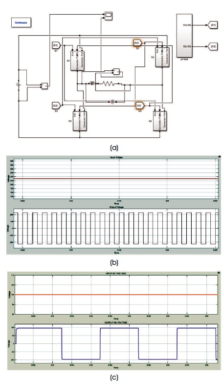
Figure 11. SPMC as Inverter (a) Simulink Model of SPMC as Inverter (b) Output of SPMC as Inverter for 1000 Hz (c) Output of SPMC as inverter for 50 Hz
For matrix converter as a cyclo-converter, input of high frequency say 1000 Hz is taken and stepped down to 50 Hz and it has been verified in Matlab/Simulink software and any range of frequencies can be adopted with the suitable design of the appropriate filter and as per the applications. For matrix converter as an inverter, a high frequency output has been verified using Matlab/Simulink software and the desired frequency can be adopted as per the application.
On comparision with the other converter topologies, matrix converter alone can be adopted as a universal converter with monolithic bidirectional switches without any intermediate conversion process unlike DC link converter, where AC power has been converted into AC power as a two stage process with a capacitor in between, which is not involved in the matrix converter and it converts the AC power directly into AC power with bi-directional switches. Matrix converter also provides sinusoidal input and output waveforms with minimal harmonics and input power factor can also be controlled using appropriate conversion techniques. Matrix converter has minimal energy storage requirements compared with the other converters.
It is observed that the single phase matrix converter can perform the four conversion processes, such as rectifier, inverter, chopper, and cyclo-converter operations referring to the universal converter operation with a high frequency input for the single phase matrix converter, stepping down to an desired low frequency output along with the rectified output with the filters employed at the output of the single phase matrix converter. The control technique employed for the conversion process is sinusoidal pulse width modulation technique and it is implied that any of the modulation technique can be used for the better and any modified required output. Hence, it can be concluded that the single phase matrix converter alone can be considered for the purpose of power conversion at both the AC and DC loads and also for an high frequency input. The results obtained for the each conversion topology has been verified in the Matlab/Simulink software.
I take this opportunity to extend my profound thanks and deep sense of gratitude to God and my family for giving me the opportunity and strength along with patience to undertake this work. I am also grateful to our professors for the kind encouragement and constant support extended in completion of this work. I am also thankful to all those who have incidentally helped me, through their valuable guidance, co-operation, and unstinted support during the course of my project.