Figure 1. Structure of DPFC [10]
The requirement of electricity demand has been growing day-to-day. Due to this, the transmission lines become overloaded. So that, it is very essential to monitor the flow of power within the standard limits and the safety operation. A new and cost effectual voltage source converter based FACTS converter has been proposed to control the transmission power flow. in this paper, Distributed Power Flow Controller is used to control the transmission power flow. The main objective of this work is to eliminate the low-frequency oscillations by proper designing of damping controller in DPFC. In order to explore the parameters, PI controller and fuzzy logic controllers are used. After comparing the results it can be proved that the Distributed-PFC with the advantageous design can efficiently improve the performance of the system more effectively when compared with other control techniques.
Low-frequency oscillations arise in the power systems due to the existence of interconnection between them. Also if any fault occurs in the transmission line, then due to that fault, one of the generator windings gets damaged. When it is either stator or rotor, the synchronization is not possible within the generator, then due to this speed deviations occur. Also due to the existence of fault in the line, the voltage in the line gets reduced and overcurrents flow through the line. Due to these two drawbacks, the electrical power of the transmission line gets reduced. In order to improve the output power by overcoming these two drawbacks here, FACTS device along with fuzzy logic controller is presented in this paper. These oscillations lie within the range of 0.4-3 Hz, if these oscillations are not damped using the controller they keep on increasing the magnitude till loss-of-synchronism results. So as to overcome this problem, PSSs (Power-System Stabilizers) [2] are used effectively in order to eliminate these oscillations.
But these stabilizers are incapable of controlling the oscillations so that in order to prevail over these difficulties, FACTS controllers are used. The basic initiative of FACTStechnology is to improve stability and reliability of the interconnected systems [6]. When compared with all other FACTS controllers, the UPFC is treated as the best one, but due to its complexity and cost, this device is not widely adopted [7]. To overcome these drawbacks, recently another controller named DPFC has been proposed which gives better control capabilities. This device offers greater reliability as well as low cost. The main objective is to eliminate the low-frequency oscillations by designing an oscillation damping-controller which is used in Distributed- PFC [10]. In order to explore the parameters of the damping-controller, PI controller and fuzzy logic controllers are used and these are presented in this paper. Here current-injection model is used in DPFC for analysing the behaviour of low-frequency oscillations.
The objectives of the work include the following.
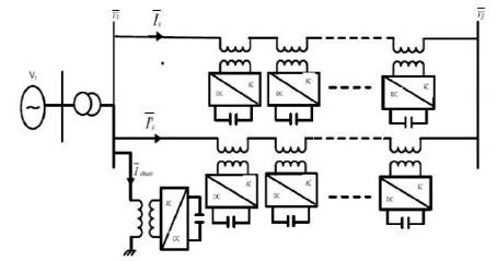
The basic structure of DPFC is shown in below Figure 1 consists of two converters, namely shunt and series converters [12], [14]. Here shunt converter acts as a STATCOM (shunt compensator) and multiple numbers of series converters are placed in series to a transmission line. Here SSSC (Static Synchronous Series Compensator) acts as a series compensator. In case of UPFC, there is a presence of common DC connection in the middle of the two converters and due to the existence of the DC link, many failures occur which causes damage to the entire converter [5]. But in DPFC, the DC link is eliminated between the converters, due to this many failures are avoided in the transmission line.
Figure 1. Structure of DPFC [10]
DPFC primarily includes two converters, one is shunt and the other is series converter. Both these converters act separately without any connection between them, whereas in case of UPFC, there is an existence of a DC capacitor which links both these converters. Suppose if any failure occurs in one of the controllers, then it affects the whole device and due to this, the power supply may get interrupted.
In order to overcome these type of drawbacks, a new device so called DPFC is proposed in this paper. Here real power is exchanged easily all the way through the converters’ AC terminals. Interconnection exists among the AC-terminals of shunt as well as series converters. Compared to the Unified PFC, the Distributed PFC offers better control capabilities in controlling the system parameters like line-impedances, load angles, system currents and also controlling the power oscillations [3], [13].
So as to examine the-impact of shunt as well as series converters in the power-systems efficiently, suitable representations of the devices are evaluated which are shown in Figure 2, the current in the shunt-converter is represented as Ishunt .
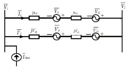
Figure 2. Equallent Circuit of DPFC [10]
The current equation is written as, Ishunt =It +Iq .
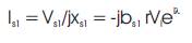
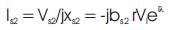
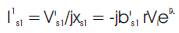
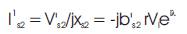
This current is in-phase with Vi, and the current Iq is in- quadrature with Vq . The voltage sources Vs1’ , Vs2’ , V's1 , V'2 has been replaced in its place of series converters. The Xs1’ , Xs2’ , X's1 , X's2 are reactance of the parallel transmissions lines. The magnitude as well as the phase-angle of the seriesconverters is often controllable, we are considering the same values [1], [9] in this paper.
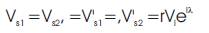
where r is the magnitude and λ is the phase-angle with respect to Vi correspondingly. Figure 3 represents voltage source in series with reactance that is converted to current source in parallel with reactances.
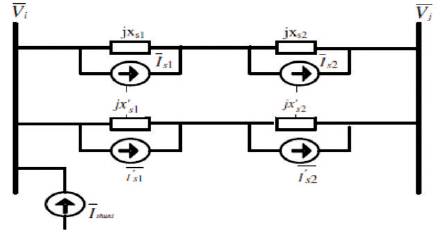
Figure 3. Conversion of DPFC Voltage Sources to Current Sources [10]

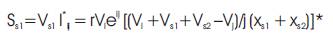
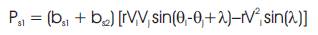
The real power that is supplied through the shunt currentsource is calculated as shown in below:

Neglect the DPFC losses,

The apparent power supplied by the series converter Vs1 can be calculated as follows:


Here a PI controller has been used, DC-link voltage is measured at the regular periods and it is to be compared with the reference voltage values that are generated from the controller. Error signal that is derived is given to the controller. In order to make sure that, whether the shuntactive power filter is capable of supplying the real power to the series-active power filter, a boundary limit is set to the controller output. The basic model of SATCOM that is used in UPFC is placed in shunt to the transmission line by using the step-down transformer. The main purpose of STATCOM is to monitor the bus voltage-magnitudes of the system [8].
There are two fuzzy-inference systems which are employed in the Fuzzy-Logic Toolbox, they are Mamdani and Sugenotype systems. Both of these are used in the fuzzy logic controller in order to get required output from the system. After comparing the results obtained from both the controllers it has been proven that, Mamdani type fuzzycontroller gives improved results as that of the sugeno controller. In addition to this, to obtain improved performance characteristics when compared with the PIcontroller, all the co-efficients must be optimized. Due to this, the complexity in the controller may get increased. Therefore, the computational time may also get increased. Finally, due to this, it cannot be applied in real time applications [4]. The basic fuzzy-controller is shown in the below Figure 4, the control-action is to be found from evaluating the simple linguistic-rules. The fuzzy-controller comprises of four blocks, namely fuzzification, defuzzification, knowledge-base, and inferencemechanisms. The knowledge-base block is designed in order to attain better responses during some of the disturbances. Fuzzification block is used to convert crisp inputs that are given to the system into fuzzy outputs. And these outputs are given to the defuzzification block which will again convert fuzzy outputs to crisp outputs. Inference mechanism consists of different set of rules which are used to solve a problem to obtain a better solution compared with PI controller [11].
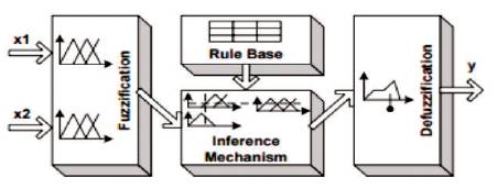
Figure 4. Block Diagram of Fuzzy Controller
The proposed control-scheme for the Distributed PFC is calculated through the computer-simulation in MATLAB or Simulink. For PI as well as fuzzy controllers, simulation-studies are conducted so as to calculate the stoutness of the intended damping-controller.
In this circumstances, a six-cycle 3-phase fault is considered and this fault takes place at t=1.5 sec, at the centre one of the transmission-line is cleared with the permanent-tripping of the faulted-portion. The speeddeviation characteristics of generator under nominal; light; and under the heavy-loading conditions are represented in Figure 5.
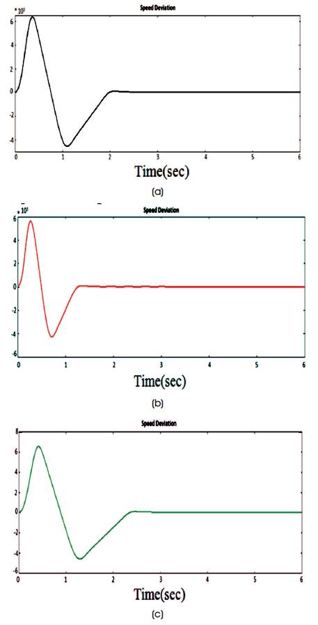
Figure 5. Dynamic Responses for Speed Deviations at (a) Normal, (b) Light, (c) Heavy Load Conditions with PI Controller
In addition, Figure 6 represents generator output-power; internal voltage-variations; excitation voltage-deviation with PI as well as Fuzzy-based controllers under nominal loading-conditions. The figures clearly represent the good quality damping-effect of the additional controller shown in Figure 7 as well as Figure 8.
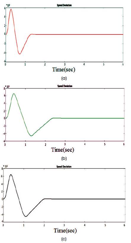
Figure 6. Dynamic responses for Speed Deviations at (a) Normal, (b) Light, (c) Heavy Load Conditions with Fuzzy Controller
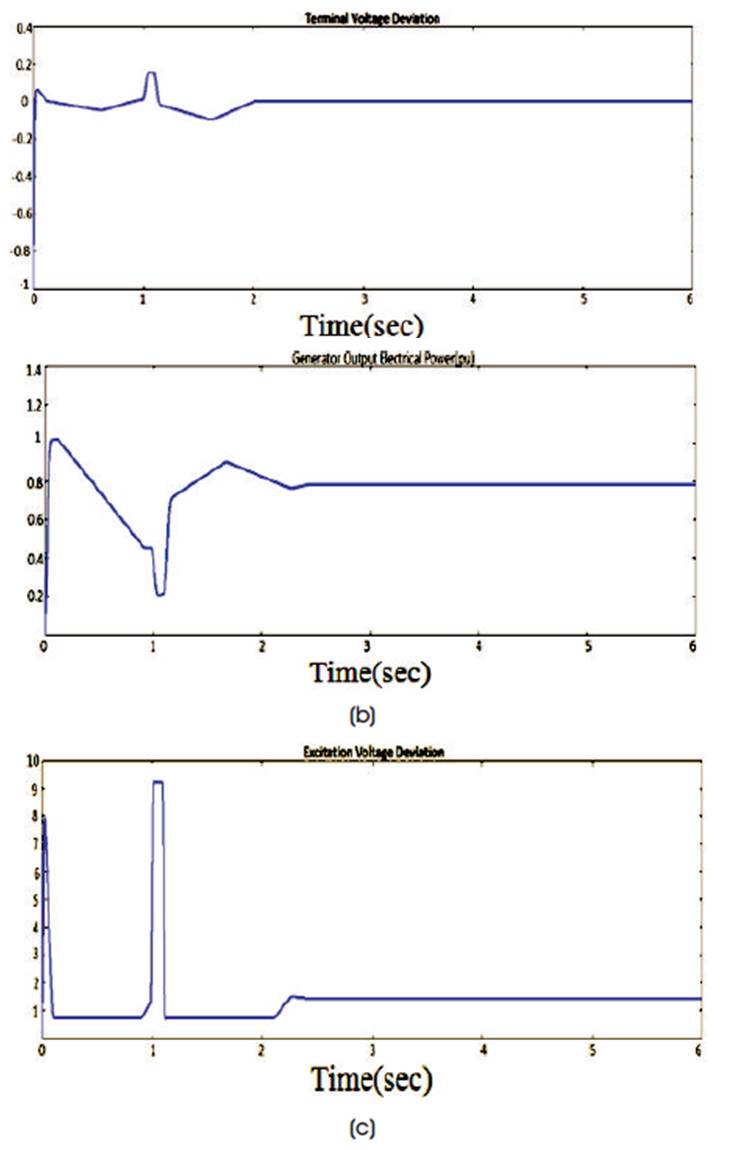
Figure 7. Dynamic Responses at Nominal Loading (a) Terminal Voltage Deviation, (b) Output Electrical Power, (c) Excitation Voltage with PI Controller
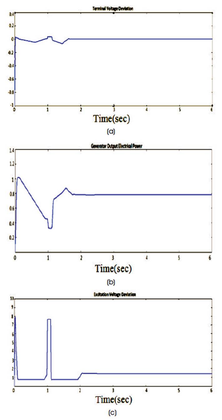
Figure 8. Dynamic Responses at Nominal Loading (a) Terminal Voltage Deviation, (b) Output Electrical Power, (c) Excitation Voltage with Fuzzy Controller
Here two-bus system is used to damp out the deviations effectively and it can be implemented in real time in transmission systems.
In order to control the reactive power as well as real power flow through the line and to offer sufficient damping controllers, this work analyzed to control voltage, speed deviations, and the electrical output power in the transmission line under different fault conditions. The simulation model of the DPFC is realized by using the MATLAB /SIMULINK software. The performance characteristics are compared by placing PI and fuzzy controllers in the DPFC system. By observing the results it has been proved that the characteristics obtained by the insertion of fuzzy controller are improved.