
Table 1. IEEE format representations
Fused Multiply Add (FMA) units generally reduce delay in the overall circuit and also make it efficient in terms of energy in arithmetic operations. In this paper, the authors present an effective implementation of MFMA (Modified FMA) using pipelining by decreasing the delay compared to the parallel processing of the module. This MFMA uses two desperate Massif which are connected using pipelining. The final operation performed is A*B+C*D+F*G+H*I, parallel processing just implements unto A*B+C*D. The clock limiting stage for both these operations is involved in normalization stage and rounding stage. This paper is related to floating point calculations. Floating point calculations involve, a standard format for representing floating point numbers. The standard format for representing floating point numbers is IEEE 754- 2008.This floating point representation is used here. In this paper the pipelining implementation is mainly related to speed, i.e., delay of the circuit. This paper can be designed using trilogy HDL or VHDL and is simulated and synthesized in XILINX ISE 10.1 of FPGA.
The primarily introduced accumulation principle architecture was MAC. MAC stands for Multiply- Accumulate Unit. MAC was used in many commercial and general purpose processors in early days. But MAC is only used to perform arithmetic operations, this becomes a drawback for the initially proposed architecture MAC. The drawback is that now-a-days almost all the processors used are involving floating point calculations. This is a primary reason for implementation of floating point MAC,i.e., FMA. FMA stands for Fused Multiply Add. Fused Multiply Add unit is also called as Multiply-Accumulate Chained unit.The operation performed by both is similar, i.e., A*B+C. Only difference is the implementation of floating point. In order to perform floating point operations, a standard format need to be followed, that standard format for representation of floating point numbers is IEEE 754- 2008[Egg. Walsall Abd El Aziz Ibrahim,"Binary Floating Point Fused Multiply Add Unit"].It includes several formats, the basic IEEE 754 formats are:
i. Single Precision Format
ii. Double Precision Format
iii. Quadruple Precision Format
In floating point representation, it consists of three parts. They are:
i. Sign Bit
ii. Exponent Bits
iii. Mantissa Bits
In Single precision representation, the bit representation will be in the following order, i.e., sign bit of 1 bit, exponent of 8 bits and mantissa of 23 bits. Similarly, in a Double precision format representation, it consists of 1 sign bit,11 bits of exponent and 52 bits of mantissa. Table 1 shows the number of bits required in order to write single, double and quadruple precision representations in binary floating point format.
Table 1. IEEE format representations
In the above table S stands for sign, E stands for exponent and M stands for Mantissa.
Now-a-days, as the technology goes on upgrading, the usage of resources is also going on increasing and the use of low cost, high speed and energy efficient applications have an increase in demand. The usage of internet is also a major factor for this. FMA was first used in early 1990's [www.wikipedia.com] and the first introduced Multiply Accumulate Chained Unit i.e., FMA is first used in IBM RS 6000[R.K. Montoya, E. Hokenek and S.L. Runyon, “Design of the IBMRISC System/6000 floating-point execution unit”], which is also called as power processor. This is similar one to that of classical FMA [www.wikipedia.com]. After this, FMA is incorporated in many types of processors like HP, INTEL,To and SoC applications are greatly used to reduce power consumption and increase speed. Latency is greatly reduced by using FMA. The major advantage of these applications is reduction in bus activity. Generally, the nature of floating point operations is the requirement of large area and large amount of data resources.
The flow of the paper will be in the following order: Fused Multiply Add will be explained in Section 1, Modified Version of Fused Multiply Add and implementation of pipelining will be explained in Section 2. Section 3 shows the simulation results of pipelining and mentioning of delays.
The architecture which consists of a floating point multiplier followed by an accumulated unit or an addition unit is an FMA. FMA is also called as Multiply-Accumulate Chained Unit. It introduces datapaths, i.e., FP multiplier in one datapath and FP adder in the other datapath. The great advantage of using this datapath is that we can reuse the datapath in arithmetic operations, i.e., either of the multiplier datapath or the adder datapath, this reduces the usage of hardware. We can speed up many operations by using these embedded FMA's, sometimes also called as fast FMA's [Tom M. Bruintjes, “Design of a Fused Multiply-Add Floating-Point and Integer Datapath,” Master Thesis, May 2011]. Another feature of these FMAs is they react faster when they are embedded [Jaafar M. Alghazo, "Optimization Effects on Modelling and Synthesis of a Conventional Floating Point Fused Multiply-Add Arithmetic Unit Using CAD Tools''] in a processor, i.e., response speed of FMA is slow when compared to it integrated/embedded in a processor.
Multiplier datapath in FMA is similar to almost all types of FMAs, but the adder datapath is divided into two paths. They are:
1. Close Path
2. Far Path
Close path [Jaafar M. Alghazo, "Optimization Effects on Modelling and Synthesis of a Conventional Floating Point Fused Multiply-Add Arithmetic Unit Using CAD Tools"] indicates a small shifter to align the mantissas and a big shifter in the normalization stage in order to normalize the result. In most applications, the shifter to align mantissas is a right shifter and the other is a left shifter. Far path indicates that it needs a big right shifter in order to align the mantissas and a small left shifter in order to normalize the result. The proposed architecture using Pipelining and the modified version of FMA [Tomas Lang and Javier D. Bruguera. Floating-point multiply-add fused with reduced latency.] mostly uses close path cases. The operation performed in FMA is A*B+C, whereas in MFMA is A*B+C*D, whereas in pipelining implementation of MFMA [Nasibeh Nasiri,Oren Segal,Martin Margala" Modified Fused Multiply- Accumulate Chained Unit" ] is A*B+C*D+F*G+H*I.
Some types of FMAs are:
1. Classical FMA
2. Cascaded FMA
3. Bridge FMA
Cascaded FMA is a basic type of FMA. Cascaded FMA consists of a floating point multiplier followed by an floating point adder. In embedded graphic applications cascaded FMA [Sameh Galal, Mark Horowitz, "Energy Efficient Floating Point Unit Design"] play a major part.
The schematic diagram for a cascaded FMA is shown in Figure 1.
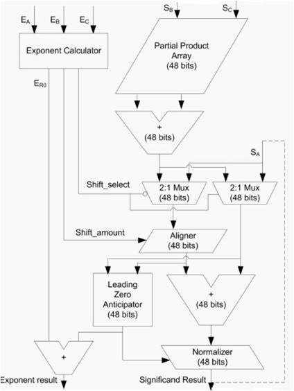
Figure 1. Schematic Diagram of Cascaded FMA
Operation of Cascaded FMA goes through in the following manner: The operation needed to be performed is A+B*C. First two operands are sent into a multiplier for multiplication and the obtained partial products are sent through a carry save adder. Initially for a single precision number, the value accumulated input is assigned to be as 32 bit zero. On the other side, the effective value of the exponent is calculated. The value of shift select and shift amount are calculated from the value of the three exponents.
Shift amount for a single precision number is given by:
SA=27-Difference.
Difference=Ea-(Eb+Ec-127).
Based on shift select, the mantissas are selected and based on shift amount, the mantissas are aligned. After alignment, they are sent to a leading zero anticipator in which the number of leading zeros will be detected and then normalized by normalizer. The final two stages LZA and normalizer include more delay. These are the clock limiting stages. LZA is done in two stages. They are: leading zero anticipation and leading zero detection. First stage anticipates and the second stage calculates the value of number of leading zeros. The normalized result is given back to the accumulated unit and the process continues in the same manner.
Total Latency of the CFMA is equal to multiplier delay and adder delay.
Total Delay=Mul. Delay+N*two input adder delay
Where N is equal to number of input vectors/operands
MFMA is the modified version of Fused Multiply Add (FMA).One difference is the usage of number of operands in MFMA. The operation performed here is A*B+C*D, but in FMA is A*B+C.
Schematic Diagram for a Modified FMA is shown in Figure 2.
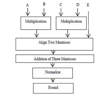
Figure 2. Modified FMA
Operation of MFMA [Nasibeh Nasiri, Oren Segal, Martin Margala "Modified Fused Multiply-Accumulate Chained Unit"] involves five stages. They are:
1. Selection of Exponents
2. Alignment of Mantissas
3. Addition/subtraction of Mantissas
4. Normalization
5. Rounding
In the first stage, the exponents are selected based on the value of the bigger exponent. In order to perform multiplication of mantissas , dadda [A High Speed Binary Floating Point Multiplier Using Dadda Algorithm] multiplication procedure has been used.
Mantissas are multiplied and the maximum of exponents is determined by using comparators and in the second stage mantissas are aligned based on the value of the bigger exponent, i.e., the values of the smaller exponents are subtracted from the value of the bigger exponent. Based on the difference value, the mantissas are aligned. Three mantissas are added and the value is given to a normalizer. The final two steps operate same as that of the previous FMAs, so they are the clock limiting stages for MFMA.
If N is a multiple of 4,then the total latency is given by
Latency=Mul.Delay+(N/2)*Three-input add/sub delay
If N is not a multiple of 4,then latency is given by:
Latency=Mul.Delay+(N/2+1)*Three-input add/sub delay
The major advantage by using pipelining is the re usage of datapath resources. As there is a re-usage of datapath resources, the advantage is hardware usage is greatly reduced, latency remains almost similar for both MFMA [Nasibeh Nasiri, Oren Segal, Martin Margala "Modified Fused Multiply-Accumulate Chained Unit".] with pipelining and without pipelining. The operation performed here is A*B+D*E+F*G+H*I. The operation is almost doubled, but the latency almost remains the same. Figure 3 represents the block diagram of MFMA using Pipelining. First, the operation of MFMA is performed. The block before the PIPO register performs its operation based on pipelining. Here, except the alignment datapath, all the other data paths can be reused, so the hardware usage is almost reduced and is similar to that of MFMA.
Replacing the two input add/sub of FMA [Tomas Lang and Javier D. Bruguera. Floating-point multiply-add fused with reduced latency] with three input add/sub in MFMA with or without pipelining doesn't double the delay, the overall throughput of the floating point vector operations would increase. Because of the pipelined architecture of these fused units, Mul-Delay is the number of stages of the pipeline multiplied by the clock period and the same applies to Three input add_Delay.
The three-input add/sub [Nasibeh Nasiri , Oren Segal , Martin Margala, "Modified Fused Multiply - Accumulate Chained Unit "] allows the designer to reduce latency and assign more burden of computation to the stages 1 to 3 of the floating point datapath with no change in frequency. Although there is extra amount of work in 1 to 3 stages, the delay is reduced in those three blocks, the normalizer and the rounding block still adds more delay Schematic Diagram of MFMA by using Pipelining which is shown in Figure 3.
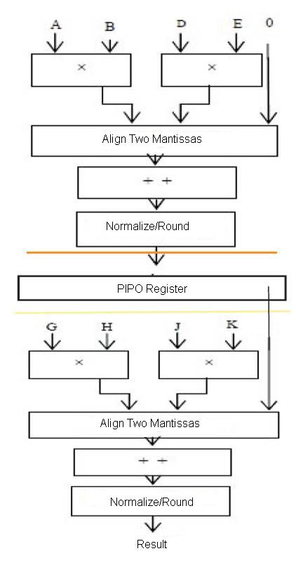
Figure 3. Schematic Diagram Of MFMA
The simulation of this floating point multiplier is performed on Xilinx ISE 10.1.This can be implemented on spartran 3E of FPGA to obtain the same results.
Simulation results of MFMA using pipelining is shown in Figure 4. Delay of MFMA for two A*B+C*D is 59.845 nsec. Power consumption for MFMA is 91mW and is obtained by implementing in Cyclone-II of Quartus tool. Delay of MFMA using pipelining for A*B+D*E+F*G+H*I is 67 nsec. The increase in delay is due to the selection of exponent and mantissa in second stage.
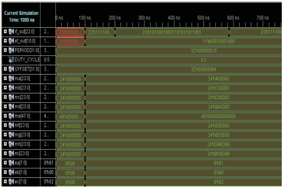
Figure 4.Simulation Results
This paper presents an effective implementation of MFMA using pipelining. By comparing the results, i.e., two stages of MFMA implemented using pipelining has relatively less amount of delay when compared to that of one stage of MFMA , also the number of operands got doubled, the delay has only increased unto 15%, floating point operations generally occupy more area compared to arithmetic operations, but here we can say that by using pipelining for multiple stage will reduce delay, also with the use of pipelining re usage of resources can be done, which will reduce the amount of hardware resources used that reduces the area used for a two staged MFMA. This two stage MFMA can be designed using either of VHDL or Verilog HDL. The authors have used Verilog HDL in order to design/implement the two stage MFMA and MFMA. This is implemented in Xilinx ISE 10.1.