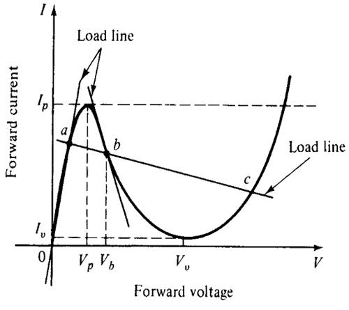
Figure 1. I-V characteristic of a Tunnel Diode with Load Line
It is observed from Figure 1 that the tunnel diode has multiple equilibria as a bi-stable circuit. Due to this characteristics of multiple equilibrium states, it has a nonlinear differential equation, so it becomes necessary to linearize this equation of the tunnel diode circuit for the purpose of steady state analysis of the circuit.
Fuzzy system is applied in various fields of application like an automatic train operation, an automatic container crane operation, elevator control, nuclear reactor control and motor control [6, 7]. In general, it can be classified as Mamdani type and Takagi-Sugeno (T-S) type. The Mamdani type fuzzy control system is well recognized [8], and the T-S type fuzzy system focus basically on the modeling aspect [9].
The model linearization of T-S fuzzy model can be treated as universal approximators as it is able to approximate any non-linear functions with an arbitrary accuracy [10, 11]. A survey on analysis and design for model based fuzzy control system is given in [12]. In [13], a new method is proposed for fuzzy control of non-linear system and many works are also done for fuzzy modeling and control of nonlinear systems [14-17].
In this paper, the T-S fuzzy model for the tunnel diode circuit is developed which has fifth order polynomial equation representing the characteristics of the tunnel diode. The state space equation of the tunnel diode circuit can be obtained by the state-space technique [18] by employing the circuit parameters as state variables.
In the second section, T-S fuzzy model for non-linear system will be introduced. In the third section, the state space and fuzzy model of tunnel diode circuit will be given. In the fourth section, the simulation result is shown and at last discussion will be done from it.
1. T-S Fuzzy Model for Non-linear System
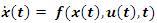
Let us consider a general non-linear system described by the following equation:
The equation (1) can be represented by T-S fuzzy model [9] as given below:
Model rule i
IF
z1 (t) is Nn and ... ... ... ... zp (t) is Nip;
THEN
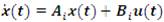
for i=1, 2, 3, ……… r where Nij is the fuzzy set; x(t)∈Rn is the state vector; u(t) ∈Rm is the control input; Ai∈Rn×m , Bi∈Rn×m and z1(t), z2(t) ... ... ... ... zp(t) are the premise variables.
Given a pair of x(t) and u(t), the model dynamics is given as follows:
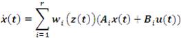
where
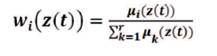
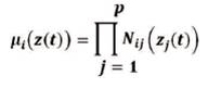
Nij(zj(t)) is the degree of membership function of zj(t) in Nij.
Here, µi(z(t)≥0, for i=1, 2, 3 ... ... ... ... r
and ∑ri=1µi(z(t)> 0 for all t
Therefore, wi(z(t)) ≥ 0
for i=1, 2, 3 ... ... ... ... r and ∑ri=1wi(z(t)=1.
2. T-S Fuzzy Model of Tunnel Diode Circuit
2.1 State Space Model
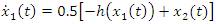
Consider the tunnel diode circuit as shown in Figure 2, which is characterized by iR=h(vR) [18]. Since there are two storing elements L and C in this circuit, therefore two state variables are required. Choosing x1(t)=vC(t) and x2(t)=iL(t) as state variables, and u(t)=E as control input, the state space equation of the tunnel diode circuit is given as [18, 19]:
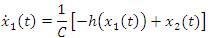
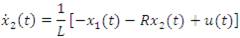
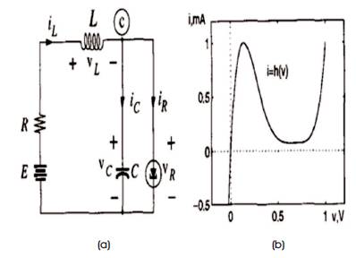
Figure 2 (a) Tunnel Diode Circuit, (b) Tunnel Diode vR -iR Characteristic
Assume the circuit parameter u(t)=1.2 V, R=1.5 KΩ, C=2 pF and L=5 µH. Measuring time in nanosecond and the currents x2(t) and h(x1(t)) in mA [18], the state space model is given by:

Where h(.) is given by
h(x1(t)) = 17.76 x1(t) – 103.79 x1(t)2 + 229.62 x1(t)3 – 226.31 x1(t)4 + 83.72 x1(t) 5
Since (6) and (7) are non-linear differential equations which represent the dynamic of the tunnel diode circuit.
2.2 T-S Fuzzy Model
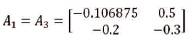
Assume that x1(t)∈(-0.5, 0.5) and using the following fuzzy sets:
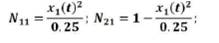
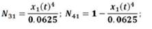
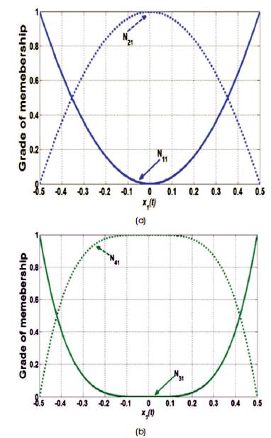
Figure 3. Membership Function of the Fuzzy System
Figure 3 shows the membership function of the given fuzzy sets.
Now, the equations (6) and (7) can exactly be represented by the following fuzzy rules:
Rule 1 IF x (t) is N
THEN  (t)=A1x (t)+B1u(t)
Rule 2 IF x1(t) is N21
THEN (t)=A2x (t)+B2u(t)
Rule 3 IF x1(t) is N31
THEN (t)=A3x (t)+B3u(t)
Rule 4 IF x1(t) is N41
THEN (t)=A4x (t)+B4u(t)
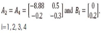
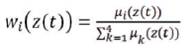
Where
Given a pair of x(t) and u(t), the model dynamics is given as follows:

Where
3. Result
It is observed that the fuzzy system (8) is unstable even though the linear sub-systems are stable. Hence for the steady state analysis of the tunnel diode circuit, it is necessary that the overall fuzzy system must be stable. By employing the Parallel Distributed Compensation (PDC) [20], the fuzzy controller is designed by choosing the feedback gain as:
K1 ,K3 =[169.4955 42.9656]
K2 ,K4 =[169.344 –0.9]
Figures 4 and 5 show the stable response of the tunnel diode circuit.
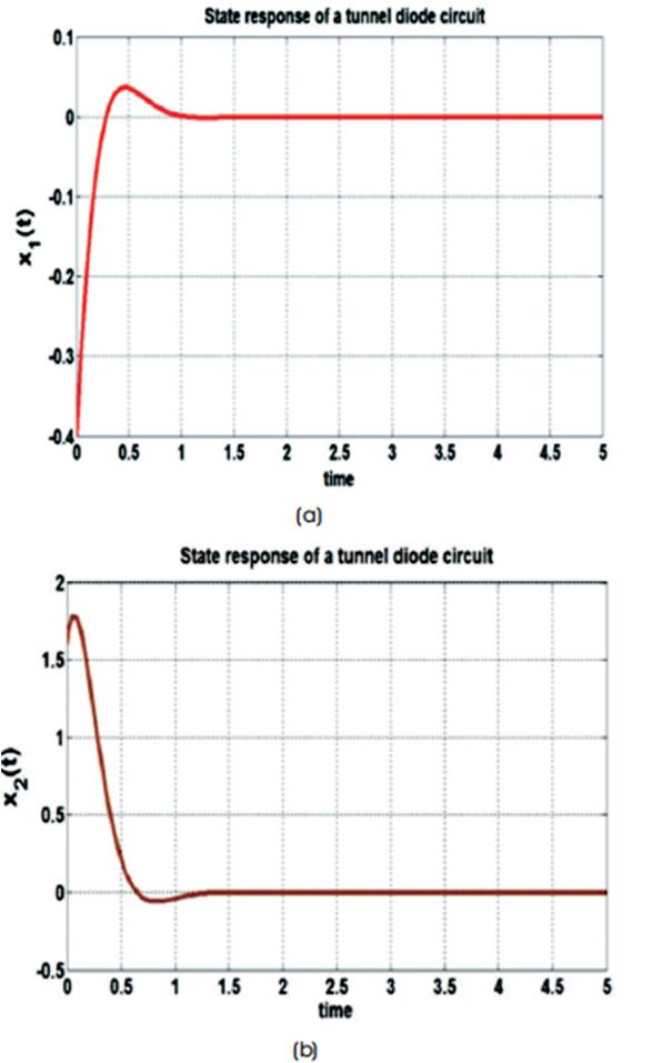
Figure 4. Fuzzy Model response of a Tunnel Diode Circuit with x(0)=[-0.4, 1.6] (a) x1(t), (b) x2(t)
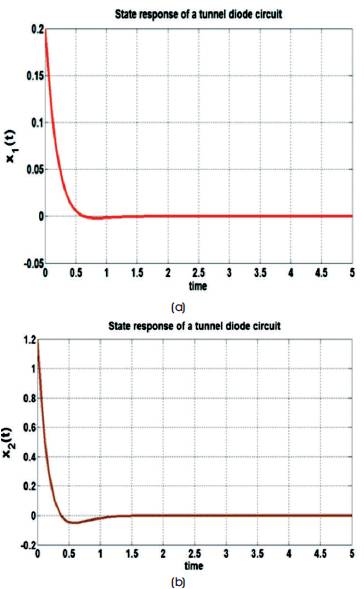
Figure 5. Fuzzy Model response of a Tunnel Diode Circuit with x(0)=[0.2, 1.2] (a) x1(t), (b) x2(t)
Conclusion
In this paper, the fuzzy modelling of tunnel diode circuit is done which is an example of highly nonlinear system. The resulting linearized model is about negative resistance region of the tunnel diode with less approximation error. It is seen from the simulation result that the response of fuzzy system has fast settling time, less overshoot and stable response with high approximation accuracy.