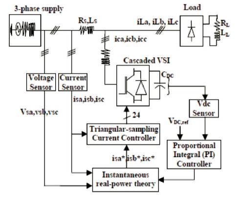
Figure1. Schematic Diagram of DSTATCOM
The “Multilevel Converter” has a massive interest at intervals for the vigour programs enterprise. The fundamental constitution of the construction converter is to decompose a curving voltage from some stages of voltages. Construction voltage offer converters area unit manufacturing as a latest breed of energy converter choice for prime energy applications. These converter topologies will generate high-quality voltage waveforms with vigor semiconductor switches acting at a frequency shut. Among the three construction converter topologies, the five-level and 7-level construction convertors constitute a promising replacement, providing a standard style that will be extended to permit an electrical device-less affiliation. This paper offers a three-segment, five stages and 7 stages cascaded construction voltage supply electrical converter headquartered DSTATCOM for vigour line learning to create stronger vigour satisfactory at intervals of the distribution network. Eventually, a curving PWM (SPWM) procedure is adopted to look at the potency of MLI based DSTATCOM. The outcomes the area unit brought by suggests that of Mat science lab / Simulink application package deal.
In recent years, electrical vigor fine had bought a lot of awareness in vigour engineering. Today power distribution techniques is plagued by extreme vigour pleasant issues. These vigour exceptional problems embrace excessive reactive energy burden, harmonics currents, load unbalance, inordinate neutral current and then forth. The live of energy first-rate depends on the need of the instrumentality that is being well-found. Possibly, the fundamental quantity the vigour fine, refers to conserving a curving waveform of bus voltage at rated voltage and frequency[1]. The waveform of electrical vigour at new unleash stage is solely curving and free from any distortion. Several of the vigour conversion and consumption instrumentality area unit in addition is designed to control at a lower place of pure curving voltage waveforms. Notwithstanding, there are a unit varied instruments that distort the waveform. These distortions could propagate everywhere in the electrical community. The waveform phenomena related to energy may even be characterized into synchronous and non-synchronous phenomena. Synchronous phenomena performs synchronization with the AC waveform at vigour frequency [2], [3]. D-STATCOM may be a bunch of bespoken vigour gadgets for delivering non-toxic distribution power magnificently. They embrace a shunt of voltage that enhances science, utilizing stable state switches for compensating voltage variations.
The DSTATCOM functions are in all probability for sensitiveness, a whole lot that might be staggeringly laid low with fluctuations among the approach voltage. A construction electrical converter will minimize the contrivance voltage and also the output harmonics by growing the amount of output voltage phases. There are three kinds of construction inverters, viz. Cascaded HBridge (CHB), Neutral Purpose Clamped, and Flying Condenser[2- 6]. Among these topologies, CHB inverters are being usually used on the grounds because of their modularity and simplicity. Over a couple of modulation, approaches may additionally be utilized to CHB inverters. CHB inverters can even expand the quantity of output voltage stages merely with the help of skyrocketing the amount of H-bridges. This paper offers a DSTATCOM with a proportional essential controller supported CHB construction (5 degree and 7 degree) electrical converter for the harmonics and reactive energy mitigation of the non-linear, as a whole lot. This form of arrangements had been for the most part used for PQ functions because of development of amount of voltage stages, low shift losses, low magnetic force compatibility for hybrid filters and better order harmonic removing.
Instantaneous real-vigour plan set cascaded structure electrical converter established DSTATCOM is connected at certain intervals in the distribution network from the day, the method of filter produce inductances and operates during a control system. Figure 1 shows the schematic diagram of DSTATCOM methodology which includes a cascaded electrical converter, RL-filters, a compensation controller (instantaneous real-vigour theory), and change signal generator (proposed triangular-sampling current modulator). The three-segment provides connection with the non-linear load and these non-linear currents involve principal and harmonic elements. If the active energy filter presents the whole reactive and the harmonic power, is (t) in all probability be in a part with the utility voltage and will be curving. Presently, the spirited filter must provide the compensation gift so, spirited vigour filter estimates the foremost necessary elements, compensating the harmonic current and reactive vigour.
Figure1. Schematic Diagram of DSTATCOM
The power disturbances arise in all electrical programs, the sensitivity of latest refined electronic devices creates them a lot at risk of the simplest of vigour offer. For a few sensitive devices, a short lived disturbance will principle disorganized data, interrupted communications, a frozen mouse, technique crashes and equipment failure and then forth[2]. A vigour voltage spike will damage the valuable parts. Vigour nice problems cover an enormous varies on disturbances of voltage transients and interruptions[8].
A D-STATCOM (Distribution Static Compensator), is schematically delineated in Figure 1 and it consists of Voltage offer Advocate (VSC), a DC activity accumulator device, a coupling agent related to aboard to the administration arrangement through a coupling device. Necessar y adaptation of the appearance and consequence of the D-STATCOM action voltage is permitted during a position control of alive and acknowledging ability that transfers amid the D-STATCOM and conjointly the AC system. Such agreement permits the accent to blot or accomplish manageable alive and acknowledging ability flows[9-12].
The D-STATCOM frequently activated is primarily for adjustment of voltage, alteration of ability agency and conclusion of accepted harmonics. Such an accent is additionally active to accommodate connected voltage adjustment application associated aboard the controlled device. Throughout this paper, the D-STATCOM is accumulated to adapt the voltage at the aim of accepted affiliation. The control address depends on bowed PWM and wishes the altitude of the RMS voltage at the amount variation.
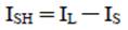
The shunt injected current ISH can be written as,
Where,
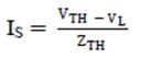
Therefore,
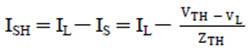
Or,
The complex power injection of the D-STATCOM can be expressed as,
It may be mentioned that the effectiveness of the DSTATCOM in correcting voltage variations depends on the worth of ZTH or fault level of the load bus. Once the shunt injected current, ISH is unbroken in construction with VL , the required voltage correction is achieved while not injecting any active power into the system. On the opposite hand, once the worth of ISH is reduced, a similar voltage correction is achieved with minimum apparent power injection into the system.
The management theme of the shunt active power filter should calculate this reference signals from every part of the electrical converter mistreatment of the fast real-power compensator. As shown in Figure 2, that management theme generates the reference current needed to compensate the load current harmonics and reactive power[9-10]. The PI controller is tried to keep up the DC-bus voltage across the electrical device constant of the cascaded electrical converter. This fast real-power compensator with PI-controller is employed to extract the reference price of current to be remunerated. To boost the performance of distribution system, D-STATCOM was connected to the distribution system [10-12]. D-STATCOM is to be designed as a mistreatment in MATLAB-SIMULINK R2010, a seven 10 version [7].
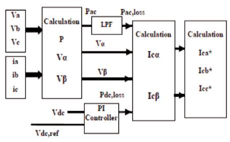
Figure 2. Reference Management Strategy for Fast Real-Power Theory
Total Harmonic Distortion is the summation of all harmonic parts of the voltage or current wave shapes compared against the elemental parts of the voltage or current wave.
DSTATCOM is used for mitigating power quality issues like voltage variations with load reconciliation in 3-phase 4-wire distribution network. Four leg electrical converters are employed for the compensation purpose and the synchronous organization theory primarily based on manage mentler is employed with the control of DSTATCOM.
Here the simulation is applied by 5 cases.
1. Non-linear load not with DSTATCOM and APF.
2. Non-linear load with APF.
3. Non-linear loads with DTSATCOM and APF.
4. Non-linear load with DSTATCOM, PI Controller and five level cascaded construction.
5. Non-linear load with DSTATCOM, PI Controller and seven-level cascaded construction.
Figure 3 shows the simulink model for three phase distribution system containing non-linear load without compensation (DSTATCOM). Figure 4 shows the waveforms for Grid, Load and filter current variation of the three phase system with respect to time without DSTATCOM. Figure 5 shows the power loss before and after filter without DSTATCOM.
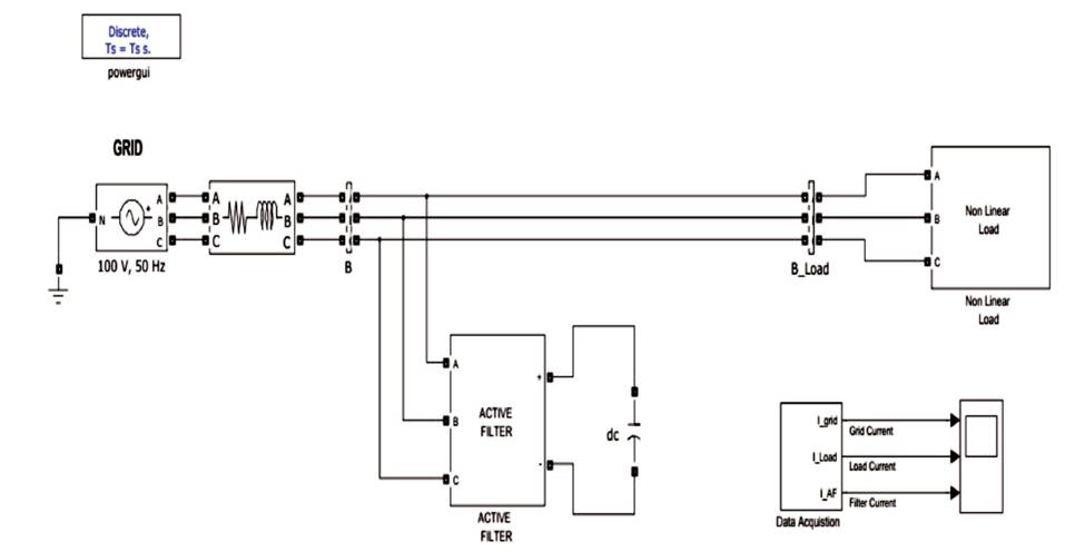
Figure 3. Non-linear Load without DSTATCOM
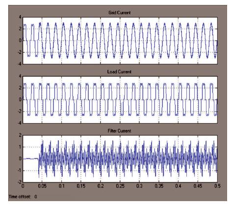
Figure 4. Grid, Load and Filter Current Variation w.r.t Time without DSTATCOM
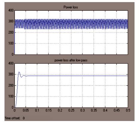
Figure 5. Power Loss Before and After Filter
Figure 6 shows that the THD Value is 26.25% of the three phase system without compensation. Figure 7 shows the three phase system containing non-linear load with compensation (DSTATCOM). Figure 8 shows voltage sag variation with non-linear load and DSTATCOM and Figure 9 gives THD value as 26.11% for the system that contains nonlinear load with compensation (DSTATCOM).
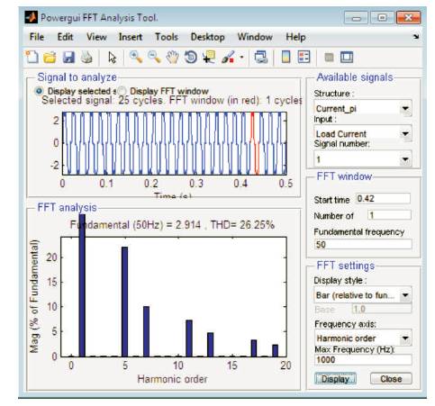
Figure 6. THD is 26.25%
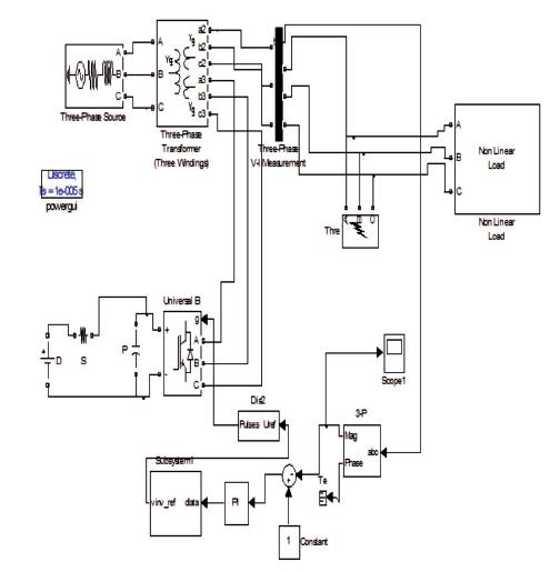
Figure 7. Non-linear Load with DSTATCOM
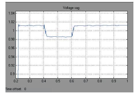
Figure 8. Voltage Sag Variation with Non-Linear Load and DSTATCOM
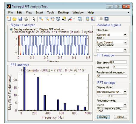
Figure 9. THD is 26.11%
Table 1 describes the comparison of non-linear load with and without DSTATCOM for different power quality problems like THD values, power loss, voltage sag variation, etc,. Figure 10 shows the simulink model for the three phase system contain non-linear loads with compensation of 5- level MLI-DSTATCOM and neutral current compensation by using T-connected transformer. Figure 11 shows the subsystem of Five- Level Diode Clamped Inverter with TConnected Transformer Connection. Figure 12 gives the line voltages versus time variation for the three phase system compensated with 5-level MLI-DSTATCOM and neutral currents compensation with T-connected transformer. Figure 13 gives the information about THD variation with respect to time for three phase system compensated with 5 -level MLI-DSTATCOM and neutral currents compensation with T-connected transformer. Figure 14 shows the zoomed view of THD variation with respect to time for the three phase system compensated with 5-level MLI-DSTATCOM and neutral currents compensation with T-connected transformer.
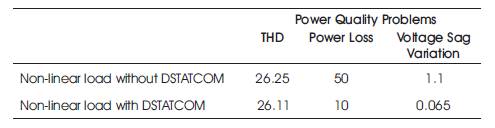
Table 1. Comparison of Non-linear Load with and without DSTATCOM for Different Power Quality Problems
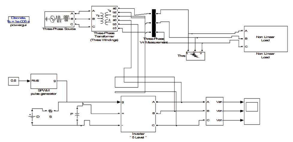
Figure 10. Non-linear Load with DSTATCOM, Five-Level Diode Clamped Inverter with T-Connected Transformer Connection
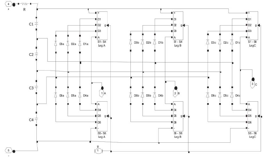
Figure 11. Subsystem of Five-Level Diode Clamped Inverter with T-Connected Transformer Connection
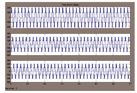
Figure 12. Line Voltages Versus Time Variation
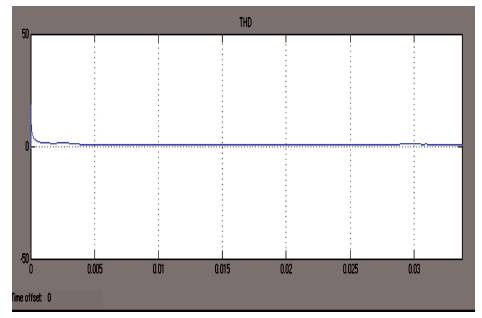
Figure 13. THD Variation w.r.t Time
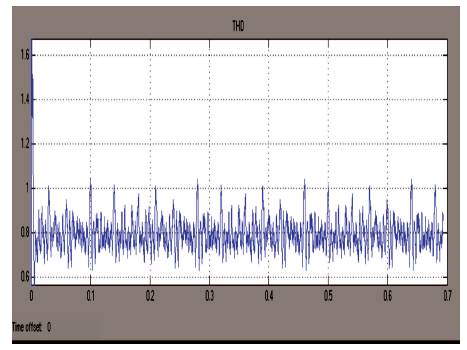
Figure 14. Zoomed View of THD Variation w.r.t Time
Figure 15 shows the simulink model for the three phase system containing non-linear load with DSTATCOM, Five- Level Diode Clamped Inverter with Star-delta Connected Transformer Connection.
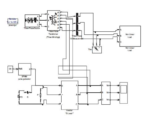
Figure 15. Non-Linear Load with DSTATCOM, Five-Level Diode Clamped Inverter with Star-delta Connected Transformer Connection
Figure 16 gives the information about line voltages versus time variation for three phase system containing non-linear loads with DSTATCOM, and a Five-Level Diode Clamped Inverter with Star-delta Connected Transformer Connection. Figure 17 shows the simulink model of three phase system with nonlinear Load with DSTATCOM, and a Five-Level Diode Clamped Inverter with Zig-Zag Connected Transformer Connection. Figure 18 gives the information about line voltages variation with respect to time for the three phase system containing nonlinear load with DSTATCOM, and a Five-Level Diode Clamped Inverter with Zig-Zag Connected Transformer Connection. Figure 19 shows THD variations of three phase system containing the non-linear loads with DSTATCOM, and Five-Level Diode Clamped Inverter with Zig-Zag Connected Transformer Connection.
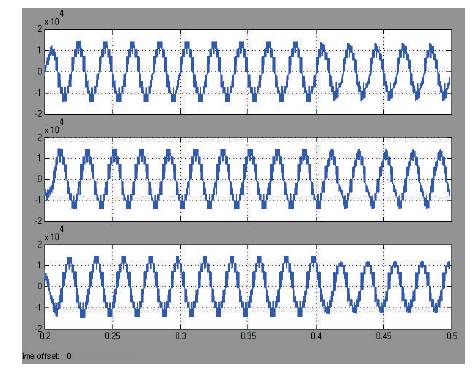
Figure 16. Line Voltages Versus Time Variation
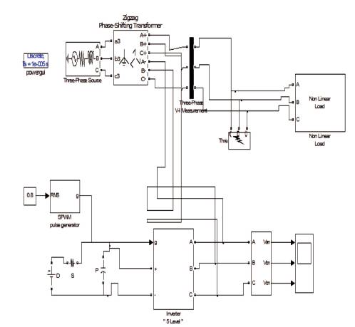
Figure 17. Non-Linear Load with DSTATCOM, Five-Level Diode Clamped Inverter with Zig-Zag Connected Transformer Connection
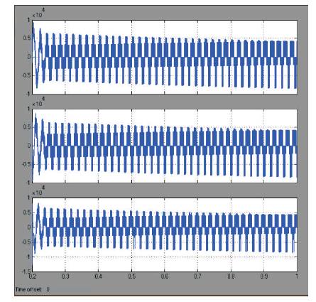
Figure 18. Line Voltages Variation with respect to Time
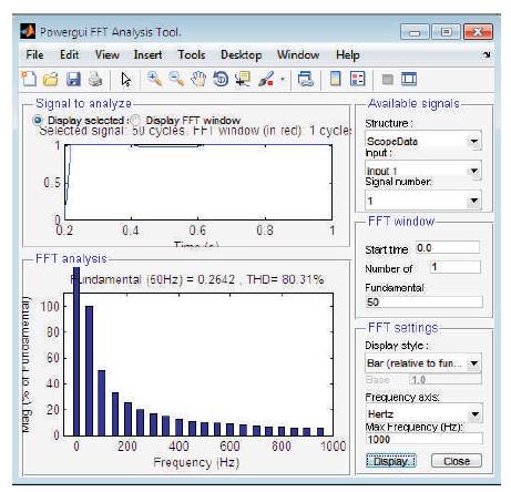
Figure 19. THD Variation is 80.31%
Figure 20 shows the simulink model of the three phase system containing non-linear loads with DSTATCOM, and a Seven-Level Diode Clamped Inverter with 'T' Transformer Connection. Figure 21 gives voltages levels of seven-level diode-clamped multilevel inverter. Figure 22 shows simulink model of three phase system containing non-linear load with DSTATCOM, and Seven-Level Diode Clamped Inverter with Star-Delta Transformer Connection. Figure 23 gives the THD values for the three phase system containing nonlinear load with DSTATCOM, and Seven-Level Diode Clamped Inverter with Star-Delta Transformer Connection.
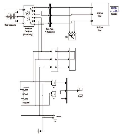
Figure 20. Non-Linear Load with DSTATCOM, Seven-Level Diode Clamped Inverter with 'T' Transformer Connection
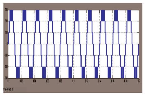
Figure 21. Voltage of Seven-Level Diode-Clamped Inverter
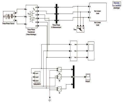
Figure 22. Non-Linear Load with DSTATCOM, Seven-Level Diode Clamped Inverter with Star-Delta Transformer Connection
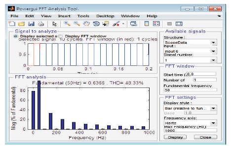
Figure 23. THD is 48.33%
Figure 24 shows the simulink model for three phase system containing non-linear load with DSTATCOM, and Seven- Level Diode Clamped Inverter with Zig-Zag Transformer Connection. Figure 25 gives the values of THD for three phase system containing non-linear load with DSTATCOM, and Seven-Level Diode Clamped Inverter with Zig-Zag Transformer Connection.
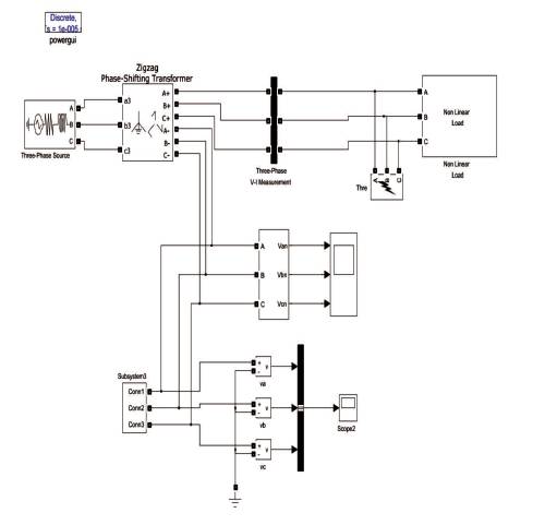
Figure 24. Non-Linear Load with DSTATCOM, Seven-Level Diode Clamped Inverter with Zig-Zag Transformer Connection
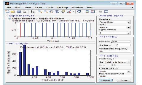
Figure 25. THD is 55.63%
Table 2 gives a brief comparison of THD values for non- linear load of five and seven-level diode-clamped inverter for different transformer connections.
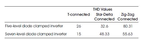
Table 2. Comparison of THD Values for Non-linear Load of Five and Seven-Level Diode-Clamped Inverter for Different Transformer Connections
Figure 26 shows the simulink model for three phase system containing non-linear load with DSTATCOM, and Five-Level Flying Capacitor Inverter with 'T' Transformer Connection.
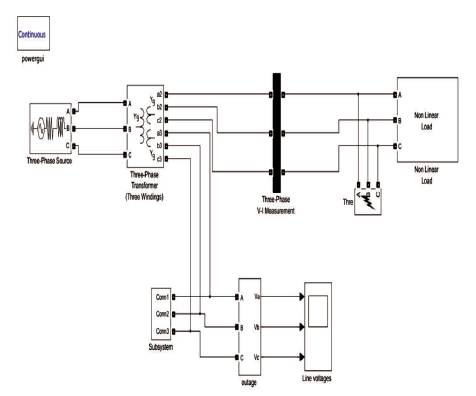
Figure 26. Non-Linear Load with DSTATCOM, Five-Level Flying Capacitor Inverter with 'T' Transformer Connection
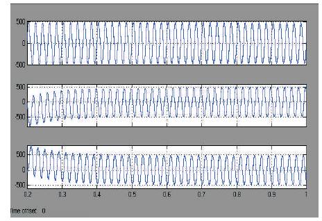
Figure 27. Line Voltages Variation w.r.t Time
Figure 27 shows line voltages variation with respect to time for non-linear load with DSTATCOM, and Five-Level Diode Flying Capacitor Inverter with 'T' Transformer Connection.
Figure 28 shows THD values for non-linear load with DSTATCOM, and Five-Level Flying Capacitor Inverter with 'T' Transformer Connection. Figure 29 shows the simulink model for three phase system containing non-linear load with DSTATCOM, and Five-Level Flying Capacitor Inverter with Star-Delta Transformer Connection. Figure 30 gives the values of THD for three phase system containing non-linear load with DSTATCOM, and Five-Level Flying Capacitor Inverter with Star-Delta Transformer Connection.

Figure 28. THD is 31.52%
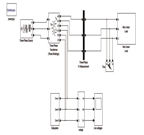
Figure 29. Non-Linear Load with DSTATCOM, Five-Level Flying Capacitor Inverter with Star-Delta Transformer Connection
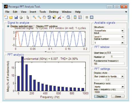
Figure 30. THD is 24.90%
Figure 31 shows the simulink model for three phase system containing non-linear load with DSTATCOM, and Five-Level Diode Flying Capacitor Inverter with Zig-Zag Transformer Connection. Figure 32 describes Line voltage Variations with respect to time of the non-linear load with DSTATCOM, and Five-Level Diode Flying Capacitor Inverter with Zig-Zag Transformer Connection. Figure 33 shows THD vales for nonlinear load with DSTATCOM, and Five-Level Diode Flying Capacitor Inverter with Zig-Zag Transformer Connection.
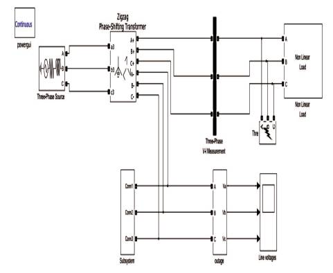
Figure 31. Non-Linear Load with DSTATCOM, Five-Level Diode Flying Capacitor Inverter with Zig-Zag Transformer Connection
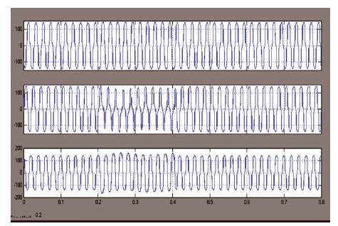
Figure 32. Line Voltages Variation w.r.t Time
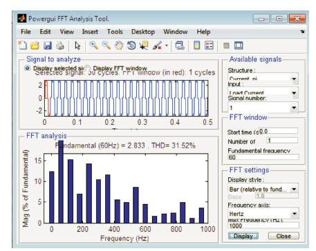
Figure 33. THD is 31.52%
Table 3 describes the comparison of THD values for nonlinear load of five and seven-level Flying Capacitor Inverter for different transformer connections. Figure 34 shows the simulink model for three phase system containing nonlinear load with DSTATCOM, and Five-Level Hybrid Cascaded H-Bridge Inverter with 'T' Transformer Connection. Figure 35 shows the simulink subsystem of non-linear load with DSTATCOM, and Five-Level Hybrid cascaded H-Bridge Inverter with 'T' Transformer Connection. Figure 36 gives the THD vales for non-linear load with DSTATCOM, and Five-Level Hybrid Cascaded H-Bridge Inverter with 'T' Transformer Connection. Figure 37 shows the simulink model for the three phase system containing nonlinear loads with DSTATCOM, and Five-Level Hybrid Cascaded H-Bridge Inverter with Star-Delta Transformer Connection. Figure 38 gives the THD values for non-linear load with DSTATCOM, and Five-Level Hybrid Cascaded HBridge Inverter with star-delta Transformer Connection. Figure 39 shows the simulink model for three phase system containing non-linear load with DSTATCOM, and Five-Level Hybrid Cascaded H-Bridge Inverter with Zig-Zag Transformer Connection. Figure 40 shows the line voltages variation with respect to three phase system containing non-linear load with DSTATCOM, and Five-Level Hybrid Cascaded H-Bridge Inverter with Zig-Zag Transformer Connection. Figure 41 gives the values of THD for three phase system containing non-linear load with DSTATCOM, and Five-Level Hybrid Cascaded H-Bridge Inverter with Zig-Zag Transformer Connection.
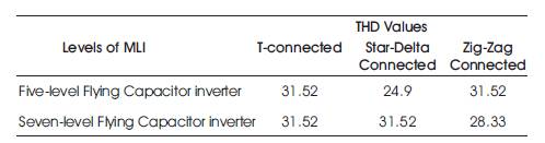
Table 3. Comparison of Non-linear Load of Five and Seven-Level Flying Capacitor Inverter for different Transformer Connections
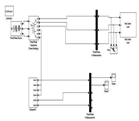
Figure 34. Non-Linear Load with DSTATCOM, Five-Level Hybrid Cascaded H-Bridge Inverter with 'T' Transformer Connection
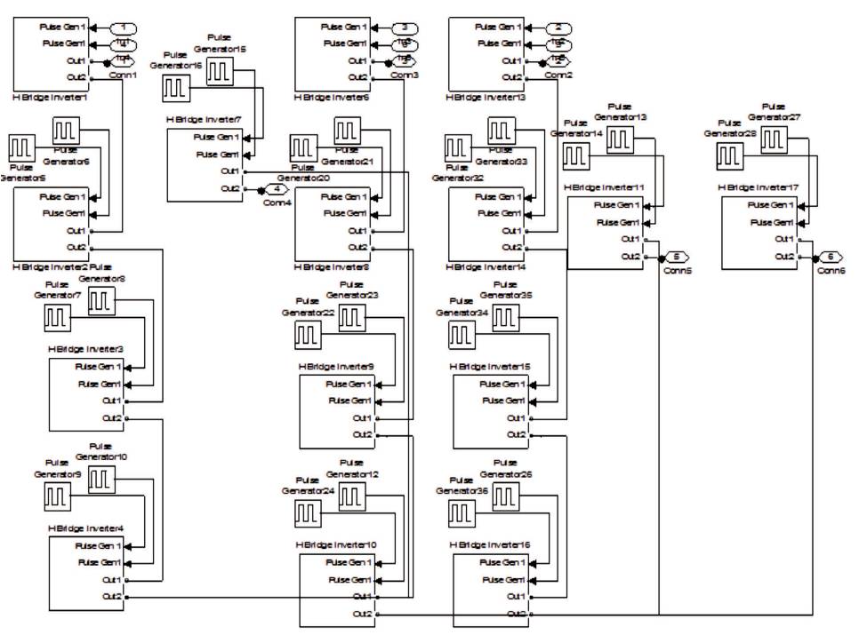
Figure 35. Subsystem of Non-Linear Load with DSTATCOM, Five-Level Hybrid Cascaded H-Bridge Inverter with 'T' Transformer Connection
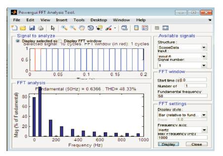
Figure 36. THD is 48.33%
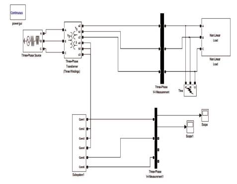
Figure 37. Non-Linear Load with DSTATCOM, Five-Level Hybrid Cascaded H-Bridge Inverter with Star-Delta Transformer Connection
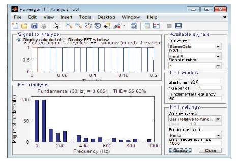
Figure 38. THD is 55.63%
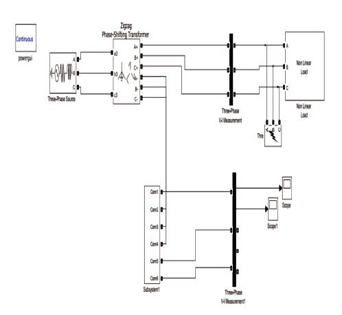
Figure 39. Non-Linear Load with DSTATCOM, Five-Level Hybrid Cascaded H-Bridge Inverter with Zig-Zag Transformer Connection
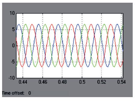
Figure 40. Line Voltages Variation w.r.t Three Phase System
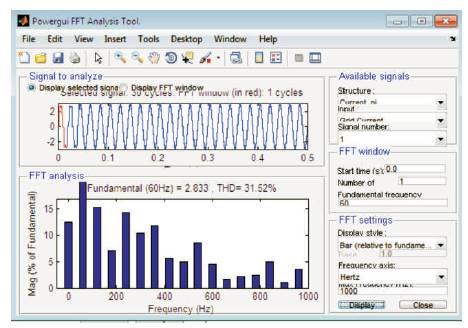
Figure 41. THD is 31.52%
Table 4 describes the comparison of THD values for nonlinear load of five and seven-level Hybrid Cascaded HBridge Inverter for different Transformer connections. Table 5 describes the comparison of various parameters between 5-levels and 7-levels of MLI-DSTATCOM with different Transformer connections. Table 6 describes the system specification for 5-level and 7-level MLI-DSTATCOM with different Transformer connection.
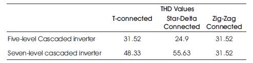
Table 4. Comparison of Non-linear Load of Five and Seven-Level Hybrid Cascaded H-Bridge Inverter for Different Transformer Connections
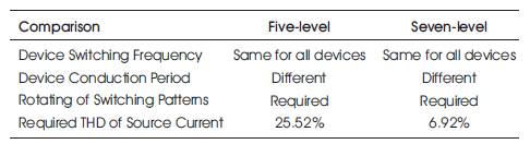
Table 5. Comparison between Two Types of MLI's
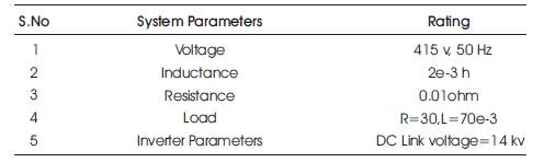
Table 6. System Specifications
In Engineering applications, this is often called reliableness analysis, and also the times might represent the time to failure of a chunk of apparatus.
To use MATLAB (R) and also the Statistics Toolbox (TM) to research period knowledge. Examine the distribution of the information, considering alternative ways of starting at a chance distribution. A chance density perform indicates the relative chance. The Weibull may be a common distribution for modeling period knowledge.
The Weibull distribution may be a generalization of the exponential distribution. If lifetime follows the Associate in Nursing exponential distribution, they would need a continuous hazard rate. This suggests that they are doing not age, within the sense that the chance of observant is a failure in Associate in Nursing interval, given survival to the beginning of that interval, does not depend upon wherever the interval starts[13]. A Weibull distribution encompasses a hazard rate that will increase or decrease.
One such way would be to use a unique constant quantity distribution. The Statistics chest includes functions for different common period distributions comparable to the lognormal, gamma, and Birnbaum-Saunders, furthermore as several different distributions that don't seem to be normally employed in the period models[14].
Other ways would be to use a mix of 2 constant quantity distributions-one representing early failure and the other representing the remainder of the distribution.
Figure 42 describes the reliability analysis for three phase system containing non-linear load compensation with MLIDSTATCOM with different transformer connections.
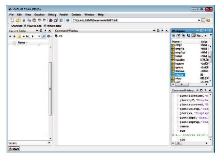
Figure 42. Data Variables in Workspace
Figure 43 gives the information about Hazard rate for nonparametric model for the three phase system containing non-linear load compensation with MLI-DSTATCOM with different transformer connections.
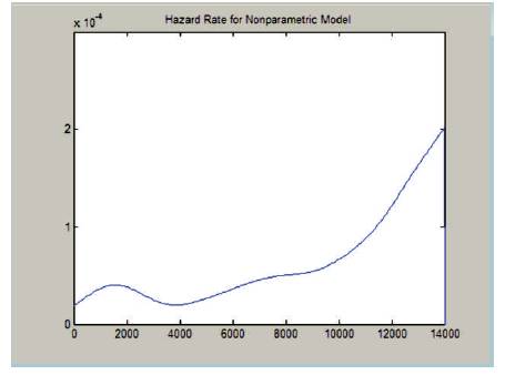
Figure 43. Hazard Rate for Non-parametric Model
A seven level cascaded structure voltage supply electrical converter based DSTATCOM exploitation fast real power controller is found to be a good answer for cable acquisition. DSTATCOM with the projected controller reduces harmonics and provides reactive power compensation because of non-linear load currents. As a result, supply current(s) become curving and unity power issue is additionally achieved below each transient and steady state conditions. The projected fast real-power controller uses reduced computation for reference current calculations compared to standard approach. The cascaded electrical converter switch signals square measure generated exploitation triangular-sampling current controller. It provides a dynamic performance below transient and steady state conditions. As evident from the simulation studies, DC bus capacitance voltage settles early and has tokenized ripple thanks to the presence of PI-controller. Simulation results below nonlinear masses square measure is investigated and located that the seven level electrical converter results square measure is higher than 5 level electrical converter. Responsibility analysis is finished by estimating the hazard rate distribution.