Figure 1. Schematic Diagram of DFIG WT System
Wind energy is a substantial source of renewable energy which has a potentiality of generating energy on a large scale. Developing this new technology becomes more demanding as variable speed wind turbine is highly efficient than the fixed one. DFIG is widely used in variable speed constant frequency wind energy generation system. These type of machines are controlled with the power converters connected to the rotor, where the controlled power is only a portion, approximately equal to the slip of the stator power. DFIG consists of an asynchronous machine, in which the stator is directly connected to the grid and the rotor is connected to the grid via two power electronic converters (back-to-back converter). This characteristic of DFIG has increased the wind energy penetration, but it is more prone to the electrical grid disturbances. This paper provides a review for the protection and control strategy to enhance the LVRT ability of a wind turbine driven DFIG. In this paper, three LVRT methods for protection of DFIG during low voltage events are explained. The three methods are crowbar, DC chopper, series dynamic resistances, and also two hybrid methods named DC chopper with crowbar and DC chopper with series dynamic resistance respectively.
As a result of the economical and environmental advantages, Wind Energy Conversion Systems (WECS) have gigantic growth in the past decade. The elevated interest in wind energy has made it necessary to model and experimentally evaluate an entire wind energy conversion system, so as to attain a better understanding and to access the performance of various systems. Wind energy has been acclaimed as the fastest growing renewable power generation technology in the world, with its annual growth rate in excess of 30% and foreseeable penetration of 12% of global electricity demand by 2020 [1]. The DFIG is the most widely used device for wind power generation. DFIG is a popular wind turbine system because of its advantages like, it can operate in generator as well as motor mode for both sub and super synchronous speed mode, also we can obtain speed variation of 30% around synchronous speed, and the size of converter is related to the selected speed range [2]. Due to the advantageous characteristics, mostly the grid connected wind turbines operate at a variable speed, presently the wind market is dominated by Doubly Fed Induction Generator (DFIG) with the multiple stage gearbox [3-4]. The ability of the wind turbine to stay connected to the grid during voltage dips is called as the Low-Voltage Ride-Through (LVRT) capability. In order to fulfill LVRT conditions for DFIG based wind turbine, there are two important conditions to be considered during a fault condition. The first one is the over current that can occur in the rotor and stator circuits, while the second one is over voltage in the DC link, both directs towards the unbalanced energy that can't be transmitted into the grid. For reducing the influx currents in the rotor, and the DC link over voltage during the faults, an advanced control strategy for the rotor and grid size converters are used [5- 12]. Among the available control strategies, the crowbar protection is mostly used. On the occurrence of faults, the rotor side converter will be blocked, and the crowbar circuit which is installed across the rotor terminals, will be triggered to damp over current in the rotor circuit. Therefore, the generator operates as a conventional induction machine, which absorbs a reactive power from the faulted grid. The chopper circuit, with a resistor across the DC bus, is usually used along with the crowbar to smooth the DC link voltage by dissipating the excessive power over the DC bus.
To provide a good fault ride through capability for a DFIG based wind turbine, the DFIG wind turbine and all its associated power converters should have the capability to protect itself without disconnecting it during the fault in the power grid. When the wind turbine is subjected to various types of symmetrical and unsymmetrical fault, voltage dips and over current phenomena occur in the rotor winding, and this leads to an unbalanced condition of the DFIG wind turbine. The objective of this paper is to take an overview of different control strategy. Here five methods of LVRT protection has been studied. The five methods are crowbar, DC chopper, series dynamic resistances and two hybrid methods that combine DC chopper with crowbar, and DC chopper with a series dynamic resistances respectively. The devices operate only when there are some abnormal fault conditions that occur in the system, otherwise the device remains off in normal conditions.
DFIG has a very appealing characteristic as a wind generator, because the power processed by the power converter is only a fraction of total power rating of the DFIG, that is typically 20-30%, and therefore its size, cost and losses are much smaller compared to a full size power converter [13] used in variable speed wind generators. DFIG is basically a wound rotor induction machine with a multiphase wound rotor with multiphase slip rings assembly and brushes enabling access to the rotor. The windings of rotor are connected to the grid through an AC-DC-AC converter. DFIG can operate at a broad range of speed depending on the wind speed or other specific operation requirements. Thus, it allows a better capture of wind energy. There are basically two machine types that are generally used in the wind turbine application, that are Permanent Magnet Synchronous Generator (PMSG) and Doubly Fed Induction Generator (DFIG). The power generated by the PMSG based system is processed through the converters, and so during the faults, PMSG can be fully controlled. On the other hand, only up to 30% of the whole power passes through the converters in DFIG system. Thus, controlling the entire power during and after the fault condition with DFIG is more difficult than with PMSG and requires a careful study. Active and reactive power of the stator and rotor side are controlled with Rotor Side Converter (RSC), and Grid Side Converter (GSC), respectively.
A DFIG has the main advantage, that power can be imported from or exported to the grid through power electronics converter. This permits the system to support the grid during severe voltage disturbances, therefore improving the system stability. By controlling the rotor currents and voltages, the synchronization of the machine with the grid is maintained even when the wind speed varies. Under very light load conditions, the wind energy is utilized more efficiently than a fixed speed wind turbine. Only up to 30% of the power is fed to the grid through the converter, while the remaining is fed directly to the grid. As a result, the cost of the converter is low and efficiency of DFIG is also good [14].
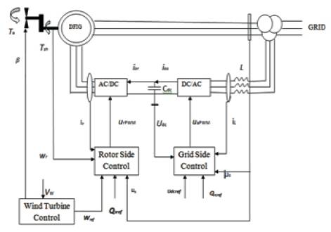
The schematic diagram of a grid connected DFIG Wind Turbine system is shown in Figure 1. The DFIG Wind Turbine system which includes the wind turbine, the drive train, the induction generator, the back-to-back PWM converters, and the control system, is connected to the grid through a transformer. The control system consists of two control levels, including the Wind Turbine control and the DFIG control. The WT level controls the output mechanical power of the wind turbine through the pitch angle, and generates the reference value for the rotor speed of DFIG based on measured wind speed and optimum power speed characteristic curve. A two stage control strategy is used to implement the power optimization strategy below the rated wind speed [15], and the power limitation strategy above the rated wind speed. The DFIG control level which includes the rotor and grid side controllers is to control the active and reactive power of the DFIG using the vector control technique.
Figure 1. Schematic Diagram of DFIG WT System
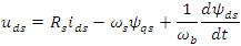
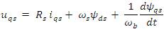
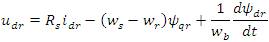
The voltage equations of the stator and rotor circuits of the induction generator can be given in a d-q reference frame rotating at the synchronous speed [16], [17].
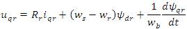
where  and
and 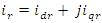 are known as the stator and rotor current vectors, respectively,
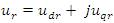 are the stator and rotor voltage vectors, respectively,
 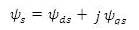 and
and
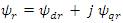 are the stator and rotor flux vectors respectively, ωb, ωs, and ωr are the base, stator and rotor angular frequencies, respectively. The system model is drafted in the per unit system with the time t in seconds.
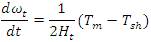
When considering the dynamic stability of the DFIG Wind Turbine, the two-mass model of the drive train is important because the wind turbine shaft is relatively softer than the typical steam turbine shaft in conventional power plants [18]. Equations which represent the two-mass model of the drive train are expressed as,
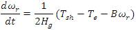
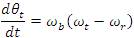
where ωt is the wind turbine speed.
Hg and Ht [SI unit (s)] are defined as the generator and turbine inertia constants, respectively.
B is the friction coefficient of the generator.
θt is the shaft twist angle, which is radian (rad).
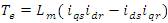
The electromagnetic torque, Te is the shaft torque Tsh, and Tm is the mechanical torque which is the torque input of the wind turbine, are

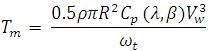
where ρ is defined as the air density,
R is defined as the turbine radius,
β is defined as the pitch angle,
Vw is defined as the wind speed,
Cp is defined as the power coefficient, and
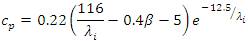
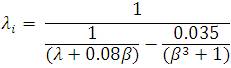
where  is defined as the blade tip speed ratio,
 has a maximum value
  for the optimal tip speed ratio
  and
and  is the optimized pitch angle .
The pitch angle of the blade is controlled to enhance the power extraction of the WT and also to prevent overrated power production in high wind. The pitch servo is modelled as,
When the power grid is subjected to the unbalanced conditions like short-circuit fault, the bus voltage at the PCC drops, and therefore introducing unwanted transients in the stator and rotor currents. The low voltage also prohibit the full transmission of the generated active power from the Wind Turbine, leading to the significantly increased fluctuations of the currents and voltages in the DFIG system. To protect the power electronics devices that are sensitive to over-currents and over-voltages, the main purpose of introducing the LVRT strategy is to ensure the DFIG can stay connected to the faulted grid by effectively limiting the stator and rotor currents as well as the DC-link voltage.
The main power is processed through the stator of the DFIG without any power electronic interface. The control of power is carried out through relatively smaller size back-to-back converter placed in between the stator and rotor windings. The rotor supply circuit comprises a grid side inverter and a rotor side inverter that is linked through a DC bus. The DC bus capacitor decouples the two inverters, allowing them to be independently controlled.
The task of the grid side inverter is to regulate the voltage of the DC bus, Vdc . To achieve this, a voltage can be controlled by the d-axis component of the line current that affects the real power exported or imported from the grid. The grid side converter can also be used for system power factor control by adding a reactive power loop to control the q-axis currents.
The purpose of the rotor inverter is to control the generator speed to achieve maximum power from the wind over a range of wind velocities. The rotor side converter control scheme is based on a multitiered structure that comprises a speed, power and current control loop. It should be noted that, omission of the power control loop is possibly by implementing the decoupled current control. Speed control is implemented by controlling the active power reference to the power control loop, the reactive power reference is set to zero, because it is assumed that grid side converter will supply the needed reactive power to the system. The current controller tracks the power reference by controlling the rotor currents. Current control is performed in a d-q reference frame that is rotating with the stator flux [19].
The crowbar protection circuit is composed of three phase diode bridge and bypass resistors [20-22]. The passive crowbar connects the crowbar resistance bypassing the RSC until the interruption of DFIG. The active crowbar control scheme connects the crowbar resistance when necessary, and disables it to resume DFIG control without interruption of DFIG. The crowbar circuit used here consists of three phase rectifier, power resistor and a series of IGBT switch and the turn off ability of the IGBT is necessary for an active crowbar as shown in Figure 2.

Figure 2. Crowbar Protection Circuit
When the value of the terminal voltage decreases below the threshold value of comparator, the crowbar will be switched on, and the RSC will be switched off by stopping IGBTs operation. When the terminal voltage exceeds the threshold value, the crowbar will be switched off, and the RSC will be switched on.
The DC chopper consists of a power resistor which is connected in parallel with the DC capacitor through an IGBT power switch in order to turn off the DC chopper, when the DC voltage is within the range. It is connected in parallel with the DC link capacitor to protect it from over voltage during low grid voltage [23]. This protects the DC link capacitor and IGBTs from over voltages resulted from various grid faults [24]. The DC chopper circuit is shown in Figure 3.
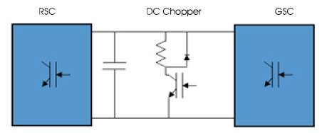
Figure 3. DC Chopper Circuit
When the value of the DC-link voltage exceeds the threshold value of the comparator, the chopper will be switched on, but the RSC is still connected to the rotor of the DFIG, and when the DC voltage decreases under threshold value, the DC chopper will turn off.
In this technique, the series dynamic resistor is connected in series with the rotor, and this connection can limit the over currents during the fault events. The layout of the SDR protection circuit is shown in Figure 4. SDR is controlled by a power-electronics switch, in normal operation, where the switch is on and the resistor is bypassed. During fault conditions, the switch is OFF and the resistor is connected in series with the rotor windings. The main differences among the SDR, the crowbar and the DC-link chopper is its connection topology. The crowbar and the Dc chopper are both shunt connected devices and control the voltage, while the SDR has the distinct advantage of controlling the current magnitude directly. Moreover, with the SDR, the high voltage will be shared by the series resistance. Therefore, the induced over voltage may not lead to loss of power converter control. SDR can limit the rotor over voltage as well as, limit the high rotor current during the faults. The rotor current limiting, can reduce the charging current to the DC-link capacitor, and hence avoid DC-link over voltage.
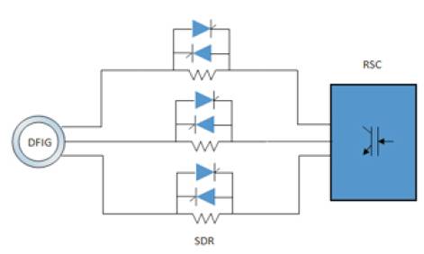
Figure 4. SDR Protection Circuit
When the value of the generator terminal voltage decreases under the threshold value of the comparator, the SDR will be switched on, but the RSC is still connected to the rotor of the DFIG and when the terminal voltage exceeds the threshold value, the SDR will be switched off.
LVRT has become one of the biggest challenge facing wind turbines from massive deployment, in particular those using DFIGs. This type of generator is adversely sensitive to grid disturbance, in particular voltage sags. High penetration of WT's imposes a big challenge to the safe operation of the power system. To ensure the security of an electric supply with substantial wind power, the WT must ride through during voltage dip caused due to different grid faults. The effect of three phase short circuit fault on grid voltage is most severe. While connecting a local load in between DFIG and the grid LVRT requirement should be confirmed which otherwise may lead to LVRT failure during a fault. To overcome this sensitivity, several control strategies has been proposed. These strategies have been examined and advantages of each one have been discussed. Future research should be focused on the development of DFIG robust nonlinear control strategies.
In this paper, all the LVRT control strategy has been studied. Crowbar and SDR are the resistances connected in parallel and series of the rotor side respectively. They only dissipate the excess energy across the resistances, whenever the system faces some abnormal fault conditions. They do not utilize the excess energy. One way to utilize the energy is to connect the crowbar and the DC chopper in such a manner that, whenever the system encounter some abnormal conditions, all the excess energy would go to feed the rotor, which normally takes power from the grid side. Hence in this way, these excess energies can be utilized.