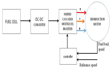
Figure 1. Fuel Cell Fed Hybrid Multilevel Inverter
This paper proposes a hybrid cascaded multilevel inverter to get a desired ac voltage from several dc voltages. These multilevel inverters are used for high power applications. These inverters give less total harmonic distortion (THD), and also can reduce the power switches when compared with conventional cascaded multilevel inverters. In general, the output of an inverter is controlled with the help of various controlling techniques. In this proposed work, these multi level inverters are controlled with modified SPWM scheme to reduce the switching losses. The objective of this paper is to evaluate the performance of an induction motor with the proposed model of fuel cell powered hybrid cascaded multilevel inverter and to control the speed of the induction motor. MATLAB/SIMULINK platform is chosen to simulate the proposed model and control technique.
Multilevel Inverters are extensively used in a variety of industrial applications such as in ac drive system, Va r compensators and power supplies and to handle high power ratings [1]-[2]. Some sort of connections (seriesseries, series-parallel, parallel-parallel, parallel-series) are necessary to overcome the troubles of the narrow voltage and current ratings of power electronic devices. Multilevel inverters have the ability to synthesize waveforms with a better harmonic spectrum, and therefore suitable to attain higher voltages. They are applied in many industrial applications such as, AC power supplies, static VAr compensators and drive systems etc. Different converters Topologies have been proposed [3] for nonconventional energy sources to control power flow effectively in both grid-connected as well as in stand-alone applications. Generally, three different major multilevel converter structures have been reported in the literature: cascaded H-bridge converters with separate dc sources (SDCS), diode clamped (neutral clamped), flying capacitor (capacitor clamped).
In this paper, cascaded H-bridges converter is used with separate dc sources (Photovoltaic and Fuel cell) for getting higher output voltages. However, this topology contains huge number of switches and this number will be depended upon output voltage levels. Numerous modulation and control strategies are developed in order to eliminate the selective harmonics such as Pulse width modulation (PWM), Sinusoidal PWM, Space Vector PWM, Selective harmonic elimination. In this paper, a modified PWM technique is proposed in order to effectively eliminate the order of harmonics.
Hybrid cascaded multilevel inverter is modeled through a conventional cascaded multilevel inverter [4]-[5]. The proposed model has been shown in Figure 1. Hybrid multilevel inverter is composed of IGCT H-Bridge and an IGBT H-Bridge inverter. The advantage of IGCT inverter is, it can be operated at higher volt ampere ratings when compared to IGBT inverter and the advantage of IGBT inverter is it can perform operation at higher switching frequency when compared to IGCT inverter. Therefore the hybrid inverter can perform the advantages of both IGCT and IGBT I.e. it can operate at higher VA rating with lower switching losses and has less number of power switches as conventional cascaded multilevel inverter (CMI) [6]. Hybrid multilevel inverter (HMI) with a single SDCS is suitable for the applications in electrical vehicle applications. There are mainly two types of HMI's: a three phase inverter with six switches and a single phase inverter with four switches. The objective of HMI is, to combine this model with the renewable energy systems for a high power application. Both IGBT and IGCT inverter switching pattern is developed with low switching losses.
Figure 1. Fuel Cell Fed Hybrid Multilevel Inverter
The concept of fuel cell is known in 1839 after Sir William Grove. Recently, the fuel cell has been revived and shows tremendous promise in the transportation and utility sectors [7]. Fuel cells will convert chemical energy into electrical energy, therefore these devices are called electrochemical devices. Fuel cell is analogous to a battery because it also consists of two electrodes and an electrolyte [8]. The fuel is oxidized at the anode and produces positive ions that flow through the electrolyte. The electrons are directed outside creating current through the external circuit and then back to the cathode. Oxygen (air) is supplied at the cathode and reduced, consuming the electrons from the external circuit, and the only resultant byproduct is H2O (water). Fuel cells are pollution free, renewable energy source, therefore it has wide range of applications and are perfectly suitable in electrical vehicles and in distribution generation.
There are three main regions in V-I curve characteristics of the fuel cell, ohmic region is the normal operating area of the fuel cell as shown in Figure 2. Fuel cells are often stacked together in series to get high voltage. But the reliability will reduced if the fuel cells are connected in series, since failure of one cell led to stop the entire functioning.
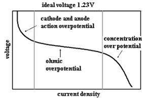
Figure 2. Single cell polarization curve
The efficiency of a fuel cell is another advantage over internal combustion engines, which are limited by the Carnot cycle efficiency. The efficiency of a fuel cell is limited to 40-50% range due to the direct conversion from chemical to electrical energy. Power gets lost is in the form of heat, which can be got back relatively easily and put to use. A big advantage with PEMFCs is Co-generation.
A converter which converts low level DC voltage into high level DC voltage is called DC- DC Boost. In this paper, a fuel cell is used as a DC source, in general, the output of fuel cell is small. In order to maximize or to enhance the fuel cell output, a boost converter is used [9]. It normally operates either in continuous conduction mode [10] or in discontinuous conduction mode. In this paper, boost converter operates in Continuous Conduction Mode (CCM) as shown in Figure 3.
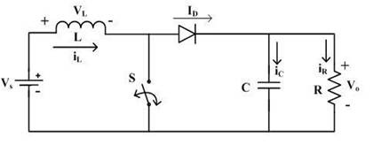
Figure 3. DC-DC Boost Converter Circuit Diagram
CCM involves two step processes to get power transferred from source to load. Inductor stores the energy when the switch 'S' is turned ON, and its equivalent circuit is shown in Figure 4 (a). Stored energy gets transferred to load through diode when the switch 'S' is turned OFF and its equivalent circuit is shown in Figure 4 (b). Also equivalent waveforms of voltage across an inductor, current through diode, current through inductor, and capacitor current are shown in Figure 5.
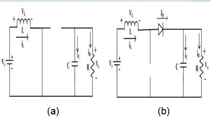
Figure 4. (a) DC-DC Boost converter with on and off (b) state circuit Diagrams
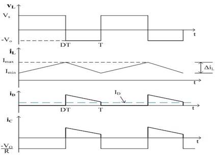
Figure 5. Current and voltage waveforms of DC-DC Boost Converter
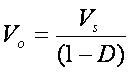
The relation between input voltage and load voltage for an ideal DC-DC Boost Converter, is given by
To obtain desired regulated output voltage from the dc-dc boost converter which feeds to inverter, double lead integral controller is designed to achieve minimum closed loop stability margins [11].
The boost converter operates in CCM for L>Lb where
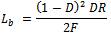
For D=0.8, R=10Ω and f=100 KHz, the boundary value of inductance is Lb=0.055mH.
The current supplied to the output RC circuit is discontinuous [12]. Thus a large filter capacitor is required to limit the output voltage ripple. The filter capacitor must provide the output DC current to the load when the diode D is off. The minimum value of the filter capacitor that results in the voltage ripple Vr is given by

At D=0.8, Vr / Vo=2%, R=10Ω and f=100KHz the minimum capacitance for the boost converter is Cmin = 0.0159mF.
Hybrid multilevel inverter (HMI) with a single SDCS is suitable for the applications in electrical vehicle applications. The main objective of HMI is, to combine this model with the renewable energy systems for a high power application [13]. Both IGBT and IGCT inverter switching pattern is developed with low switching losses.
The proposed hybrid multilevel inverter has the less number of switches compared to a conventional cascaded multilevel inverter. The hybrid multilevel inverter consists of two types of inverters, a conventional three phase six switches inverter and a single phase four switches H-bridge inverter. There upon, two SDCS is used to supply both the inverters.
The topology of the proposed hybrid multilevel inverter is shown in Figure 6, which includes a complete and a simplified single-phase topology. The bottom is one leg of a standard 3- leg inverter with a dc power source. The top is an H-bridge in series with each standard inverter leg. The Hbridge can use a capacitor, battery or other dc power source. The output voltage v1 of this leg (with respect to the ground) is either +Vdc/2 (S5 closed) or −Vdc/2 (S6 closed).This leg is connected in series with a full H-bridge, which in turn is supplied by a capacitor voltage. If the capacitor is used and kept charged to Vdc/2, then the output voltage of the H-bridge can take on the values +Vdc/2 (S1, S4 closed), 0 (S1, S2 closed or S3, S4 closed), or −Vdc/2 (S2, S3 closed). The capacitor's voltage regulation control method consists of monitoring the output current and the capacitor voltage so that during periods of zero voltage output, either the switches S1, S4, and S6 are closed or the switches S2, S3, S5 are closed depending on whether it is necessary to charge or discharge the capacitor.
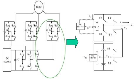
Figure 6. Topology of the hybrid multilevel inverter
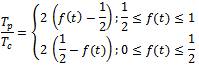
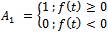
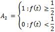
From the above discussion it should be noticed that the main inverter has three legs, six-switches and working on square wave mode, whereas the auxiliary or H-bridge inverter has four-switches and working on PWM mode. In general, PWM signals are generated with a single chip having only one carrier signal accompanied by six PWM channels, but in this proposal, HMI involves 12 PWM channels, because of main and auxiliary inverters. Thereafter the reference signal of SPWM used for auxiliary inverter is modified by using equations (4)-(7).
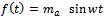
Where f(t) is a reference signal
Ma is modulation index
Tp /Tc is pulse width of PWM
A1 multiplexing signal
A2 multiplexing signal
The proposed PWM paradigm is shown in Figure 7. Where (a) is output phase voltage which is the sum of both auxiliary and main inverters output voltage. (b) is auxiliary inverter (conventional three phase six switch inverter) and main inverter (single phase four switch H-bridge inverter) output voltages, (c) is modulation signals of both main and auxiliary inverters.
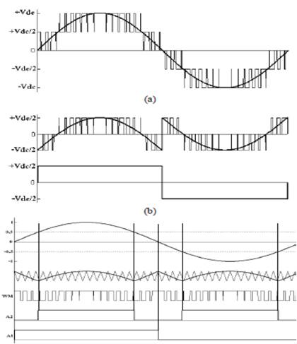
Figure 7. Proposed PWM paradigm: (a) output phase voltage, (b) auxiliary and main inverter output voltages and (c) modulation signals of both main and auxiliary inverter
In the recent years, the control of high performance induction motor drives for general industry applications and production automation has received widespread research interests. Induction machine modeling has continuously attracted the attention of researches not only because such machines are made and used in largest numbers, but also due to their varied modes of operation both under steady and dynamic states. Traditionally, DC motors were the work houses for the adjustable speed drives (ASDs) due to their excellent speed and torque response. But, they have the inherent disadvantage of commutator and mechanical brushes, which undergo wear and tear with the passage of time. In most cases, AC motors are preferred to DC motors, in particular, an induction motor due to its low cost, low maintenance, lower weight, higher efficiency, improved ruggedness and reliability. All these features make the use of induction motors a mandatory in many areas of industrial applications. The advancement in power electronics and semiconductor devices is in order to achieve a smooth, continuous and low total harmonic distortion (THD).
Three phase induction motors are commonly used in many industries and they have three phase stator and rotor winding. The stator windings are supplied with balanced three phase ac voltages, which produce induced voltage in rotor windings due to transformer action. It is possible to arrange the distribution of stator windings so that there is an effect of multiple poles, producing several cycles of magneto motive force (mmf) around the air gap. In this paper, three phase induction motor as a load, the equivalent circuit for one phase of the rotor is shown in Figure 8.
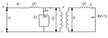
Figure 8. Steadystate equivalent circuit of an induction motor
The complete circuit model with all parameters referred to the stator is shown in Figure 9. Where Rs and Xs are the per phase resistance and leakage reactance of the stator winding. Xm represents the magnetic reactance. There will be stator core loss, when the supply is connected and the rotor core loss depends on the slip.
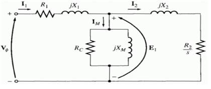
Figure 9. Equivalent circuit reference to stator
Simulation result of the proposed PWM scheme is shown in Figure 10.
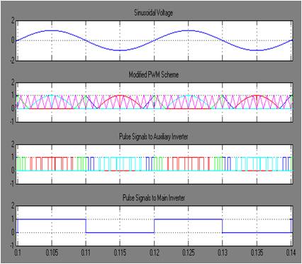
Figure 10. Proposed PWM scheme
The Matlab/Simulink model of three phase hybrid cascaded multilevel inverter is shown in Figure 11. and main inverter, auxiliary inverter and output phase voltage waveform and five level output phase voltage waveform of hybrid cascaded multilevel inverter and three phase five level output voltage waveform of hybrid cascaded multilevel inverter are shown in Figures 12, 13 and 14 respectively.
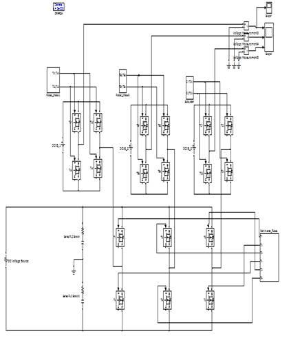
Figure 11. Matlab/Simulink model of three phase hybrid cascaded multilevel inverter.
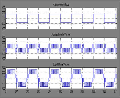
Figure 12. Main Inverter, Auxiliary Inverter and output phase voltage
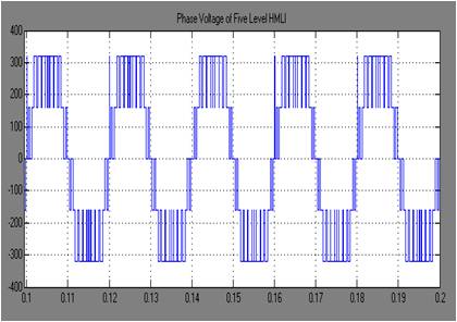
Figure 13. Five Level Output Phase Voltage of hybrid multilevel inverter
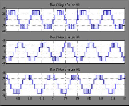
Figure 14. Three phase five level voltages of hybrid multilevel inverter.
The output voltage of boost converter by using fuel cell as DC source is shown in Figure 15.
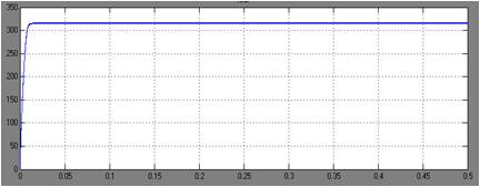
Figure 15. Output Voltage of boost converter
Matlab/Simulink model of the three phase hybrid cascaded multilevel inverter applied to induction motor by using fuel cell as dc source in open loop is shown in Figure 16 for evaluating motor characterstics.
The speed, electromagnetic torque, of the three phase hybrid cascaded multilevel inverter applied to induction motor is shown in Figures 17 and 18 respectively.
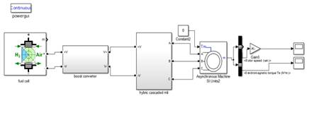
Figure 16. Matlab/Simulink model of three phase hybrid cascaded multilevel inverter applied to induction motor by using fuel cell as dc source (open loop).
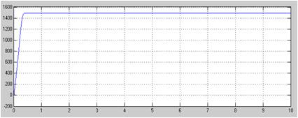
Figure 17. Speed of induction motor drive
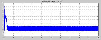
Figure 18. Electromagnetic Torque of induction motor drive.
Matlab/Simulink model of the three phase hybrid cascaded multilevel inverter applied to induction motor by using fuel cell as dc source in closed loop is shown in Figure 19 for evaluating speed of the induction motor.
The speed of induction motor at 1500 and 1400 rpm is shown in Figures 20, 21 respectively.
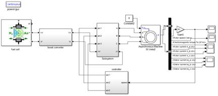
Figure 19. Matlab/Simulink model of three phase hybrid cascaded multilevel inverter applied to induction motor by using fuel cell as dc source (closed loop)
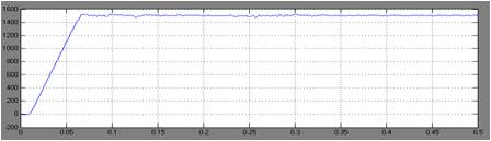
Figure 20. Speed of induction motor drive (at 1500 rpm)
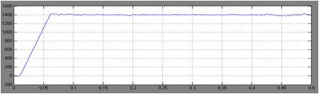
Figure 21. Speed of induction motor drive (at 1400 rpm)
THD analysis for cascaded and hybrid cascaded mli is shown in Figures 22 and 23 respectively. The proposed hybrid cascaded multilevel inverter has less THD value when compared to conventional cascaded multilevel inverter.
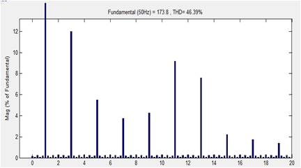
Figure 22. THD analysis for cascaded MLI
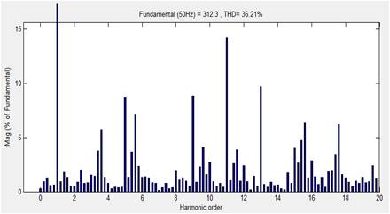
Figure 23. THD analysis for hybrid cascaded MLI
%THD for different values of mf , ma for CMI and HMI are shown in Table 1 and 2 respectively.
The proposed HMI for mf =21 and ma =1 and the % THD is found to be 34.74 in Table 2 which is comparatively less than the value of CMI i.e., 36.21 in Table 1.
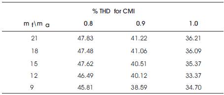
Table 1. % THD for CMI
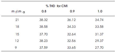
Table 2. % THD for HMI
The hybrid cascaded multilevel inverter is applied to induction motor by using fuel cell as dc source and it can be seen that the drive characteristics and speed of the induction motor is controlled. The modified PWM technique has also been developed to reduce the switching losses. Also, the proposed topology can reduce the number of required power switches and THD value when compared to conventional cascaded multilevel inverter. Simulation results have been performed. The switching losses of the hybrid multilevel inverter are less than the conventional cascaded multilevel inverter; consequently, system efficiency would be improved. The result shows that this alternative hybrid cascaded multilevel inverter can be applied for high power applications and can be used to interface with renewable energy sources.