
Figure 1. Basic Floating Point Multiplier
The floating point multiplier design is crucial for most applications like in GPUs. The designs are usually error prone. So the systems are developed to be error tolerant. The basic problem in floating point units is accuracy configuration. As accuracy plays a major role in many applications like rocket launches, the accuracy can be configured by using a log path rather than full path. Even though the error percentage increases in log path, the FP multiplier can be configured to have low power dissipation and area. The designs are developed using Verilog HDL and are functionally verified using ISIM simulator. The synthesis of the double Precision Multiplier is carried out in Xilinx ISE synthesizer and the results proved to be optimized in terms of delay and area.
Floating point multiplication is one of the most frequently used arithmetic operations in a wide variety of applications, but the high power consumption of the IEEE- 754 standard floating point multiplier prohibits its implementation in many low power systems, such as wireless sensors and other battery-powered embedded systems, and limits performance scaling in high performance systems, such as CPUs and GPGPUs for scientific computation. Floating point units provide high precision, a wide dynamic range of real values, and a much simplified programming model compared to the fixed point. The performance of floating point operations in a system, often represented as FLOPS (floating point operations per second), has become one of the most important performance metrics in modern computing system such as multi-core processors, GPUs, and supercomputers.
The power consumption of this architecture can be as high as 250W, due in large part to the sheer complexity of the IEEE-754 compliant hardware and its high activity factors during floating point operations, limiting further performance scaling of floating point operations. Even when floating point performance is not the focus, the complexity and associated power consumption of IEEEBy 754 compliant FPUs make floating point operations impractical for many low power embedded systems.
The IHW methodology seeks to improve power, area, latency, and related nonfunctional metrics through the use of accuracy tradeoffs in applications that can tolerate relaxed correctness specifications. However, many floating point applications in multimedia and scientific computing can tolerate imprecise computation, and the large power consumption of floating point multipliers presents an opportunity for significant power savings.
A low-power accuracy-configurable floating point multiplier ( Hang Zhang, Wei Zhang and John Lach , pp.48- 54) is proposed that is capable of achieving significant delay power reductions for single and double precisions compared to the IEEE-754 counter-parts. An analysis demonstrates that it is suboptimal to directly apply bit truncation schemes to the power hungry mantissa multiplication in the power-quality trade-off design space. The proposed low power accuracy configurable floating point multiplier applies bit truncation schemes on top of a Mitchell's algorithm based mantissa multiplication block, allowing an order of magnitude power reduction but with a smaller error percentage.
The proposed FP multiplier is inherently imprecise. Therefore, for applications that are partially error tolerant such as Ray Tracing, a “precise” FP multiplier is still required for obtaining an acceptable QOR, And the mantissa multiplication results in sub optimal power-quality trade-offs since the error increases exponentially while the power reduces linearly with the truncation bit length. Some future work Include integrating the “precise” mode into the FP multiplier and developing an automatic quality tuning model for applications that are partially error tolerant.
This paper is organized as follows: Floating Point Arithmetic operations are discussed in section 1. The exceptional cases are discussed in Section 2, Section 3 describes the accuracy problems and methods to overcome them. Section 4 discusses the existing floating point multiplier, the proposed multiplier is discussed in Section 5. The results are discussed in Section 6 and finally the paper is concluded.
For ease of presentation and understanding, decimal radix with 7 digit precision will be used in the examples, as in the IEEE 754 decimal 32 format. The fundamental principles are the same in any radix or precision, except that normalization is optional (it does not affect the numerical value of the result) ( Goldberg, David , pp. 5-48). Here, s denotes the mantissa and e denotes the exponent.
A simple method to add floating-point numbers is to first represent them with the same exponent. In the example below, the second number is shifted right by three digits, and we then proceed with the usual addition method:
123456.7 = 1.234567 × 10^5
101.7654 = 1.017654 × 10^2 = 0.001017654×10^5
Hence:
123456.7 + 101.7654
= (1.234567 × 10^5) + (1.017654 × 10^2)
= (1.234567 × 10^5) + (0.001017654 × 10^5)
= (1.234567 + 0.001017654) × 10^5
= 1.235584654 × 10^5
In detail:
e=5; s=1.234567 (123456.7) + e=2; s=1.017654 (101.7654)
e=5; s=1.234567 + e=5; s=0.001017654 (after shifting)
e=5; s=1.235584654 (true sum: 123558.4654)
This is the true result, the exact sum of the operands. It will be rounded to seven digits and then normalized if necessary. The final result is
e=5; s=1.235585 (final sum: 123558.5)
Note that the low 3 digits of the second operand (654) are essentially lost. This is round-off error. In extreme cases, the sum of two non-zero numbers may be equal to one of them:
e=5; s=1.234567 + e=−3; s=9.876543
e=5; s=1.234567+ e=5; s=0.00000009876543 (after shifting)
e=5; s=1.23456709876543 (true sum)
e=5; s=1.234567 (after rounding/normalization)
Another problem of loss of significance occurs when two close numbers are subtracted. In the following example e = 5; s = 1.234571 and e = 5; s = 1.234567 are representations of the rationales 123457.1467 and 123456.659.
e=5; s=1.234571 − e=5; s=1.234567 --------------- e=5; s=0.000004
e=−1; s=4.000000 (after rounding/normalization)
The best representation of this difference is e = −1; s = 4.877000, which differs more than 20% from e = −1; s = 4.000000. In extreme cases, the final result may be zero even though an exact calculation may be several million. This cancellation illustrates the danger in assuming that all of the digits of a computed result are meaningful. Dealing with the consequences of these errors is a topic in numerical analysis, see also Accuracy problems.
To multiply, the mantissas are multiplied while the exponents are added, and the result is rounded and normalized.
e=3; s=4.734612 × e=5; s=5.417242 -------------------- e=8; s=25.648538980104 (true product) e=8; s=25.64854 (after rounding) e=9; s=2.564854 (after normalization)
Division is done similarly, but is more complicated. There are no cancellation or absorption problems with multiplication or division, though small errors may accumulate as operations are performed repeatedly ( S.Kobayashi and G.P Fettweis , pp.2009-2012). In practice, the way these operations are carried out in digital logic can be quite complex (such as Booth's multiplication algorithm and digital division) ( Irine Padma B.T, Suchitra. K , pp. 130- 137), for a fast, simple method, as in the Horner method.
Floating-point computation in a computer can run into three kinds of problems:
Prior to the IEEE standard, such conditions usually caused the program to terminate, or triggered some kind of trap that the programmer might be able to catch. How this worked was system-dependent, meaning that floatingpoint programs were not portable.
The original IEEE 754 standard (from 1984) took a first step towards a standard way for the IEEE 754 based operations to record that an error occurred. Here we are ignoring trapping (optional in the 1984 version) and "alternate exception handling modes" (replacing trapping in the 2008 version, but still optional), and just looking at the required default method of handling exceptions according to IEEE 754. Arithmetic exceptions are (by default) required to be recorded in "sticky" error indicator bits. They are "sticky" means that they are not reset by the next (arithmetic) operation, but stay set until explicitly reset. By default, an operation always returns a result according to specification without interrupting computation. For instance, 1/0 returns +∞, while also setting the divide-byzero error bit.
IEEE 754 specifies five arithmetic errors that are to be recorded in "sticky bits":
The fact that floating-point numbers cannot precisely represent all real numbers, and that floating-point operations cannot precisely represent true arithmetic operations, leads to many surprising situations. This is related to the finite precision with which computers generally represent numbers.
For example, the non-representability of 0.1 and 0.01 (in binary) means that the result of attempting to square 0.1 is neither 0.01 nor the representable number closest to it. In 24-bit (single precision) representation, 0.1 (decimal) was given previously as e = −4; s = 110011001100110011 001101, which is 0.100000001490116119384765625 exactly.
Squaring this number gives 0.01000000029802322609739917425031308084726333 6181640625 exactly.
Squaring it with single-precision floating-point hardware (with rounding) gives 0.010000000707805156707763671875 exactly.
But the representable number closest to 0.01 is 0.009999999776482582092285156250 exactly.
Also, the non-representability of π (and π/2) means that an attempted computation of tan(π/2) will not yield a result of infinity, nor will it even overflow. It is simply not possible for standard floating-point hardware to attempt to compute tan(π/2), because π/2 cannot be represented exactly.
In addition to loss of significance, inability to represent numbers such as π and 0.1 exactly, and other slight inaccuracies, the following phenomena may occur:
Because of the issues noted above, use of floating-point arithmetic can lead to many problems. The creation of thoroughly robust floating-point software is a complicated undertaking, and a good understanding of numerical analysis is essential. In addition to careful design of programs, careful handling by the compiler is required. Certain "optimizations" that compilers might make (for example, reordering operations) can work against the goals of well-behaved software. There is some controversy about the failings of compilers and language designs in this area. ( Gokul Govindu, Ling Zhuo, Seonil Choi, Viktor K. Prasanna , pp. 1-8) Binary floating-point arithmetic is at its best when it is simply being used to measure real-world quantities over a wide range of scales and at its worst when it is expected to model the interactions of quantities expressed as decimal strings that are expected to be exact. An example of the latter case is financial calculations. For this reason, financial software tends not to use a binary floating-point number representation (J.N. Mitchell , pp. 512-517). The "decimal" data type of the C# and Python programming languages, and the IEEE 754- 2008 decimal floating-point standard, are designed to avoid the problems of binary floating-point representations when applied to human-entered exact decimal values, and make the arithmetic always behave as expected when numbers are printed in decimal.
Small errors in floating-point arithmetic can grow when mathematical algorithms perform operations an enormous number of times. A few examples are matrix inversion, eigenvector computation, and differential equation solving. These algorithms must be very carefully designed if they are to work well. Computations may be rearranged in a way that is mathematically equivalent but less prone to error. As an example, Archimedes approximated π by calculating the perimeters of polygons inscribing and circumscribing a circle, starting with hexagons, and successively doubling the number of sides.
There are different types of algorithms that can be used for the mantissa multiplication block. But the overall approach for two floating point numbers to be multiplied is same. The basic algorithm used for multiplying Double-Precision floating point numbers is shown in Figure 1.
Figure 1. Basic Floating Point Multiplier
The floating point multiplication ( Gokul Govindu, Ling Zhuo, Seonil Choi, Viktor K. Prasanna , pp. 1-8) is carried out in three parts.
1. In the first part, the sign of the product is determined by performing an Ex-or operation on the sign bits of the two operands.
2. In the second part, the exponent bits of the operands are passed to an 8-bit adder stage and a bias of 127 is subtracted from the obtained output.
3. In the third part and most important stage, the product of the mantissa bits is obtained. The 24-bit mantissa multiplication was done by normal one-to-one multiplication. A barrel shifter is also used in the succeeding section, normalization.
As an example consider two floating point numbers a = - 18.0 and b = +9.5
Expected floating point product = (-18.0) x (+9.5) = -171.0
a = -10010.0 = - 00010010.0 = - 1.00100000000000000000000 x 24
b = +1001.1 = + 00001001.1 = + 1.00110000000000000000000 x 23
Sign of a = 1 = s_a
Sign of b =0 = s_b
Biased exponent of a = 127 + 4 = 131 =10000011 = e_a
Biased exponent of b = 127 + 3 = 134 =10000010 = e_b
Mantissa of a = 00100000000000000000000 = mant_a
Mantissa of b = 00110000000000000000000 = mant_b
fp_a = 1 10000011 00100000000000000000000 = C1900000h
fp_b = 0 10000010 00110000000000000000000 = 41180000h
s_out = s_a xor s_b = 1 xor 0 =1
Step1: Add e_a and e_b to get the sum
10000011 + 10000010 =1 00000101
Step 2: Bias of 127 is subtracted from the sum to exponent of the output
100000101– 01111111 = 10000110 = e_out
Step 1: Extract both the mantissas by adding 1 as MSB for normalization to form 24-bit mantissas
24-bit mant_a = 100100000000000000000000
24-bit mant_b = 100110000000000000000000
Step 2: Multiply 24-bit mant_a and mant_b to get 48-bit product.
(100100000000000000000000) X (100110000000000000000000) =010101011000000000 000000000000000000000000000000
Leading 1 of the 48-bit is found and the remaining bits are truncated to 23-bit output mantissa value to get the mantissa of the output.
m_out = 01010110000000000000000
e_out =100000110
Floating Point Product (in binary) = 1 10000110 01010110000000000000000=C32B0000h
Biased exponent = 10000110 =134
Unbiased exponent =134 - 127 = 7
Floating Point Product (in decimal) = - 1. 01010110000000000000000x 27 = - 10101011.0000000000000000 = -171 .0
The proposed design mainly concentrates on the low power consumption with accuracy configurations for single precision floating point multiplier. For accuracy configurations we are declaring two paths. They are full path and log path. For log path, the authors are going to obtain accuracy configuration by truncating number of bits from mantissa. For example, 19 bits in the single precision mantissa multiplication, the proposed FP multiplier is able to achieve 26X power reductions with a maximum error percentage of 18%, while truncating 21bits directly in the FP multiplier produces about 21%maximum error but only gains 2.3X power reduction. Here they have implemented the system with truncating the truncating 18 bits in mantissa. The total block contains ex-or gate for sign bit, 8 bit adder for exponent addition, bit truncation block, 23 bit adder for mantissa addition, adder for out of bit truncation block, exceptions and packing block.
The Proposed Floating Point multiplier design is shown in Figure 2. 64-bit input operands are supplied to the architecture. The selection line for choosing path whether log path or full path, depending on accuracy is what we need. For full path, we get maximum error 2.03% and for log path it is 11.11%. For path selection we use one single bit. For full path, it is logic 0 and logic 1 for log path. Depending on accuracy, we need we choose the path.
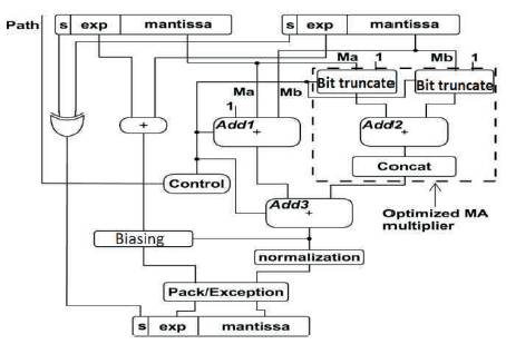
Figure 2. Proposed Floating Point Multiplier
The block diagram shown in Figure 2 is a low power accuracy configurable floating point multiplier. As shown in Figure, Sign (63) bit of 64-bit input operands are supplied to the architecture and is processed with ex-or gate. If two inputs are positive numbers, the result will be positive and if two inputs are negative, the result will be positive. Any input that is combination of negative and positive, the result will be negative. So this can be achieved by ex-or gate.
Exponents (62-52) bits are added with 11 bit adder. This result is the exponent of final multiplication. This can be normalized at final result. Biasing can be unbiased at the end, so that the result can be pure exponent.
Mantissas (0-51) are added so that we can achieve multiplication with help of adder. These can be achieved either in log path or full path. The process depends on the path we choose.
Packing ( Jaenicke and W. Luk , pp. 897-900) is the process of converting a 64 bit to 128 bit by appending zeros to MSB side of 64 bit. When we work with 64 bit system but the code we build is 64 bit, then the system is incompatible. So, we need packing. Final result will be concatenated with sign, exponent and mantissa.
In full path, multiplication mantissas are added by a 52 bit adder. The two mantissas are passed through the bit truncation block. The output of bit truncation block is of 10 bits. The two outputs from bit truncation blocks get added by the 10 bit adder. Concatenation is for appending zeros at the MSB side of the result, so that it will get 52 bit.
The output from concatenation block is added with output from a mantissa adder with 52 bit adder. Fraction multiplication of Ma*Mb with an additional adder for (1 + Ma + Mb).Finally this will be the mantissa result. The path involved in floating point multiplication during full path is shown in Figure 3.
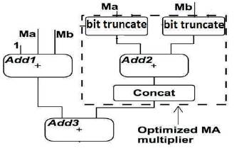
Figure 3. Full path Multiplication
When the multiplier is configured to the log path, Add1 and Add3 are set idle by multiplexing all inputs to constant 0. And Add3 is effectively bypassed by a set of multiplexers. In this case, Add1 and Add3 consume only the leakage power.
In log path, two mantissas are passed through bit truncation block. ( Burgess. N.; Knowles, S ., pp. 1489-1493) The output of bit truncation block is of 10 bits. The two outputs from bit truncation blocks get added by the 10 bit adder. Concatenation is for appending zeros at the LSB side of the result. This will be the final result. Mantissa multiplication (1+Ma)(1+Mb). The block diagram for log path multiplication is shown in Figure 4.
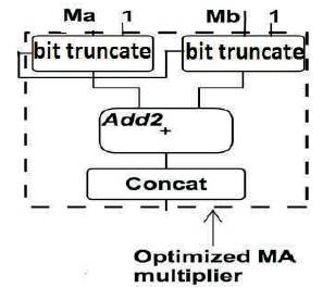
Figure 4. Log Path Multiplication
By truncating19 bits in the single precision mantissa multiplication, the proposed FP multiplier is able to achieve 26X power reductions with a maximum error percentage of 18%, while truncating 21 bits directly in the “Precise” FP multiplier produces about 21% maximum error, but only gains 2.3X power reduction. ( M. Schmookler and D. Mikan ) ( E. Hokenek and R. K. Montoye , pp.71-77) During the operation of the full path configuration, all three adders are switching, providing about 2X the power reduction compared to its single precision IEEE-754 counterpart. It's necessary to point out that part of the power savings of the accuracy configurable FP multiplier comes from the elimination of the rounding unit, which consumes around 18% power consumption according to ( Gokul Govindu, Ling Zhuo, Seonil Choi, Viktor K. Prasanna , pp. 1-8).
The double Precision floating point multiplier functionality for both full path and log path separately and the corresponding results are as shown in the figures below. The tool used is the Xilinx ISIM Simulator. The synthesized RTL schematics for the target device Spartan 3E (XC3S500e- 5fg320) are shown in Figure 6 and Figure 8 respectively.
Figure 5 shows the RTL schematic of Full Path multiplication method. When the two inputs A and B each of length 64 bits are given to the FP multiplier, then the 52 bit mantissa will pass through the bit truncation blocks for the truncation of lower 18 bits. This is again passed through the concatenation block for appending the 42 zeros on MSB side of mantissa. Later this 52 bit mantissas of A and B are added and the 52 bit mantissa is obtained from the other path i.e. through other adder is added to get the final mantissa of C i.e. output. The MSBs of A and B are sent through XOR block to get the resultant MSB. The remaining bits of A and B i.e. from 62 to 52 bit positions of each input is sent through the 11 bit adder to get the resultant exponent.
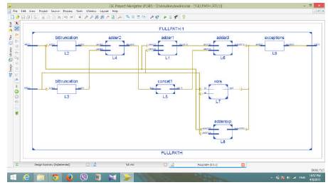
Figure 5. RTL Schematic of Full Path Multiplication
Figure 6 shows the design summary of full path multiplication method used to multiply the two inputs. It can be seen from the table that the number of 4 input LUTs used in the process are only 95, number of slices occupied is 49. The delay is 14.276ns.
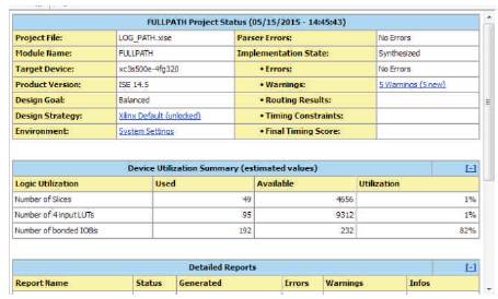
Figure 6. Design Summary of Full Path Multiplication
Figure 7 shows the RTL schematic of Log Path multiplication method. When the two inputs A and B each of length 64 bits are given to the FP multiplier, then the 52 bit mantissa will pass through the bit truncation blocks for the truncation of lower 42 bits. This is passed through the concatenation block for appending the 42 zeros on LSB side of mantissa. Later, this 52 bit mantissas of A and B are added to get the final mantissa of C i.e. output. The MSBs of A and B are sent through XOR block to get the resultant MSB. The remaining bits of A and B i.e. from 62 to 52 bit positions of each input is sent through the 11 bit adder to get the resultant exponent.
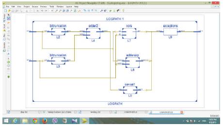
Figure 7. RTL schematic of Log Path Multiplication
Figure 8 shows the design summary of full path multiplication method used to multiply the two inputs. It can be seen from the table that the number of 4 input LUTs used in the process are only 42, number of slices occupied is 23. The delay is 10.516ns.
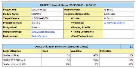
Figure 8. Design Summary of Log Path Multiplication
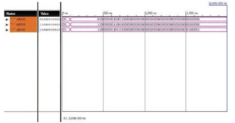
Figure 9. Simulation Output of Full Path Multiplication
The simulation output of log path multiplication as shown in Figure 10 is described as follows. The inputs A and B are 64- bit operands. i.e., A=1100000000110010000000000 00000 0000000000000000000000000000000000 and B=0100 0000001000110000000000000000000000000 00000000000000000000000. Then the output C is also a 64-bit operand whose value is C=11000 0000110 0101000010000000000000000000000000000000 000000000000 in binary values. But, in decimal values, the corresponding values are A=-18, B= +9.5 and Output C= -168.25. The error in log path is 1.6%.
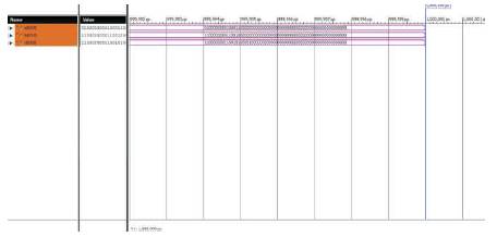
Figure 10. Simulation Output of Log Path Multiplication
Table 1 shows that the floating point multiplier can be designed using both full path and log path designs. The results convey that if the error in design is tolerable, then the log path based multiplication is best suited for error tolerant applications.
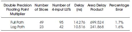
Table 1. Comparison of Full Path and Log Path Multiplication
The efficient design of multipliers is important in any high performance arithmetic unit. As the designs can be developed to configure accuracy, a log path and full path based designs are developed for single precision floating point multiplier. This paper implements a low power accuracy configurable floating point multiplier and demonstrates that dramatic power reductions could be achieved when applying bit truncations on top of the algorithmic transformed FP multiplier. The wide range of accuracy configurations allows fine grained quality tuning for various error tolerant applications. One limitation of the proposed FP multiplier is that it is inherently imprecise. Therefore, for applications that are partly error tolerant such as Ray Tracing, a “precise” FP multiplier is still required for obtaining an acceptable QoR. The error was found to be as low as 1.6% for log path and 1.7% for full path. Hence if accuracy along with low area and less delay is required, then Log Path based multiplication can be used.