(1)
Microwave radar requires the development of pulse generators that are capable of producing a succession of pulses in very short time durations. The generation of radar transmitter requires high-power and high-voltage pulses, whereas the indicator and ranging circuits require pulses of negligible power and relatively low voltage. This paper presents a pulse generator which is designed by using edge generator circuit with edge tuning capability. The pulse generator circuit obtained generates the pulses dissipating power which is less when compared to CMOS (Complementary Metal Oxide Semiconductor) logic. It is an energy efficient circuit which can be implemented in HSPICE using 0.18μm CMOS standard process technology.
Energy harvesting is a technique that can capture an effective power source, such as a small energy present in vibration, heat and electromagnetic waves. This technique is expected to be useful for making some applications (e.g. health monitoring in plant, building automation and sensor network). However, the energy obtained from power resources is weak, and also the value of voltage/current is low-level, so that the logic circuit for energy harvesting is required to reduce the power consumption.
Switching power consumption refers to the power consumption due to the charging and discharging of a capacitance, 'C' and expressed as where 'f ' is operation switching frequency and 'a' is the switching activity factor. The switching activity factor is the probability that a node makes a transition from 0 to 1.
In an inverter, when the output makes a transition from 0-> VDD , the dynamic energy drawn from the power supply in one cycle is
For this transition, the stored energy in the load capacitance is
This means that during this transition, 50% of the total energy drawn from the supply is consumed by the PMOS transistor. For the output transition VDD -> 0, the stored energy in the capacitor is consumed by the NMOS transistor and no energy is drawn from the power supply.
A pulse generator is either an electronic circuit or a piece of electronic test equipment used to generate rectangular pulses (Pulse Generator). In general, pulse generators of a radar system is classified into two types, namely, those that are associated with the transmitter and those that are used in the indicator and ranging circuits. The principal distinguishing feature of pulse generators of these two types is the output power level. The power pulse generators used in the transmitters of radar systems have been variously referred to as “modulators,” ''pulsers,” and 'keyers.”
Here the pulse generator circuit is implemented using edge generator circuit. The executed pulse generator circuit is compared using the proposed subthreshold adiabatic logic based generator circuit.
The core component of the pulse generator is the edge generator, as shown in Figure 1 (Xubo Wang, Anh Dinh and Daniel Teng, 2012). Gaussian pulse is generated by the edge generator. Here each rising edge of the Vtrigger triggers positively-peaked pulses through a NOR gate and negatively-peaked pulse through a NAND gate. The two parameters pulse amplitude and pulse width are controlled by the delay elements. The principle behind pulse generation logic is that when one XOR input is slower than the other XOR input, then the time difference between these two inputs produces a positive distributed voltage pulse (usually represented by Gaussian distribution), when the inverted NAND (AND) input is slower than the other NAND input then the time difference between these two inputs produces a voltage pulse which is negative distributed. Control (ctrl) signal controls the polarity of the edge generator output. The ctrl signal selects either the positive pulse or the negative pulse to pass the output through the AND and OR logic gates. The Gaussian derivative pulse generator, as shown in Figure 2, consists of an array of edge generators which are connected in parallel manner. Each edge generator produces a single pulse with different amplitude and the same pulse width Tdelay . The adjustment of delay in each edge generator is based on the shape factor of the tenth derivative of the Gaussian pulse. The control signal produces pulses with negative polarity. This can be achieved by inverting the control signal at the second, fourth, sixth and eighth edge generators.
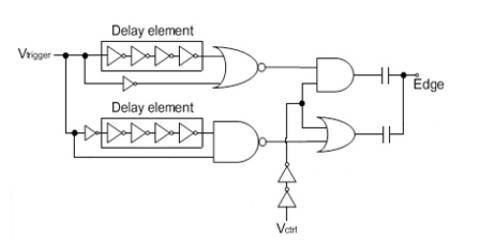
Figure 1. Edge generator circuit with edge tuning capability
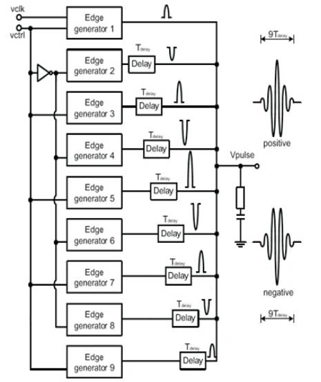
Figure 2. Block diagram of the pulse generator
In order to achieve low power and energy efficient VLSI (Very Large Scale Integration) circuits, different multiplication algorithms (Tunga Mounika, Duvvuru Praveen kumar, M. Bharathi, 2014) will be used to illustrate methods for designing different cells.
The proposed system (Yasuhiro Takahashi and Toshikazu Sekine, 2014) uses a two phase clocking power supply which has different frequency and amplitude. For example, a 2-chain inverter circuit is shown in Figure 3. Figure 4 shows the timing chart for the circuit. It is necessary to switch on-off the input signal when VPC and  . The frequency of is twice, based on the frequency of VPC and the input signal frequency is 1/2. The amplitude of VPC and are 0–0.5V and 0–0.25V respectively. The frequencies of VPC and are 10kHz and 20kHz.
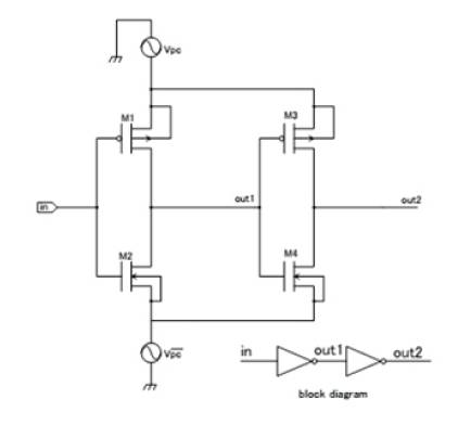
Figure 3. Cascaded inverter
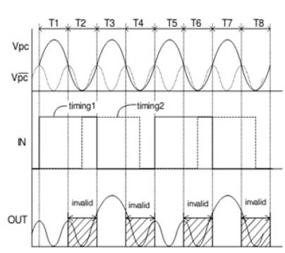
Figure 4. Timing Chart
These circuits were implemented and tested in HSPICE (Synopsys HSPICE RF Manual). The results are shown in Figures 5 & 6 which are obtained by simulating the code. The Power dissipated is compared and is tabulated. It is shown in Table 1.
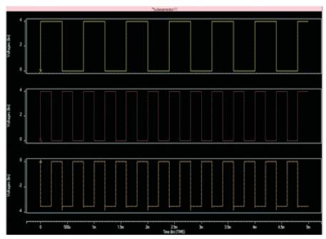
Figure 5. Pulse generator using CMOS logic
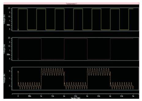
Figure 6. Pulse generator using Subthreshold Adiabatic Logic
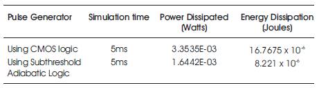
Table 1. Power Dissipation of Pulse generator
The Table 1 shows a comparison of power dissipation of pulse generator using CMOS logic and Subthreshold Adiabatic Logic. It also shows the Energy dissipation of respective technologies.
This paper presents an effective implementation of Pulse Generator circuit using two phase clocking subthreshold adiabatic logic. From the results, it can be concluded that by using two phase clocking subthreshold adiabatic logic, power dissipated is less. Also the circuit saves energy and it is energy efficient. This pulse generator circuit can be used in microwave radar applications (G. N. Glasoe). They can also be used to drive devices such as lasers, optical components, switches, modulators as well as resistive loads. The pulse generator's output may also be used as the modulation signal for a signal generator. This work can be extended in designing a Ultra Wide Band (UWB) Pulse generator that can be used in radar system.