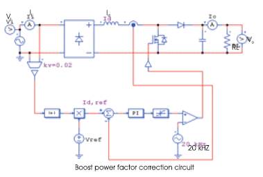
Figure 1. Conventional PFC open loop circuit
This paper uses the Bridgeless Rectifier Circuit, coupled with the Interleaved Boost and “PFC” (Power Factor Correction) technology to design a high-efficiency AC/DC conversion circuit, to provide a load of 400V, 2KW. The system efficiency can reach up to 96%. The power factor is close to 1, the input current ripple is below 0.8A and the output voltage ripple is below 6V. In addition to the application in variable- frequency control air-conditioning, the proposed system can also be used for a wide range of variable frequency control motors and DC electric motors, such as household fans, DC electronic fluorescent lamps or variable- frequency control motors.
Energy is fundamental to all Scientific and Technological development, as it brings about human progress and prosperity. Mankind is highly dependent on the use of energy[3].The efficiency, power factor, ripple current and cost are important elements in the present market. In conventional motor variable frequency drive technology, the AC power is rectified to DC power through a bridge rectifier, and then an oscillator generates variable frequency signals that trigger the power crystal to convert the DC current into an AC current with controllable frequency to drive the induction motor. The process of converting AC to DC needs to overcome problems such as low efficiency, a low power factor, a large input ripple current, a large output ripple voltage and unsuitability for providing a high current load [4]. Hence, this study proposed a new circuit structure using the coupled inductor design combined with bridgeless PFC technology and interleaved PFC to develop Bridgeless Interleaved Power Factor Correction (BIPFC).
A better PFC power supply circuit is needed for large capacity electrical loads. The designed PFC circuit specifications are based on the largest window-type air-conditioning on the market capacity of 2 tons, and its power requirement is about 2KW; [5]. The selected input voltage is in the range of 110V~220V, and the output voltage is increased to 400V to reduce the current load of the power supply lines, so that the design of the circuit can meet practicality. Therefore, the load resistor RL= 80Ω is selected as the design goal. Figure 1 represents the Conventional PFC open loop circuit.
Figure 1. Conventional PFC open loop circuit
In Figure 2 When S1 is on, the output voltage is provided by the current flowing through D2 and S4 , as shown by the solid lines in Figure 4. In Figure 3 When S2 is on, the output voltage is provided by the current flowing through D1 and S3 , as shown by the dotted lines in Figure 4. [6] .
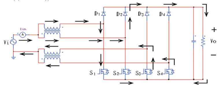
Figure 2. The current flow path (positive half-cycle) when S1 is on
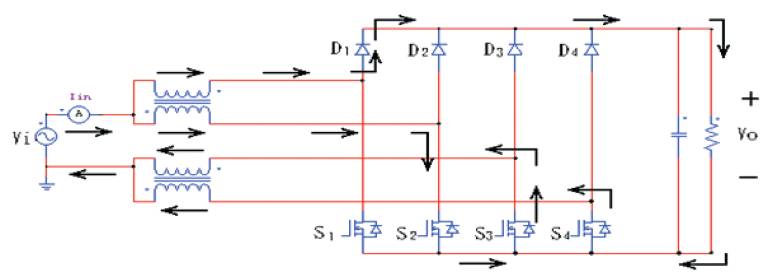
Figure 3. The current flow path (positive half-cycle) when S2 is on
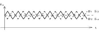
Figure 4. Output voltage ripple
The open-loop control circuit is as shown in Figure 5 [1]-[6] As seen, Vi(s) is the sinusoidal voltage of the input power, and Vref is the reference signal for the adjustment of the output voltage. By multiplying Vi(s) and Vref it is possible to get the values needed to determine the output voltage. Rectifier(+) and Rectifier(-) convert the sine wave into a positive half-cycle waveform with a phase gap of 180°, V i(+) is the positive half-cycle feedback current signal, Vi (--) is the negative half-cycle feedback current signal for the adjustment of the current and the input voltage in terms of waveform, and Vo(s) is the DC 400V output voltage. The closed-loop control circuit is as shown in Figure 6. In comparison to Figure 5, the reference signal Vref and the feedback voltage Vo(s) are modified before multiplying them with Vi(s) via the PI controller to ensure the stability of the output voltage.
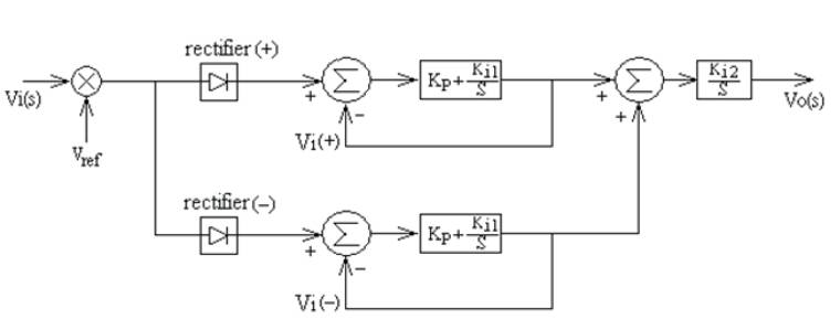
Figure 5. Bridgeless interleaved PFC open loop control box process
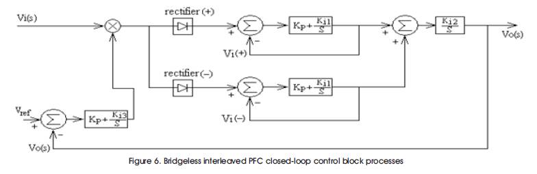
Figure 6. Bridgeless interleaved PFC closed-loop control block processes
This study designed a 220V circuit to boost the PFC by using double coupling inductors to switch frequency through the MOSFET, which consisted of the bridgeless interleaved PFC open-loop control circuit with 400V DC voltage output, as shown in Figure 7. [1] Although the bridgeless interleaved PFC open-loop control circuit is superior to the conventional PFC circuit and has many advantages, its tolerance is poor in the case of great changes to the load that result in unbearable voltage change rates. Therefore, the bridgeless interleaved PFC closed-loop control circuit, as shown in Figure 8, is needed to provide a stable supply to any load. [2] The circuit has a very stable output voltage. In this theory, it can maintain a set voltage output in the case of any load resistance. It is characterized by a high power factor, high efficiency and a low ripple current.
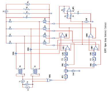
Figure 7. Bridgeless interleaved PFC open-loop control circuit (the main circuit and the control circuit
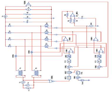
Figure 8. Bridgeless Interleaves PFC closed-loop control circuit (the main circuit and the control circuit)
The proposed design is an excellent variable frequency controller power supply with a high degree of operational stability and market competitiveness.
In the conventional PFC (single MOSFET boost) circuit (Figure 9). The results of simulating the capacity for a window type air conditioner of about 2000W are as shown in Figure 10, where Vi is the input voltage, Vo is the output voltage, and Ii is the input current. According to the simulation results, the maximum input voltage was 220V, the maximum input current was 19.5A, the output voltage was DC 400V, the power factor was close to 1, the output voltage ripple was 20V p-p, the input current ripple was 2.5Ap-p , the calculated efficiency was 0.93%, and the output p voltage was stabilized at 0.36 seconds. The simulation results for changing the load resistance to RL=180Ω are shown in Figure 10. The output voltage remained at 400V, the ripple voltage was reduced to Vr =4V, the input current was reduced to 6.7A, the ripple current Ir =1Ap-p , the efficiency η=90, and the power factor was close to 1. The simulation results for changing the output resistance to RL=580Ω are shown in Figure 11. The output voltage remained at 400V, the ripple voltage was reduced to Vr =0.5Vp-p , the input current was reduced to 1.9A, the ripple current Ir=0.6Ap-p , the efficiency η=92.8, and the power factor was close to 1. As seen, the proposed circuit was adaptive to any change in the load and could provide a stable and high quality DC power supply.
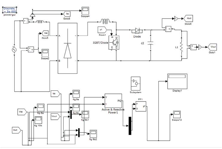
Figure 9. Conventional PFC open loop circuit
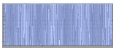
Figure 10. Simulation results of the conventional PFC control circuit current wave form
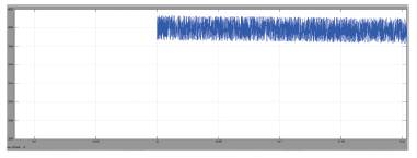
Figure11. Simulation results of the conventional PFC control circuit voltage wave form
The proposed open-loop bridgeless interleaved PFC circuit is shown in Figure 7. As shown in the figure, the parameters of controller PI1 are Gain 1, time constant 0.03. Parameters of PI2 and PI3 are Gain 2, time constant 0.03, parameters of Sum1~Sum3 are Gain (+) 1, Gain (-) -1, parameter of Vsen1 is Gain 0.02 The simulation results of providing the capacity for a 2000W window type air conditioner with the same capacitor and inductance parameters as the conventional PFC circuit are as shown in Figure 10, where Vi is the input voltage, Vo is the output voltage, and Ii is the input current. For the circuit Figure 12 According to the results, the maximum input voltage was 220V, the maximum input current was 19A, the output voltage was 400V DC, the power factor was close to 1, the output voltage ripple was 15Vp-p , the input current ripple was 2Ap-p , the calculated efficiency was 95.6%, and the output voltage was stabilized at 0.12 seconds (Figure 13 and 14).
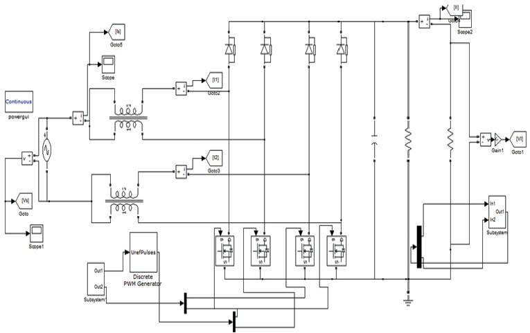
Figure 12. Open-loop bridgeless interleaved PFC circuit
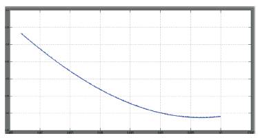
Figure 13. Open-loop bridgeless interleaved PFC circuit current wave form
Figure14. Open-loop bridgeless interleaved PFC circuit voltage wave form
The proposed closed-loop bridgeless interleaved PFC circuit is shown in Figure 8. Parameter of Vsen2 is Gain 0.03 The simulation results of providing the capacity for a 2000W window type air conditioner with the same load of 2000W (RL=80Ω) are shown in Figure 15.The output voltage was stabilized at 0.12 seconds. Figure 16 shows that the maximum input voltage was 220V, the maximum input current was 19A, the output voltage was DC 400V, and the power factor was close to 1. Figure 16 shows that the output voltage ripple was 12Vp-p . Figure 17 shows that the input current ripple was 1Ap-p and the calculated efficiency was 96%.
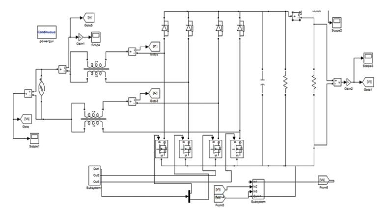
Figure 15. Closed-loop bridgeless interleaved PFC circuit
Figure 16. Simulation results of the closed-loop bridgeless interleaved PFC circuit current wave form
Figure 17. Simulation results of the closed-loop bridgeless interleaved PFC circuit voltage wave form
The proposed DC bridgeless interleaved PFC circuit was shown to have excellent performance by the simulation results. It was found to have good PFC functions, the input voltage and the input current were at the same phase: hence, the power factor approached 1. It reduces power loss and could improve the conversion efficiency by more than 94%. The interleaved switch boosting technology could reduce the input ripple current to 0.8A which is about one-fifth that of conventional circuits. The output ripple voltage was reduce by about one quarter as compared with the conventional circuits.