(1)

A high performance interleaved bi-directional dc–dc converter with zero voltage switching can convert low-voltage reversible power sources to a high voltage dc bus individually or simultaneously by the phase-shift control, and also can step down the high-voltage dc bus to charge the power sources. The reversible power sources can charge each other. The circuit is designed as half-bridge circuit. The inductors in the proposed converter are designed to operate in synchronous conduction mode for achieving turn-on zero-voltage-switching (ZVS) of all switches. The effectiveness of the designed circuit topology, ZVS properties and the goal of high- performance conversion can be obtained.
Electrical power systems in future uninterruptible power supplies or electrical vehicles may employ hybrid energy sources, such as fuel cells and super capacitors. An Interleaved Soft Switching Boost Converter (ISSBC) for a photovoltaic (PV) power-generation system is proposed. The topology used raises the efficiency for the dc/dc converter of the PV power conditioning system (PVPCS). It minimizes switching losses by adopting a resonant softswitching method[1]. A new three-input dc–dc boost converter interfaces two unidirectional input power ports and a bidirectional port for a storage element in a unified structure. This converter is interesting for hybridizing alternative energy sources such as photovoltaic (PV) source, fuel cell (FC) source, and battery. Supplying the output load, charging or discharging the battery can be made by the PV and the FC power sources individually or simultaneously. Due to interactions of converter control loops, decoupling network is used to design separate closed-loop controllers [2]. A novel interleaved boost converter with zero-voltage switching (ZVS) and zero-current switching (ZCS) .By using the interleaved approach, this topology not only decreases the current stress of the main circuit device, but also reduces the ripple of the input current and output voltage. Moreover, by establishing the common soft-switching module, the soft-switching interleaved converter can greatly reduce the size and cost. The main switches can achieve the characteristics of ZVS and ZCS simultaneously to reduce the switching loss and improve the efficiency with a wide range of load [3]. A level-shifting voltage-copier circuitry is introduced to convert one or two input voltage levels to eight voltage levels. A resonant inductor is further added to improve the performance of these circuits [4]. An integrated three-port bidirectional dc–dc converter for a dc distribution system is presented. A high-frequency transformer of the proposed converter not only provides galvanic isolation between energy sources and high voltage dc bus, but also helps to remove the leakage current resulted from PV panels. The MPPT (Management Power Point Tracking) and power flow regulations are realized by duty cycle control and phaseshift angle control, respectively [5]. A new zero-voltage switching (ZVS) isolated dc–dc converter combines a boost half-bridge (BHB) cell and a full-bridge (FB) cell, so that there are two different type of power sources[6]. A bidirectional isolated dc–dc converter controlled by phase-shift angle and duty cycle for the fuelcell hybrid energy system is analyzed and designed. The current-fed input can limit the input current ripple that is favorable for fuel cells. Moreover, a phase-shift and duty cycle modulation method is utilized to control the bidirectional power flow flexibly and it also makes the converter operate under a quasi-optimal condition over a wide input voltage range [7].
In all of these applications, we want to change the DC energy from one voltage level to another, while wasting as little as possible in the process. In other words, we want to perform the conversion with the highest possible efficiency. An important point to remember about all DCDC converters is that, like a transformer, they essentially just change the input energy into a different impedance level. So whatever the output voltage level, the output power all comes from the input; there’s no energy manufactured inside the converter. Quite the contrary, in fact some is inevitably used up by the converter circuitry and components in doing their job. We can therefore represent the basic power flow in a converter with this equation:
Where Pin is the power fed into the converter, Pout is the output power and Plosses is the power wasted inside the converter. Of course if we had a perfect converter, it would behave in the same way as a perfect transformer. There would be no losses.

Nowadays some types of converters achieve an efficiency of over 90%, using the latest components and circuit techniques. The proposed converter is operated at the dual power source step-up/step-down state, the primary input source V1 can step-down its voltage to charge the secondary power circuit, if the primary input voltage V1 is higher than the secondary input voltage V2. In the other way, the secondary input source V2 can step up its voltage to charge the primary power circuit. Figure 1 shows the System configuration of high performance interleaved bidirectional dc-dc converter. It contains three parts including a primary power circuit, a secondary power circuit, and an output circuit.
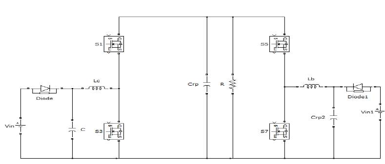
Figure 1.System configuration of high performance interleaved bidirectional dc-dc converter
Figure 2 shows a switch that operates with ZVS, has an antiparallel diode and a capacitor across it. If negative current is forced to flow through the antiparallel diode, then voltage across switch reduces to zero and then the switch is turned on with ZVS. During turn-off, the capacitor across switch reduces the rate of rise of voltage across device as current reduces to zero ZVS is preferred over ZCS, because with ZVS, the parasitic switch capacitance dissipates its energy into the load. If there were no ZVS, this parasitic capacitance would dissipate as heat in the switch which lowers the efficiency of the system. The converter employs another LC resonant circuit designed to resonate at switching frequency so that ZVS condition is achieved during both buck and boost operating modes. An interleaved boost converter via a resonant circuit to achieve soft switching, used the interleaved structure to reduce the input current ripple A multi device interleaved dc–dc converter interfaces the fuel cell with the power train of hybrid electric vehicles. The operation of hard switching and the huge reverse-recovery current within the output diode degrade the conversion efficiency as a traditional boost converter. The combination of two interleaved dc–dc converters into a dual-input interleaved dc–dc converter can simplify the circuit topology, improve the system performance, and reduce the manufacturing cost. The bidirectional converters for hybrid energy systems are connected with rechargeable battery modules, which can supply alone for supporting the output demand during the cold start period of the power source. These results in a huge input current when the system starts up. In order to smooth the in-rushing current, the studies of power converters with interleaved structure have received more attention recently.
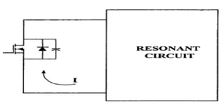
Figure 2. Zero Voltage Switching
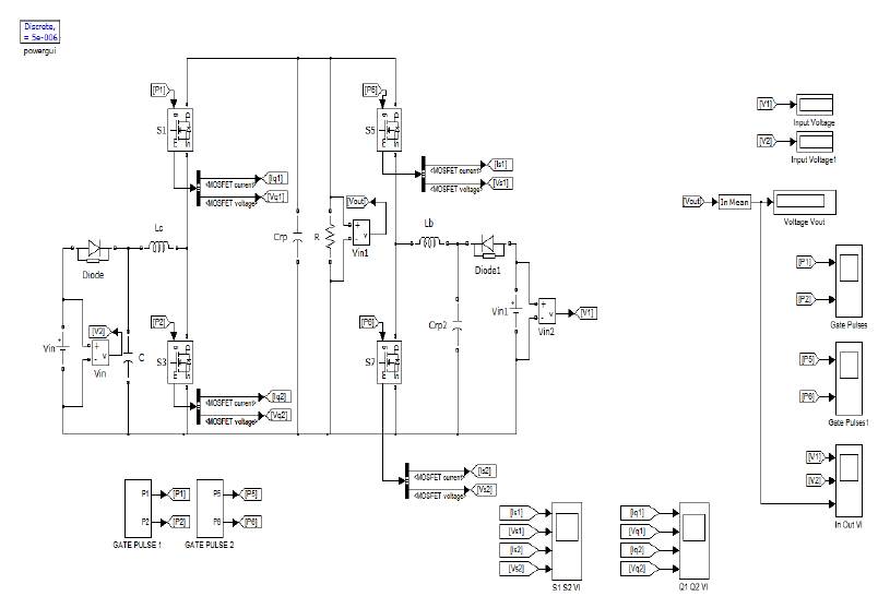
Figure 3.Simulation Circuit Diagram
The Matlab/simulink model of high performance interleaved dc–dc converter has been designed which is shown in Figure 3 and Generation of gate signal for the smooth transition (Figure 4) simulated in Matlab/ Simulink. Figure 5, Figure 6, Figure 7and Figure 8 illustrate the simulation results of gate pulse, voltage,current of switches and output voltage of proposed converter.
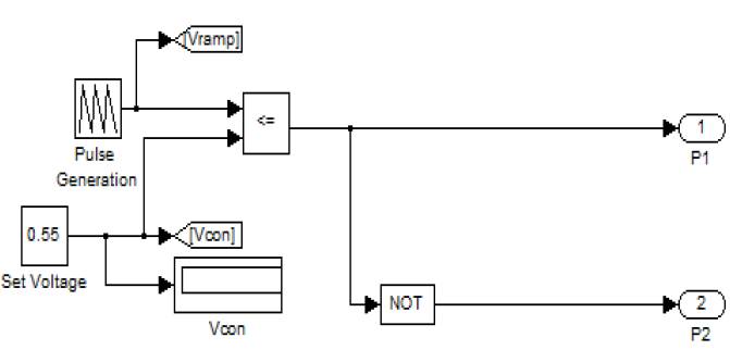
Figure 4.Generation of gate signal for the smooth transition
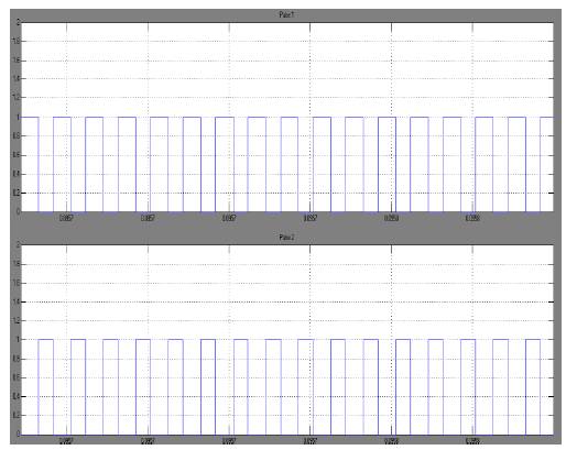
Figure 5. Gate Pulses
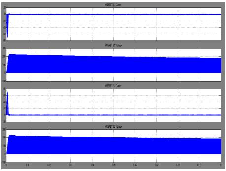
Figure 6. MOSFET S1 and S7 Voltage and Current Waveform
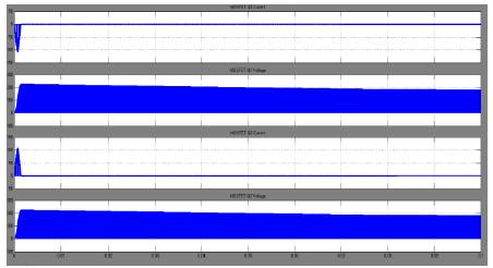
Figure 7. MOSFET S3 and S5 Voltage and Current Waveform
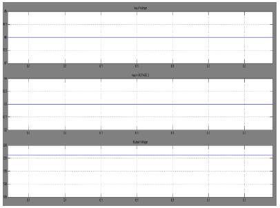
Figure 8. Input and Output Voltage
This study has successfully developed a high performance interleaved bi-directional dc-dc converter with zero voltage switching and the effectiveness of this converter is verified by experimental results of 200 V output for the different input voltage sources of V1=63, V2=48. According to the experimental results, all the inductors can be operated in the SCM, and all the switches are turned ON with ZVS. This new converter topology provides designers with an alternative choice to simultaneously convert hybrid reversible power sources. In addition, the proposed also can work well in high-power level applications because the switching loss, which is proportional to the square of the switch voltage, can be greatly reduced due to the ZVS property. In the design of half bridge dc -dc converter, the component count and cost get reduced.