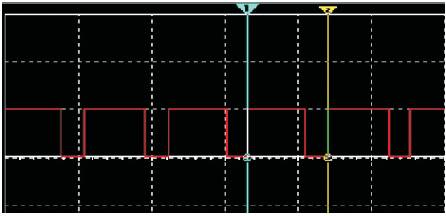
Figure 1. 75% Duty Cycle Signal
The main objective of this paper is to design a circuit that can control the speed of a fan based on the ambient temperature. The fan is used for preventing the heat problems faced while using high graphics in a laptop or PC. The speed of the fan is varied based on the pulses that the timer sends out and the concept of pulse width modulation is used. This provides a simple and inexpensive way to protect systems like a computer from overheating. The existing external PC cooling fans have a higher energy consumption than the proposed model. This model is temperature controlled and the motor is powered on and off based on the pulsed output from the Pulse Width Modulator (PWM) generator circuit which invariably depends on the temperature. Hence the model provides cooling based on the need rather than continuously.
One of the most convenient way of motor speed control is by using Pulse Width Modulation, which is achieved in this paper using the IC NE555 timer. Pulse width modulation is the process of switching the power to a device on and off at a given frequency, with varying on and off times. These on and off times are referred as "duty cycle". Since we aim to control the speed based on temperature, an NTC thermistor is used to detect the changes in temperature and thereby vary the resistance of the circuit [1]. The 555 timer due to this change in resistance produces pulses of different width. As a result the speed of the motor and the fan changes according to changes in temperature.
The following are signals with 75%, 60% and 25% duty cycles (Figures 1-3).
Figure 1. 75% Duty Cycle Signal
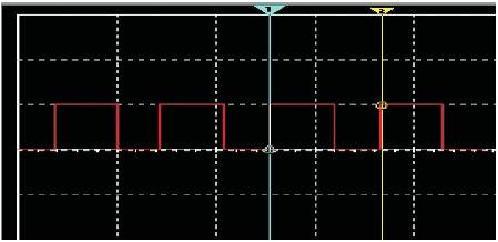
Figure 2. 60% Duty Cycle Signal
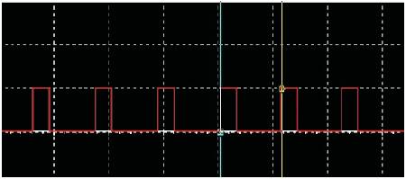
Figure 3. 25% Duty Cycle Signal
A thermistor is a temperature sensitive resistor. Thermistors typically achieve a higher precision within a limited temperature range, typically −90 °C to 130 °C. They can be Negative Temperature Coefficient thermistors where the resistance decreases with increase in temperature or Positive Temperature Coefficient thermistors whose temperature resistance relation is contrary to NTC thermistors.
Resistance thermometers, also called resistance temperature detectors (RTDs), are sensors used to measure temperature by correlating the resistance of the RTD element with temperature. Most RTD elements consist of a length of fine coiled wire wrapped around a ceramic or glass core. The element is usually quite fragile, so it is often placed inside a sheathed probe to protect it. The RTD element is made from a pure material, platinum, nickel or copper. The material has a predictable change in resistance as the temperature changes, and this predictable change is used to determine temperature.
The LM35 series are precision integrated-circuit temperature sensors, whose output voltage is linearly proportional to Celsius (Centigrade) temperature. The LM35 does not require any external calibration or trimming to provide typical accuracies of ±1⁄4˚Cat room temperature and ±3⁄4˚C over a full −55 to +150˚C temperature range.
By using a microcontroller say 8051, pulses with desired on and off times can be generated. A LM35 temperature sensor's output is fed to an Analog to Digital converter and this is interfaced with the microcontroller. The microcontroller is programmed to produce specific pulses for particular set of temperature. The output pulses then drive a fan, hence the speed of fan is controlled by temperature using microcontroller as PWM generating component.
An operational amplifier IC741 can be used to control a fan. The operational amplifier is used as a comparator and the output voltage from temperature sensor network is compared with the standard voltage calibrated with respect to a particular temperature. When the input voltage exceeds the reference voltage then the fan turns on. Hence the fan turns on only after a particular temperature is crossed. This temperature corresponds to reference voltage.
This paper proposes a prototype of cooling fan used in computers to prevent overheating. According to this method, the speed of a fan is controlled based on temperature by using the concept of Pulse Width Modulation. When there is an increase in temperature the duty cycle of the timer output signal also changes proportionately to increase the speed of the fan. Thus the increase in temperature is compensated by faster fan rotation and hence overheating is prevented. Figure 4 shows the system model. The fan circuit is powered using the USB Port of the PC. The voltage from a USB is 5V with maximum current rating of 0.5A. This is sufficient to drive the PWM Motor driver circuit [2].

Figure 4. System Model
A thermistor is used to sense a change in temperature. The thermistor is NTC (Negative Temperature Coefficient) i.e its resistance varies inversely with temperature.
This thermistor is connected in parallel with a potentiometer. Thus a variable resistance path is set for the charge and discharge cycle of the capacitor which helps in varying the width of pulses.
A 555 timer in a stable mode is used to generate the PWM signal. The output pin is connected to the temperature sensor component and a back to back diode configuration is used to provide charge and discharge path to the capacitor connected to trigger pin.
Initially when the circuit is powered, the trigger pin is in a logic low position since the capacitor C1 is not charged. The above condition initiates the oscillation cycle, making the output change to a logic high. A high output now forces the capacitor to charge via D2.On reaching a voltage level that's 2/3 of the supply, pin #6 which is the threshold of the IC triggers. The moment pin #6 triggers, pin #3 and pin #7 reverts to logic low.
With pin #3 at low, C1 yet again begins discharging via D1, and when the voltage across C1 falls below the level that's 1/3 of the supply voltage, pin #3 and pin #7 again become high, causing the cycle to follow and go on repeating.
C1 has two discretely set paths for the process of charging and discharging via the diodes D1, D2 and through the resistance arms set by the port respectively. It means the sum of the resistances encountered by C1 while charging and discharging remains the same no matter how the port is set, therefore the wavelength of the output pulse always remains the same.
Since the charge and discharge time periods are directly connected with the output duty cycle, it varies according to the adjustment of the port, giving form to the intended varying PWM pulses at the output. The average result of the mark/space ratio gives rise to the PWM output which in turn controls the speed of the motor.
The discharge pin of timer drives a IRFZ46N MOSFET transistor. The motor and hence fan is connected to the drain. The PWM pulses are fed to the gate of a MOSFET which reacts and controls the connected motor current in response to the setting of the port. The current level through the motor decides it speed and thus implements the controlling effect via the port and thermistor [4].
For a thermistor, resistance variation with temperature is given by
Rt= Ro (1 + α∆T)
Where Rt - Resistance at temperature T(Ω), Ro –Resistance at 0°C (Ω), α - Temperature coefficient of resistance (/°C), ∆T – Temperature change (°C).
Output frequency of PWM signals may be calculated as,
f = 1.44/(R1*C1)
Where f- frequency of signal generated (Hz), R1-equivalent resistance of potentiometer and thermistor (Ω), C1- Capacitance of capacitor connected to trigger pin(F).
In a normal external cooling fan the fan runs for the entire time its switched on. Assume a normal cooling fan and a temperature controlled PWM generated fan operating for a time period T.
In a normal fan the energy is consumed for the entire period T.
Energy = Power × Time (Joules)
Power = Voltage × Current (Watts)
Assume a normal cooling fan and a temperature controlled PWM generated fan operating for a time period T. In a normal fan the energy is consumed for the entire period T. Hence, Energy = Power × T (Joules) Figure 5 shows PWM Generation Circuit in MultiSim [3].
Now for the Temperature controlled fan using PWM the motor is powered for a fraction say 'a' of T. Hence the energy consumed is lesser for this fan than a normal fan. Figure 6. PWM Signal Waveform Simulated in Multisim Energy = Power × (aT) Joules
Hence the authors save the energy by using the pulsed switching and temperature sensing additions to a normal fan.
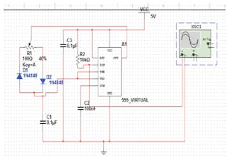
Figure 5. PWM Generation Circuit in MultiSim [3]

Figure 6. PWM Signal Waveform Simulated in Multisim
Thus, this report explains the working of a temperature controlled PC external cooling fan using pulse width modulation concept along with its working and simulated result. The necessary formulae for the user to set the pulse width or duty cycle of the signal according to convenience has also been provided. Proof for energy savings obtained by using the proposed model is provided. They can use the same concept in industry also. By using sensor, the authors can get the temperature information and the speed of the motor in the fan can be controlled from a remote place using mobile phone.