[1]
Advances Differential prot ecti on system is us e d t o protect most of the power transformers in power systems. The protection system is based on the differential currents/voltages of the primary an d secondary of the transformers under fault conditions and under normal operating conditions. The inrus currents or the magnetizing currents are generated in the transformer when it is switched on to the transmission system or the external fault in the system is cleared. The inrush currents other than the fault currents may activate the differential protection system if suitable blocking scheme is not incorporated in the protection system of the power transformer. Therefore, identification of inrush current and the fault currents is the key to improve the security of the differential protection scheme. This paper proposes the development of a new algorithm to improve the differential protection performance by using fuzzy logic and Clarke's transform. The result obtained concludes an effective method to differentiate the different internal faults with accuracy as well as shows an improvement in the time taken to detect faults.
Power transformers are a class of very expensive and important apparatus in electric power systems. The design of relays for power transformer protection has been a challenging problem for many years. Traditionally, a differential protection relay is always selected as a primary protection strategy for most power transformers. In a differential protection relay, differential currents can provide significant information about the feature of the current flowing through power transformer windings. Such information may include frequency contents, transient features, periodicity, and non-periodicity and frequency-time relations. There are many factors that should be considered when attempting to design a differential protection relay for power transformers, such as the magnetizing inrush current, over excitation and CT saturation.
Harmonic-restrained differential relay is based on the fact that the magnetizing inrush current has a large second harmonic component, and nowadays the above technique is widely applied [1] . But this technique must be modified because harmonics occur in a normal state of power system and the quantity of second frequency component in inrush state has been decreased because of the improvement in core steel. There are cases in which the presence of differential currents cannot make a clear distinction between fault and inrush [2] . New relaying technique with high reliability is required for flexibility in spite of change of condition in power system. The harmonics occurring during internal faults can cause the differential relay either not to operate or to operate with a time delay [3] . To avoid mal-operation due to inrush current, it is common practice to detect second harmonic component of current and block the differential protection of power transformer if it exceeds a certain value. Any internal fault with energization cannot be cleared quickly until the inrush fades out and the differential relay is unblocked. Most of these approaches are still liable to cause malfunction of the relay in the cases where the transformer is energized under complex connection conditions, in particular in the case where the inrush current has a low second harmonic component and the internal fault current has a high second harmonic component. This paper presents an efficient method based on Clarke transform with fuzzy sets for differential protection of power transformers. In the proposed technique, the input variables of the fuzzy-based relay are differential currents resulting from Clarke's transform. The fuzzy system is designed to distinguish internal faults from other operating conditions of the power transformer, even for faults near the neutral. To test the proposed algorithm, computing simulations were performed using MATLAB software. A complex power system was implemented, where its dynamic behavior could be observed. The simulation includes: a synchronous generator with speed and voltage control, transmission lines using frequency-dependent parameters, and six power transformers. Extreme operational situations were used in order to observe the behavior of the Proposed technique, to compare it to the performance of commercial relays and, finally, to validate the obtained results.
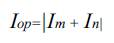
Large transformers are generally protected by percentage current differential relays with restraining algorithms based on second and sometimes fifth harmonics [3] , [4]. The percentage current differential protection has been recognized as the most principal theory of transformer protection and has had a proven record of reliable operation for many years. A percentage differential function is applied to the fundamental component of the currents to decide whether an internal fault has occurred. It converts the primary and secondary currents to a common base and compares the operating current with a restraining current. The difference between the operating and restraining currents is small for normal operating condition and external faults, while it becomes significant during the internal fault. The operating current of percentage current differential protection can be obtained by taking into account the primary and secondary current of the transformer by
Where Im and In are the primary and secondary Current respectively and Iop is proportional to the fault current for internal faults and approaches zero for other operating (ideal) conditions.
Different alternatives have been applied to obtain the restraining current.
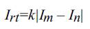
Where k is a compensation factor, commonly taken as 1 or 0.5. The relay sends a trip signal to the Circuit Breaker (CB) when the differential current is greater than a percentage of the restraint current. As mentioned before, certain phenomena can cause a substantial differential current to flow when there is no fault, and then this false differential current is generally sufficient to cause tripping. However, in these situations, the differential protection should not disconnect the transformer because an internal fault is not present.
Magnetizing currents appear during transformer energization due to ts core magnetization and saturation. In modern transformers, large inrush currents can be reached. In transformer energization, as the Secondary winding is opened; the differential current can reach sufficiently high values, causing a false relay operation. It must be emphasized that inrush currents can take place, even when the transformer is connected to a load. Some other phenomena that cause false differential currents are magnetizing inrush currents during an external fault removal, transformer over excitation, sympathetic interaction, as well as CT saturation. [8]
The algorithm was implemented in the C++ programming language and it is illustrated in Figure 1. To obtain the primary and secondary current signals from the transformer simulation of the system is done using MATLAB software. After acquiring the data, the signals are processed using Clarke's transform and the differential currents are calculated. These currents are the input of the fuzzy system. If the output of the fuzzy system is greater than the threshold value of 0.5, the control counter (ctr_k) is increased by 1.When this counter has exceeded the threshold 3,
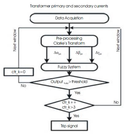
Figure 1. Algorithm for C++ Programming
The relay sends a trip signal to the CB. It is important to emphasize that the proposed fuzzy system computes each differential component independently. [7]
The following section will describe each block individually
An electrical power system was modeled using MATLAB 2010 software to obtain the operational conditions and fault situations needed to test the algorithm developed. Three operations states are taken into account. Fault due to energization, inrush current and no fault operation.
The three phase primary and secondary currents were stored in workstations using Simulink for input to the Clarkes transform method. Iabc1 is taken as the primary phase current of the transformer and Iabc is taken as the secondary phase current of the transformer.
After acquiring the data, a preprocessing stage was executed, obtaining the uncoupled signals for the fuzzy system. This was obtained by applying Clarke's Transform to the three-phase currents in the secondary winding current of the CT in both transformer ends, as represented in the following equation (1):
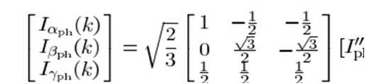
It is important to emphasize that Clarke's transform could be applied to both instantaneous values as well as the phasors.
The main idea of using Clarke's Transform is carried out in a pattern-recognition process to discriminate certain conditions of transformers, such as internal faults, over excitation, sympathetic inrush, and energization. The proposed method uses the differential α, β, γ components of the current, such as
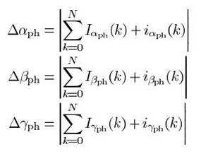
Where Iα,Iβ,Iγ, iα, iβ and iγ are the α-γ-β components of the primary and secondary currents from a transformer respectively and N is the number of signal samples in the observation window.
It should be mentioned that the computed values of the differential components of the currents are approximately zero in the case of a normal operation, while the range of each differential current value fluctuates according to the specific situation. Therefore, the various phenomena of the transformer could be discriminated.
The fuzzy system is used to deal with the input imprecisions without data loss during processing and to determine the fault condition more accurately than conventional differential protection methods [5].
Some of the steps of the fuzzy logic are:
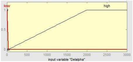
Figure 2. Input Variable “Delalpha”
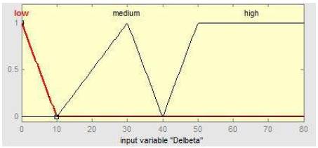
Figure 3. Input Variable “Delbeta”
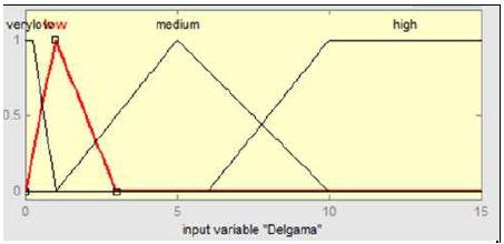
Figure 4. Input Variable “Delgama”
For fuzzification of a defined input variable from (3), a range is set between 0 and 100 and the membership values range from 0 to 1. The other input variables from (3) and (4) are in the range from 0 to 50. The output variable is shown in Figure (5) ranging from 0 to 1 for two membership functions that determine block or trip signals.
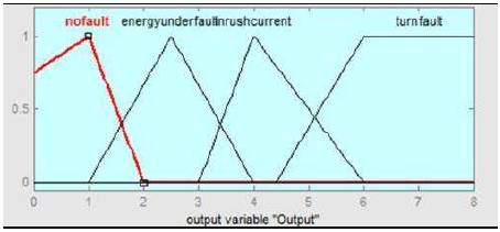
Figure 5. Two Membership functions

Table 1. Fuzzy Rules
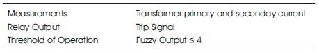
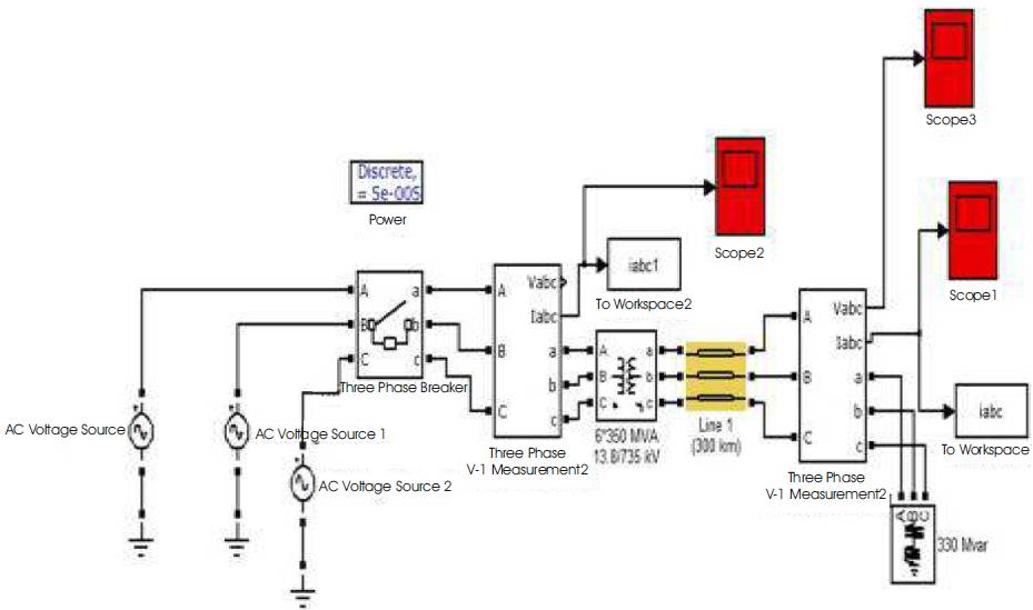
Table 2. Specification of Proposed Relay
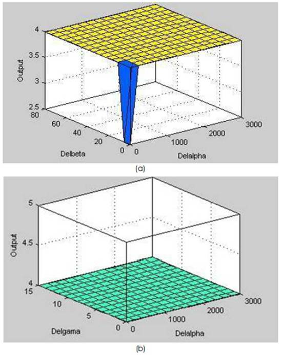
Figure 6. Fuzzy Rules: Surface view of (a) Δα vs Δβ and (b) Δα vs Δγ.
The electrical system was simulated using MATLAB software. Figure 7 shows the representation of the simulated power system taking into account load switching and permanent faults in order to evaluate the differential technique proposed in this paper.
The simulated system consists of a 13.8 kV and a 3000-MVA (60 Hz) synchronous generator, 13.8:735-kV and 350-MVA three-phase power transformers, transmission lines between 50 and 100 km in length, and loads between 5 and 25 MVA with a 0.92 inductive power factor. Power transformers have a delta connection in the low-voltagewinding and a wye connection in the high-voltage winding.
The power transformers were modeled using MATLAB software. [9]
Concerning the better performance of the proposed technique, it is worth mentioning that because the estimation of the harmonic components was not used, this approach works with time windows much lower than one cycle of the fundamental frequency, considerably decreasing the trip time of the relay based on this theory. On the other hand, considering the traditional approach embedded in the commercial relays, in order to obtain a good estimation of the analyzed signal, windows of one cycle of the fundamental frequency are required. This paper presented a new method for digital protection of power transformers using Clarke's transform and fuzzy logic. This technique has shown some advantages regarding the traditional ones.
The implementation of the proposed technique uses the current signals from power transformers and its components to discriminate faults from other operating conditions. [10]
The simulations used to test the proposed algorithm were obtained by using the MATLAB software. Clarke's transform and the fuzzy logic applied to the digital protection were fast and reliable. Some points should be observed as follows.