
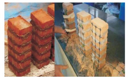
Figure 1. Prisms of Horizontal and Vertical Reinforcement
An earthquake is a natural disaster that occurs on earth, due to which the loss of life and property is at a greatest extent. One of its direct effects is on masonry structures. The masonry being brittle in nature tends to fail easily under lateral loads. In this paper, an attempt is made to increase the ductility of masonry by using geogrids as reinforcement. Geogrids are the high tensile geosynthetics which have high flexibility and durability. The stress strain behaviour is one of the most important characteristics of the material, which focuses on the behaviour of material under loading. A comparison study is made with and without geogrid reinforcement. The modulus of elasticity is found by constructing stack bond prisms using stabilized mud blocks.
A majority of the dwelling units in India is made of single and two storeyed masonry. The masonry used ranges from the unburnt brick masonry used in villages to concrete blocks, bricks, and stone masonry in semi urban and urban areas. It is well known that these low rise masonry buildings suffer a great deal of damage even during low magnitude earthquakes.
Masonry structures are built and used in almost all the places on earth. These structures are very good with vertical loads and hence used worldwide, but for lateral loads the masonry structure is weak which undergoes flexural and shear failure. The majority of the masonry structures are unreinforced and fail due to brittle failure. An attempt is made to avoid the brittle failure and improve the ductility of the structure using geogrid as a reinforcement material in the joint between the bricks. The geogrids are cut to the size of scaled bricks and attached between the bricks for testing of Young's modulus so that the stress strain behavior can be understood thoroughly. Comparison is made between the different combinations of reinforcement and without reinforcement. The characteristics of the masonry structure should be very well known to understand the behaviour of structure during earthquake and hence the stress strain behaviour and the shear strength of masonry structure reinforced with geogrids are focused.
Waziri and Lawan (2013)have prepared stabilized mud blocks by varying the percentage of cement from 0% to 7.5%. The mud blocks are prepared with CINVA-Ram machine that is the hand operated press machine. The blocks are cured for 28 days and tested using the universal testing machine. The blocks are tested for different ages from 7 days to 28 days to know the rate of strength gain. The strength of the blocks increased with the increase in cement content from 0% to 7.5% at an average of 0.35 2 N/mm and the highest compressive strength was obtained with 7.5% cement content for curing of 28 days. The maximum strength got from these is within the minimum limits of strength requirement, which is recommended for low rise building construction.
Reddy, Lla, and Rao (2007)have studied focuses on the shear bond strength of the soil cement blocks and also the changes in compressive strength due to change in shear strength. The blocks are prepared with 8% of cement content by weight. The compressive strength of the soil cement block masonry is tested by making a five brick stack bound prism. For measuring the longitudinal strain, a 200 mm demec gauge is used and the mortar thickness of 12 mm is maintained. The results of these show that the bond strength is independent of the stress strain characteristics and bond strength can be improved by the surface alterations.
Tennant et al. (2016) have studied the flexural behavior of the cement stabilized mud blocks, which is a very important factor in the observation of structural behavior. For stabilization of mud blocks, 7% of cement is used by weight. To determine the compressive strength of the masonry, five block prisms are constructed. The mortar joint of 10 mm is adopted for the prisms and are tested in displacement control machine at the rate of 0.61 mm/min.
Riza et al. (2011) have studied the comparison of strength between the normal burnt brick and the compressed stabilized earth block. The cement as stabilizer is added 4 to 10% by weight and above 10% leads to uneconomic to produce compressed stabilized earth block and also it is found that above 10% of cement affects the strength in a negative way. It is concluded that the compressed stabilized earth block are ecofriendly and comparable in durability, strength, and thermal conductivity.
Walker (1995) had studied the strength and durability of cement stabilized mud blocks. Ordinary portland cement has been used for the stabilization of blocks. Cement ratios of 1:10, 1:15, 1:20 (cement soil by dry volume) were used. Also the cement content above 10% becomes uneconomical and blocks containing cement less than 5% are too friable to easy handling.
After reviewing the literatures on reinforced masonry structures it has been observed that geogrids are used as reinforcement in many retaining walls, but fewer studies on implementation of geogrids reinforcement in the masonry structures. This paper mainly deals with the behavior of geogrid reinforced masonry prisms.
After testing the materials for basic properties, compressed stabilized mud blocks were prepared by using 8% cement as stabilizer (Kaushik et al., 2007). The blocks were scaled to a size of 4” x 3” x 2” (101 mm x 76 mm x 50 mm) and are cured for 28 days.
To determine Young's modulus stack bond prism are constructed which comprises of brick and mortar whose height to width ratio is within the prescribed IS limits. The mortar used in the ratio 1:6 (cement:sand) and the sand used is natural river sand (Reddy & Gupta, 2006). The thickness of the mortar is maintained at 10 mm for every prism (Tennant et al., 2016; Tensing, 2013). The height to width ratio is maintained to 3.46 which should be above 2 and below 5 as prescribed by the IS masonry codes IS: 3495 (1992). The geogrids for horizontal reinforcement is cut to desired size of brick and are attached to the brick surface by nailing the geogrid to brick. For vertical reinforcement, the geogrid is attached to the larger face by using binding wire as shown in Figure 1. The geogrids were reinforced with three different combinations and the results are compared with unreinforced prisms. The combinations are unreinforced [A], Reinforcement in each layer [B], Reinforcement in alternate layers [C], and Vertical reinforcement. For each combination of reinforcement, six prisms are constructed and a total of 24 prisms are constructed and cured for 28 days. The load is applied with universal testing machine and the deformation is recorded by using demec gauge as shown in Figure 3.
Figure 1. Prisms of Horizontal and Vertical Reinforcement


Figure 3. Demec Gauge
For testing of shear strength, shear specimens are constructed with geogrid reinforcement and without geogrid reinforcement as shown in Figure 2. The bricks are arranged such that the load can be applied to the middle brick and the shear to be experienced both sides of the brick. The distance of the centre brick is equally maintained for all the specimens (Narayanan & Sirajuddin, 2013). Same procedure is used for the constructing six specimens without geogrid reinforcement and six specimens with geogrid reinforcement are as shown in Figure 4.
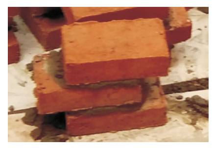

Figure 2. Specimen for Shear Strength Test

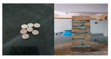
Figure 4. Pins Attached to Prisms at a Gauge Length of 150 mm
The basic materials used are soil, cement, and geogrids. The soil is selected based on the clay content and sieved through 4.75 mm sieve, the cement used is 53 grade. The geogrids used are of biaxial type, made up of polypropylene material with aperture size of 40 mm X 40 mm and having the thickness of 2 mm with tensile strength of 0.410 MPa (test results).
Materials used are the tested for basic properties according to IS standards. Following table shows basic properties of the Soil and cement are as shown in Table 1.

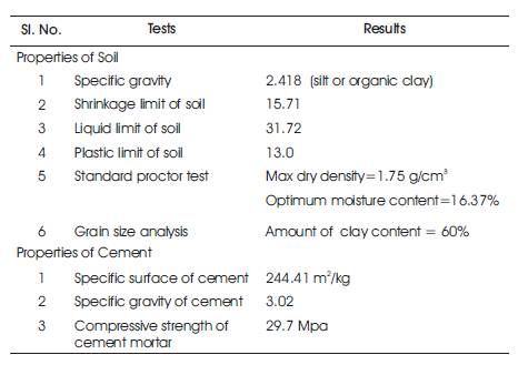
Table 1. Properties of Materials
For the test for prism, different combinations are tested and calculation of stress and strain is done from which the normalized graph is plotted and the polynomial curve is fitted to the obtained points and the equation of the polynomial gives the Young's modulus for that particular combination of prisms.
The Young's modulus and compressive strength are found for all four combinations and is tabulated and the comprehensive results are as given in Table 2.

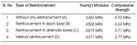
Table 2. Comprehensive Results of Young's Modulus and Compressive Strength for all the Combinations
The shear specimens after curing are dried and tested under California Bearing Ratio (CBR) testing machine. The specimen is loaded on the top using the metal plate and the rate of loading was 0.5 mm/min. The load is applied till failure and the load applied is recorded from which shear stress is calculated by dividing load by two times the surface area. The shear stress for two combinations is shown in Table 3 and Figure 5.

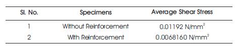
Table 3. Table Showing Shear Stress Calculations

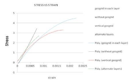
Figure 5. Graph showing the Polynomial Line of Stress Strain Relationship of all Four Combinations
The use of geogrids as reinforcement in masonry prisms increases the Young's modulus. The Young's modulus of prisms reinforced with geogrids at alternate layers is approximately near to the prisms reinforced with geogrids in all layers. The reinforced prisms are capable of taking more strain at the time of failure when compared to unreinforced prisms. Masonry prisms being brittle in nature upon usage of geogrid reinforcement helps to improve the ductile behavior of the masonry prisms thereby withstands the sudden variations of loads thus improving the stability of the masonry prisms.