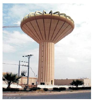
Figure 1. Reinforced Concrete Pure Conical Tank in Saudi Arabia in Al-Riyadh Newspaper (Al-Riyadh Newspaper, 2009)
Pure conical elevated water tanks are widely used as water reservoirs in various locations around the world. Current Indian codes of practice do not provide any provisions or guidelines for the analysis and design of reinforced concrete pure conical elevated water tanks under hydrostatic loading. Available code provisions are limited only for the design of cylindrical and rectangular tanks. In this paper, a Finite Element Model (FEM) of pure conical elevated water tank is made by using a structural analysis and design computer program, i.e. STAAD.Pro. The current study focus on the behavior of pure conical elevated water tanks under varying tank inclination (θ) for a constant volume of 500 cubic meter. The aim of this research paper is to find out the optimum angle of inclination (θ) for the conical tank by performing Dynamic analysis, i.e. using response spectrum method. The inclination (θ) of the conical tank is increased at a rate of 5o and varies from 15o to 80o are considered in the analysis. The entire tanks are model for the seismic zone-V as per IS-1893- 2002. The Response of each conical tank with respect to others will be checked for Base Shear, Principal stresses, Hoop Stresses, Meridional Stresses, Bending Moment in plates, for conical portion and Shaft portion, Bending Moments in ring Beam, and Lateral displacement. The behavior of each conical tank with respect to others is shown with the help of graphs for Empty tank and Full tank condition.
Elevated water tanks are extensively used for storing various liquids in municipalities and industries. The commonly used shapes for these tanks are rectangular and circular. Now-adays truncated conical shape type tanks are commonly used for storing liquids in various locations around the world. The truncated conical water tank is divided into two types “combine conical tank” and “pure conical tank”. A conical vessel with a top overlying cylindrical part is referred as a “combine conical tank” whereas a conical vessel without top overlying.
Cylindrical part is referred as a “pure conical tank” as shown in Figure 1. The top conical part is made of either by Steel or Reinforced concrete while the shaft is usually made of Reinforced concrete. The current study focus on the seismic behavior of pure conical elevated water tanks under varying tank inclination (θ) for a constant volume of 500 m3. Azabi and ELDamatty (2014) have analyzed a set of reinforced concrete elevated pure conical tanks using a finite element method based on a three-dimensional consistent shell element developed by koziey and Mirza [7-8], Azabi then assessed the accuracy of a simplified approach for the analysis and design of reinforced concrete conical tanks. This approach is based on Portland Cement Association (PCA) and combine with equivalent cylindrical approach by American Water Works Association (AWWA). The comparison in carried out between the internal force obtained from their numerical models with those resulting from the Portland Cement Association (PCA) design aids, a significant difference was obtain between the internal force obtained from their numerical models with those resulting from the Portland Cement Association (PCA) design aids.
Figure 1. Reinforced Concrete Pure Conical Tank in Saudi Arabia in Al-Riyadh Newspaper (Al-Riyadh Newspaper, 2009)
ELAnsary and ELDamatty (2013) have carried out a Nonlinear finite element analysis on a reinforced concrete conical tank in order to understand their behavior under hydrostatic pressure, the model of the conical tank is made of by using shell elements. The Finite element model made by Azabi and ELDamatty (2014) was extended by ELAnsary et al., (2015) to account the shrinkage and nonlinear behavior of concrete under hydrostatic pressure. Total twelve reinforced concrete finite element model were made with a wide range of practical dimensions. The results of their study were concluded for maximum deflection of tanks wall, Maximum hoop stress, and Maximum meridional stress are considered. ELAnsary et al., (2016) developed a nonlinear Finite Element Model (FEM) based on shell element, used to analyzed a reinforced concrete conical tanks subjected to hydrostatic pressure. They also replaced the conical vessels with an equivalent cylinder. The result of the equivalent cylinder are compared with the finite element model, finite element model are used to developed the Graphs for adequate thickness and straining action that developed in a liquid filled reinforced concrete conical tank. ELAnsary and ELDamatty (2016) present the first comprehensive study conducted on liquid filled composite conical tank, a finite element model of composite conical tanks were made considering both geometric and material nonlinearity. The behavior of the composite tank is observed for deflection, stresses and internal forces in the concrete as well as steel walls. ELDamatty et al., (1997) carried out a study to evaluate the stability of imperfect steel conical tanks under hydrostatic loading. Conical steel tank were modeled by using Finite element shell that includes both geometric nonlinearities and material nonlinearities. The result of their study showed that liquid filled conical shells are quite sensitive to geometric imperfections. This simplified approach was again extended by ELDamatty et al., (1998) to investigate the effect of different imperfection shapes on the inelastic stability of liquid filled conical tank. The result of their study showed that inelastic buckling of steel conical tanks was most sensitive to axisymmetric imperfection. ELDamatty et al., (2001) found that the use of welded stiffeners at the bottom portion of steel conical tank can significantly improve the buckling capacity of conical tanks. This simplified approach of stiffener is again considered by ELDamatty and Marroquin (2002) for existing tanks and for the design of newly stiffened ones. The design procedure is then described graphically. Later on ELDamatty et al., (2005) perform an experimental study conducted on a liquid filled combined conical tank. The results of these experiments are used to validate the assumption of previously developed analytical model for the free sloshing motion, and similar experiments are again conducted by ELDamatty et al., (2005) for knowing the dynamic characteristic of conical vessel and evaluation of wind forces and seismic forces. ELDamatty and Sweedan (2006) have developed a simplified mechanical analog which can be used to estimate the forces associated with horizontal ground excitation. The proposed mechanical analog consider both the components i.e. Impulsive and convective component of hydrodynamic pressure. Hafeez et al., (2010) have carried out a study on combined imperfect conical tanks subjected to hydrostatic loading, finally conclusion are drawn between buckling capacities of combined tanks and equivalent pure conical tanks. Hafeez et al., (2011) carried out an analysis on stability of conical tank against the combined effect of wind loading and hydrostatic pressure on the conical tank. Housner (1963) proposed a theory on two mass models for elevated water tanks. This theory is implemented in various codes around the world. He has divided the total mass of liquid in the tanks into two parts, i.e. impulsive part and Convective part. Convective part is that part of liquid in the upper region of tank which creates sloshing movement whereas Impulsive part is that part of liquid in the lower region which is rigidly attached with the tank wall. IS-1893-2002 Part-II provides the guideline for Earthquake resistant design of liquid retaining structure. The analysis and design of liquid retaining structure is carried out by using Housner's theory, i.e. Two degree of freedom considering Impulsive liquid mass and Convective liquid mass. IS-3370-2009 (Part-I to IV) provides the guideline for design of concrete structure storing liquid. IS-11682-1985 provides the guideline for design of RCC staging for overhead water tanks. Jolie et al., (2013) carried out a study for assessment of current design procedures for conical tank by using previously established equivalent model under horizontal excitation. The results of their study reveal that approximate approach is not adequate for designing conical tanks to resist the seismic forces. Using the same equivalent mechanical model, Jolie et al., (2014) perform the seismic analysis of pure conical tanks under vertical excitation to estimate the normal forces developed in the tank walls. In addition to this a three dimensional finite element model is developed to predict the maximum membrane and meridional stresses developed due to both hydrostatic and hydrodynamic pressure distribution. Musa and ELDamatty (2016) perform a static pushover analysis on a finite element model of steel conical tank subjected to hydrodynamic pressure associated with vertical ground excitations. They have also considered the effect of geometric and material nonlinearities and finally the graphs are developed to estimate the capacity of steel conical tanks to resist the vertical ground excitation (Sweedan and ELDamatty, 2002). An experimental and analytical study for the dynamic characteristics of conical shells was carried out. The results of their study are very useful in assessing the dynamic response of conical tanks when it is subjected to wind load and seismic forces. Sweedan and ELDamatty (2005) carried out a study on Equivalent models under vertical ground excitation. The current study is conducted to establish a simple design procedure that can be used to estimate the seismic forces acting on conical tank subjected to vertical ground excitation. Sweedan and ELDamatty (2009) have carried out a study which covers the design approach for combined steel conical tank and to provide safety against hydrostatic loading and buckling.
A reinforced concrete pure conical elevated water tanks are considered for a constant volume of 500 m3 and a set of total 14 tanks with different tank Inclination (θ) varying from 15o to 80o is chosen to be studied in this research. All the tanks were a model for Seismic Zone-V as per IS-1893-2002. The analysis of this tanks are carried out by using a structural analysis and design computer program, i.e. STAAD.Pro, the shaft and conical portion of the tank are modeled by using four node Iso-parametric plate element whereas the central column for staircase and ring beam are modeled as beam element with six degree of freedom at each node. The details of geometric properties, design parameters, and sectional properties of pure conical elevated water tanks are given in Table 1, Table 2, and Table 3, respectively.
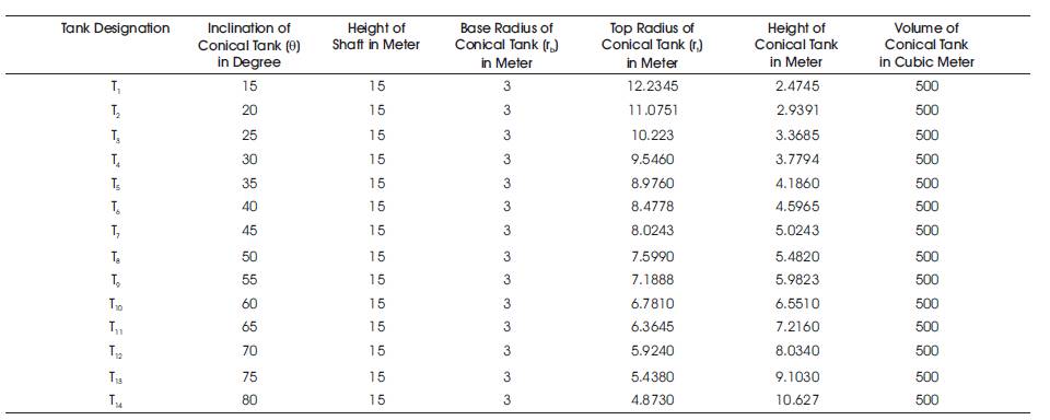
Table 1. Geometric Properties of Pure Conical Elevated Water Tank
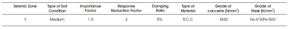
Table 2. Design Parameters for Pure Conical Elevated Water Tank
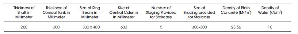
Table 3. Sectional Properties of Pure Conical Elevated Water Tank
Figure 2 show the finite element model made by using STAAD.Pro and Figure 3 shows the geometric properties of conical tank. Figure 4 and Figure 5 show the plan view through shaft and conical portion, respectively. Table 4 shows the maximum value of mass and base shear.
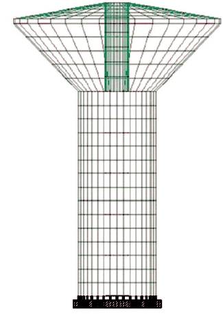
Figure 2. Finite Element Model Made by using STAAD.Pro Software
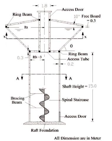
Figure 3. Geometric Properties of Pure Conical Elevated Water Tank
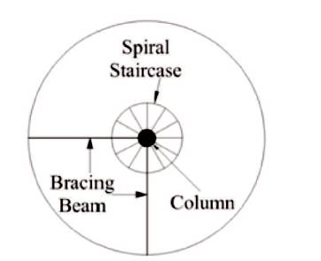
Figure 4. Plan View Through Section 'AA' for Shaft Portion
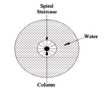
Figure 5. Plan View Through Section 'XX' for Conical Portion
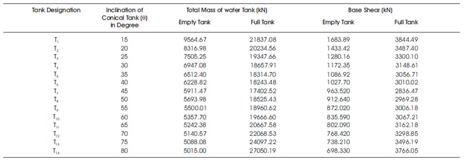
Table 4. Maximum Values of Mass and Base Shear for Empty and Full Tank Condition

Figure 6. Mass of Conical Water Tank for Empty Tank Condition

Figure 7. Mass of Conical Water Tank for Full Tank Condition
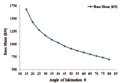
Figure 8. Value of Maximum Base Shear for Empty Tank Condition
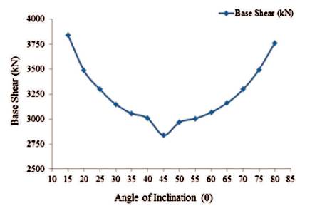
Figure 9. Value of Maximum Base Shear for Full Tank Condition
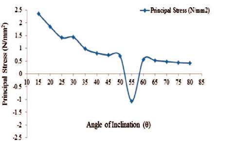
Figure 10. Maximum Values of Principal for Conical Portion (Empty Tank)
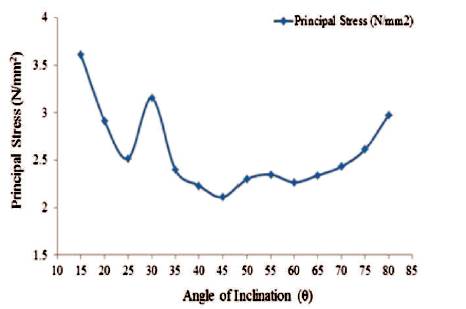
Figure 11. Maximum Values of Principal Stress for Conical Portion (Full Tank)
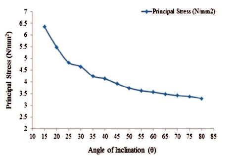
Figure12. Maximum Values of Principal Stress for Shaft Portion (Empty Tank)
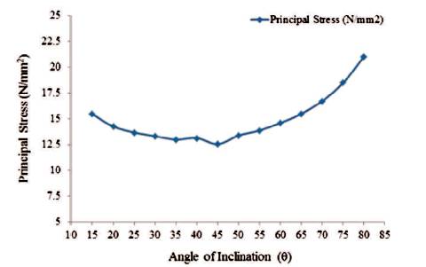
Figure 13. Maximum Values of Principal Stress for Shaft Portion (Full Tank)
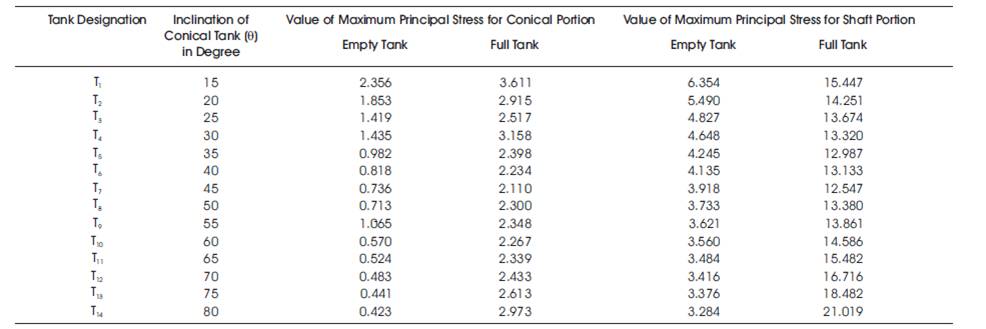
Table 5. Maximum Values of Principal Stress for Conical Portion and Shaft Portion
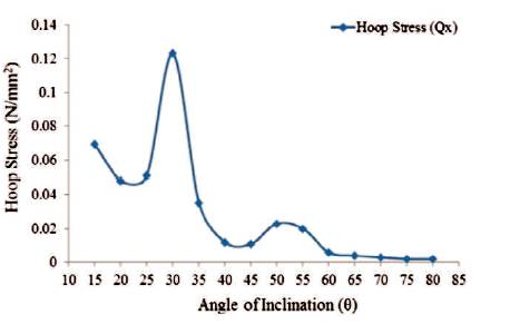
Figure14. Maximum Values of Hoop Stress for Conical Portion (Empty Tank)
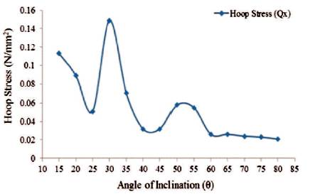
Figure15. Maximum Values of Hoop Stress for Conical Portion (Full Tank)
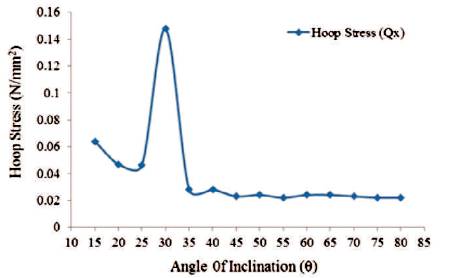
Figure16. Maximum Values of Hoop Stress for Shaft Portion (Empty Tank)
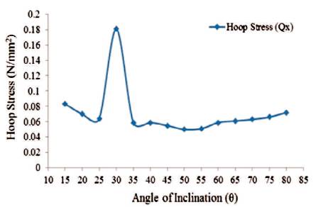
Figure17. Maximum Values of Hoop Stress for Shaft Portion (Full Tank)
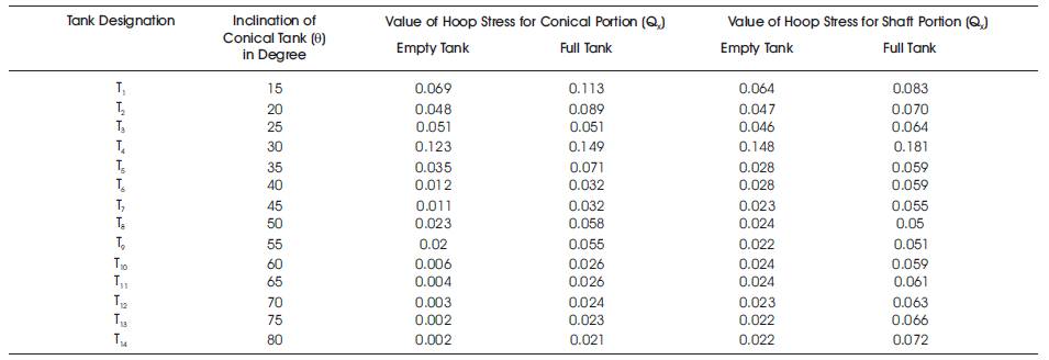
Table 6. Maximum Values of Hoop Stress for Conical Portion and Shaft Portion
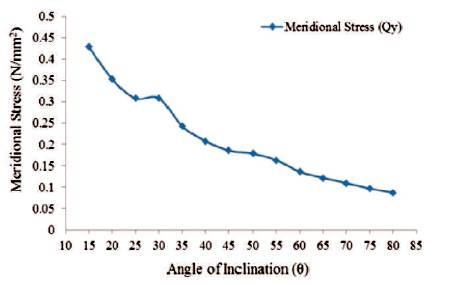
Figure 18. Maximum Values of Meridional Stress for Conical Portion (Empty Tank)
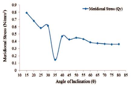
Figure 19. Maximum Values of Meridional Stress for Conical Portion (Full Tank)
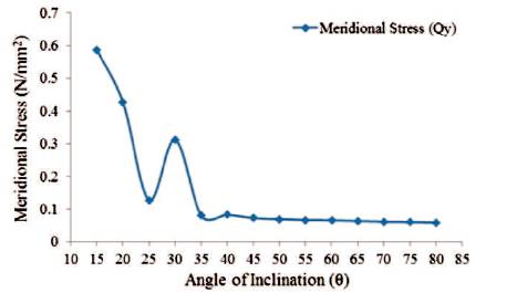
Figure 20. Maximum Values of Meridional Stress for Shaft Portion (Empty Tank)
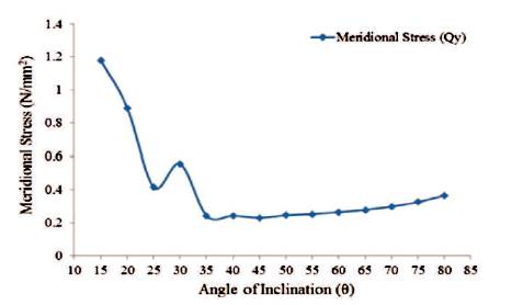
Figure 21. Maximum Values of Meridional Stress for Shaft Portion (Full Tank)
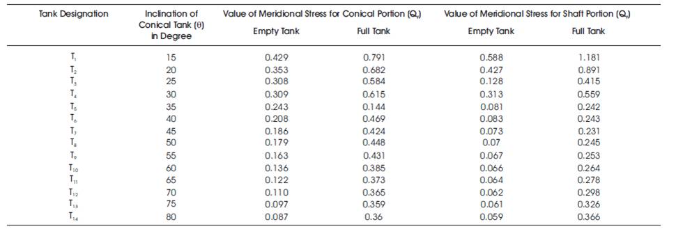
Table 7. Maximum Values of Meridional Stress for Conical Portion and Shaft Portion
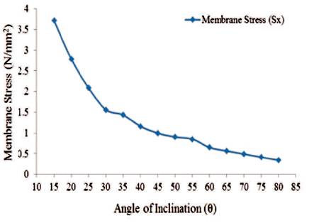
Figure 22. Maximum Values of Membrane Stress in 'X'-Direction for Conical Portion (Empty Tank)
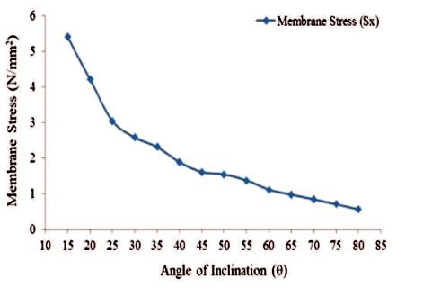
Figure 23. Maximum Values of Membrane Stress in 'X'-Direction for Conical Portion (Full Tank)
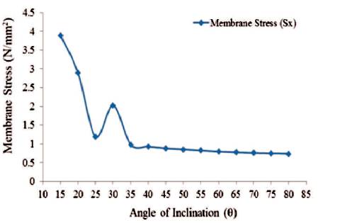
Figure 24. Maximum Values of Membrane Stress in 'X'-Direction for Shaft Portion (Empty Tank)
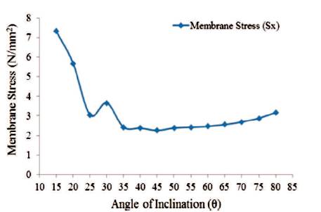
Figure 25. Maximum Values of Membrane Stress in X'-Direction for Shaft Portion (Full Tank)
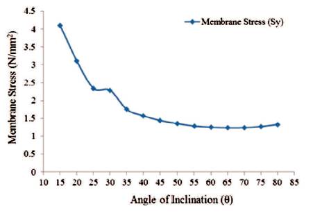
Figure 26. Maximum Values of Membrane Stress in 'Y'-Direction for Conical Portion (Empty Tank)
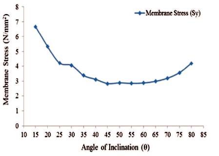
Figure 27. Maximum Values of Membrane Stress in 'Y'-Direction for Conical Portion (Full Tank
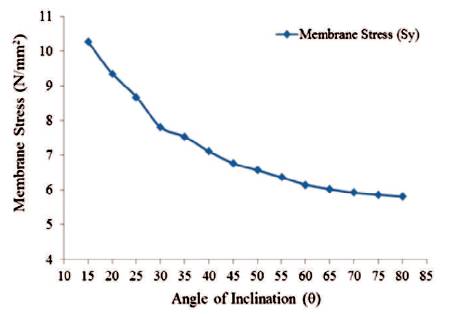
Figure 28. Maximum Values of Membrane Stress in 'Y'-Direction for Shaft Portion (Empty Tank)
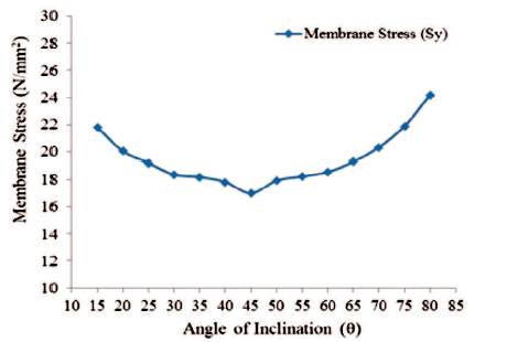
Figure 29. Maximum Values of Membrane Stress in 'Y'-Direction for Shaft Portion (Full Tank)
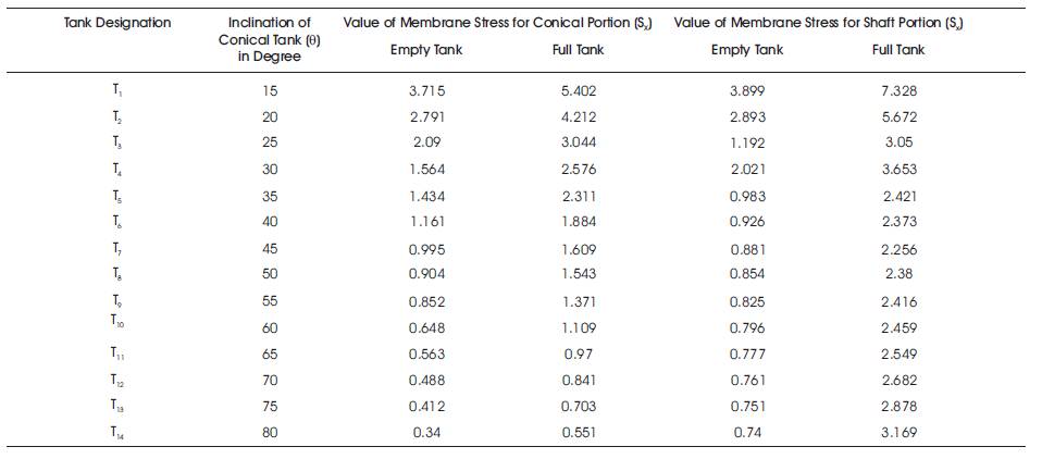
Table 8. Maximum Values of Membrane Stress in 'X' Direction for Conical Portion and Shaft Portion
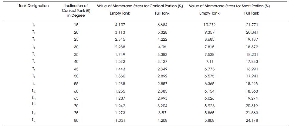
Table 9. Maximum Values of Membrane Stress in 'Y' Direction for Conical Portion and Shaft Portion
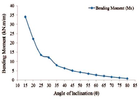
Figure 30. Maximum Values of Bending Moment in 'X'-Direction for Conical Portion (Empty Tank)
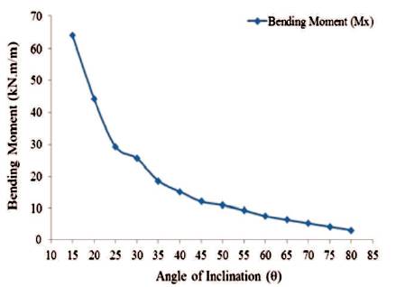
Figure 31. Maximum Values of Bending Moment in 'X'-Direction for Conical Portion (Full Tank)
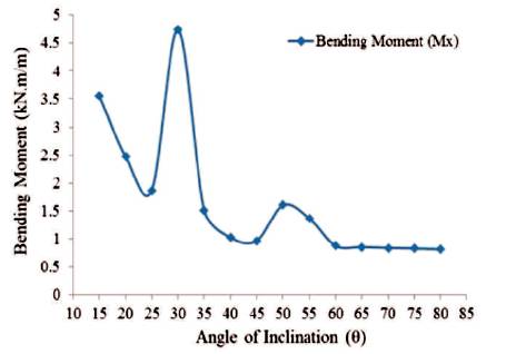
Figure 32. Maximum Values of Bending Moment in 'X'-Direction for Shaft Portion (Empty Tank)

Figure 33. Maximum Values of Membrane Stress in 'X'-Direction for Shaft Portion (Full Tank)
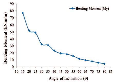
Figure 34. Maximum Values of Bending Moment in 'Y'-Direction for Conical Portion (Empty Tank)
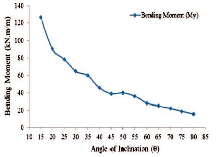
Figure 35. Maximum Values of Bending Moment in 'Y'-Direction for Conical Portion (Full Tank)
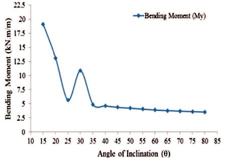
Figure 36. Maximum Values of Bending Moment in 'Y'-Direction for Shaft Portion (Empty Tank)
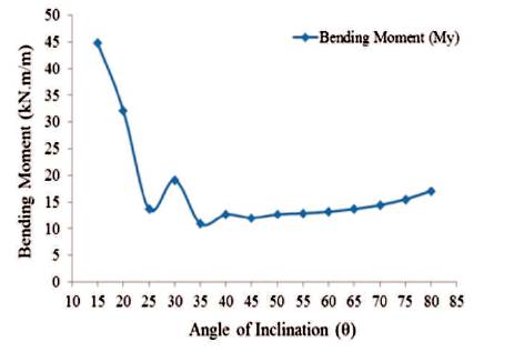
Figure 37. Maximum Values of Membrane Stress in 'Y'-Direction for Shaft Portion (Full Tank)
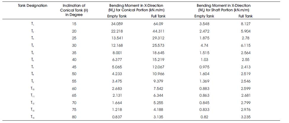
Table 10. Maximum Values of Plate Bending Moment in X-Direction (Mx ) per Meter Length
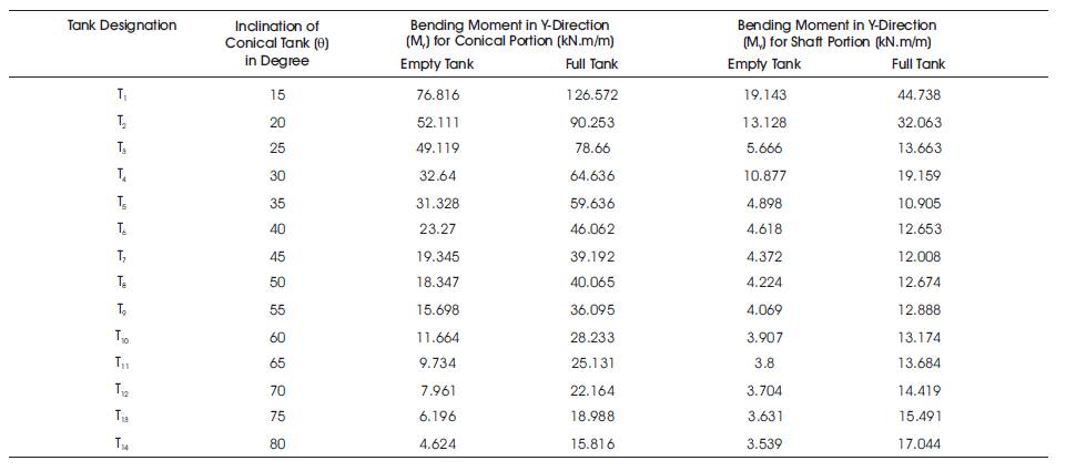
Table 11. Maximum Values of Plate Bending Moment in Y-Direction (M y) per Meter Length
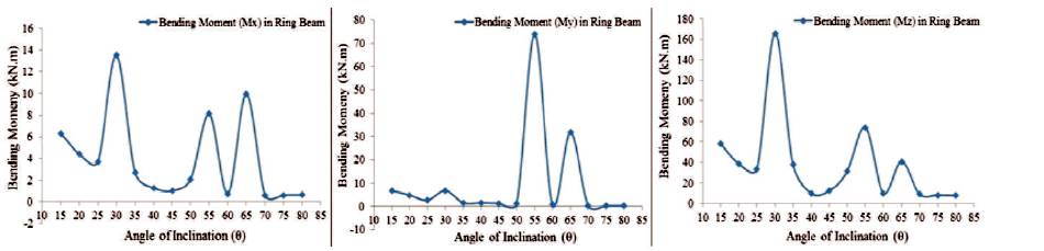
Figure 38. Maximum Values of Bending Moment (Mx ) (My ), and (Mz ) in Ring Beam for Empty Tank Condition
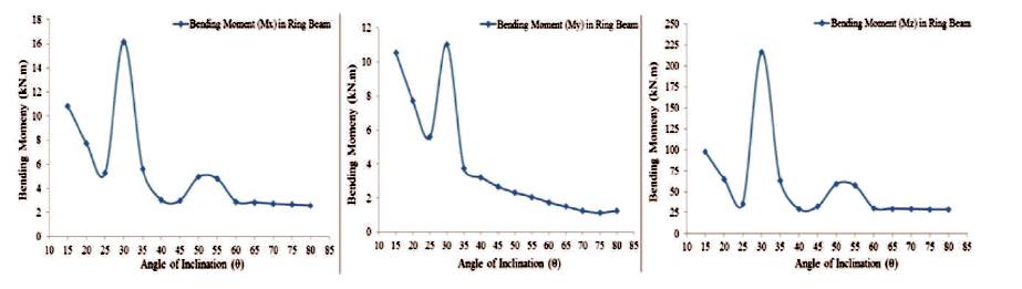
Figure 39. Maximum Values of Bending Moment (Mx ) (My ), and (Mz ) in Ring Beam for Full Tank Condition
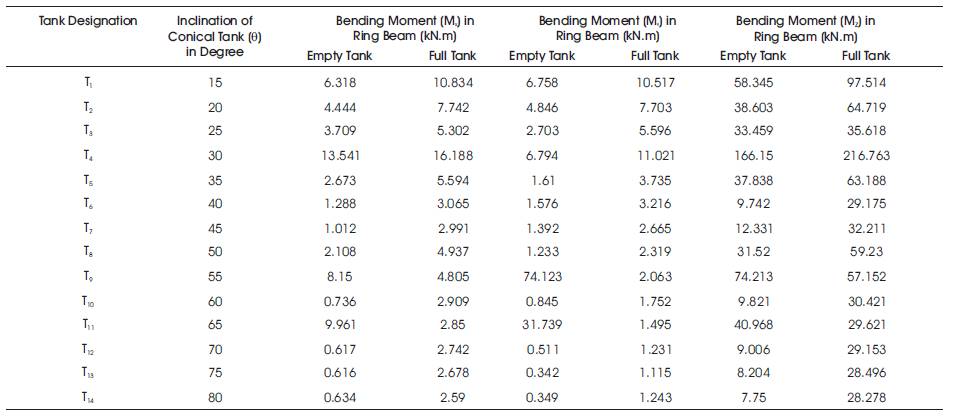
Table 12. Maximum Values of Bending Moment in Ring Beam
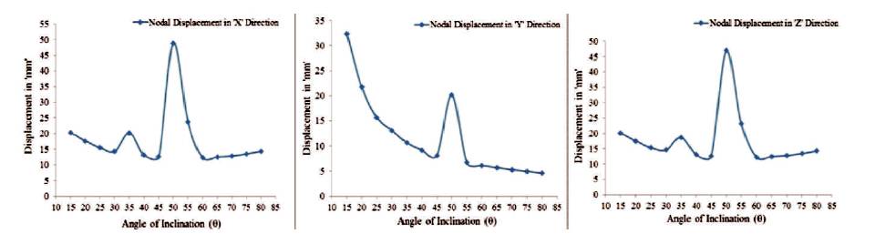
Figure 40. Maximum Values of Nodal Displacement (δx), (δy), and (δz) for Empty Tank Condition
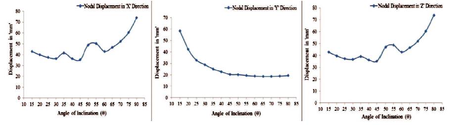
Figure.41 Maximum Values of Nodal Displacement (δx), (δy), and (δz) for Full Tank Condition
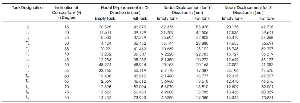
Table 13. Maximum Values of Nodal Displacement
From the above discussion it is concluded that,