Analysis of a Northlight Folded Plate – Whitney Method
G. Alekhya * V. Lakshmi **
* Assistant Professor, Department of Civil
Engineering, ACE Engineering College, Telangana, India.
** Associate Professor, Department of Civil
Engineering, University College of Engineering, Jawaharlal Nehru
Technological University, Andhra Pradesh, India.
Abstract
Modernization and urbanization world-wide have led to the increase in
many high rise buildings, industries and other
commercial buildings. These structures incorporate large spans with
column free spacing, urging the need of roofing
system that can structurally support them. Folded plates and shell
structures are those types of roofing systems that can
support these large span structures, structurally as well as
aesthetically. Folded plate structures have gained popularity
and are being used extensively in Europe, America and Asia. Folded plates
have wide range of applications as roofing
systems in industrial structures, ware houses, coal bunkers, cooling
towers, stair cases, auditoriums, etc. The present work
is to analyze a northlight folded plate of span 20 meters, height 2
meters, manually by adopting an appropriate method
of analysis which takes into account the effect of distortion for
longitudinal stresses and transverse moments. The Whitney
method is the appropriate method to analyze the northlight folded plate
which considers the end plates as cantilevers.
This method of analysis is a simplified mathematical approach in which
the number of simultaneous equations to be
solved is reduced to two. An attempt is made to model the same using
STAAD.Pro.
Keywords :
- Northlight Folded Plate,
- Longitudinal Stresses,
- Transverse Moments,
- STAAD.Pro.
Introduction
One of the principle features of current civil engineering
construction is to save structural material without affecting
the durability of the structure. This highlights the use of thinwalled
structures in all countries. The first and foremost
terminology we should understand is stressed-skin
structures. Stressed-skin structures are the type of structures
that tend to carry loads primarily by direct stresses, acting in
their plane due to their geometry and small flexural rigidity
of the skin. This concept is mainly used in structures where
maximum space and minimum weight are of primary
concerns and also can be used to some stationary
structures. Folded plates and shells belong to the class of
stressed-skin structures.
1. Shells and Folded Plates
Shells can be defined as curved structures capable of
transmitting load in more than two directions to support.
Folded plates are assemblies of flat plates rigidly
connected together along their edges in such a way so as
to make the structural system capable of carrying loads without the need
for additional supporting beams along
the mutual edges. These are also called as Hipped Plates.
Each plate is assumed to act as a beam in its own plane;
this assumption is justified when the ratio of the span
“length” of the plate to its height “width” is
large enough. But
when this ratio is small, the plate behaves as a deep beam.
Folded plate structures provide an economical and
aesthetically pleasing solution to the problem of roofing
large areas. These structures have aroused attention in
recent years because of their economic advantage and
aesthetical appearance. Compared to shells these
structures usually consume slightly more materials, but this
disadvantage is often offset by the simpler formwork
required for their construction. They offer more advantages
than complex structures, such as cylindrical shells, arches
and frames. Longer spans may be obtained due to
inherent stiffness without an increase in material
requirement.
1.1 Applications of Folded Plates
- Folded plates have been used for various buildings like ware
houses, swimming pools, gymnasium, offices,
shopping malls, entrances to buildings and tunnels,
bridges, retaining walls etc..
- These are widely used as roofs in industrial buildings.
2. Objectives
A northlight folded plate roof shown in Figure 1 and Figure 2
is analyzed for the longitudinal stresses and the transverse
moments for the following data [7].
- Span of the northlight folded plate(l) is taken as 20 m.
- Height of the northlight folded plate(H) is considered as
2m.
- Thickness of northlight folded plate (d) is taken as 10.16
cm.
- Inclination of inclined plate is considered as 40°.
- Density of reinforced cement concrete is taken as 25
kN/m3 [8].
- Live load on the structure is considered as per IS 875-
1997 reaffirmed part 2 as 0.75 kN/m2 [9]
.
- Projection of sunshade is taken as 30 cm.
- Thickness of sunshade is considered as 10.16 cm.
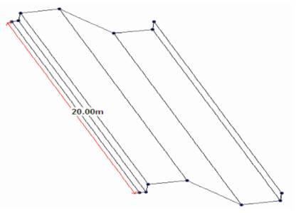
Figure 1. Longitudinal View of Northlight Folded
Plate
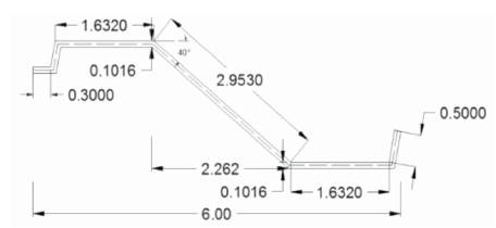
Figure 2. Cross-section of the Northlight Folded
Plate
3. Analysis of the Northlight Folded Plate Using Whitney's
Method
Whitney method of analysis was used for analysis of the
northlight folded plate. Whitney considered the end plates
of the folded plate as cantilevers. This is a simplified
treatment of folded plates due to which the number of
simultaneous equations to be solved is reduced by two. The
Whitney method is applicable for folded plates with width
and thickness of the plates and the intensity of loading
uniform along the length of the plate. Mathematical
computations are greatly simplified by replacing the
uniform load by Fourier loading and considering only the
first term of the series. The plate moments, stresses and
deformations, therefore, vary as sine functions along the
length, have maximum values at mid span.
4. Formulae Used
1. Plate loads were calculated by [10].
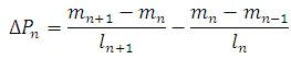
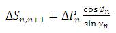
2. Additional plate loads were calculated by :
3. Additional plate loads were calculated by :
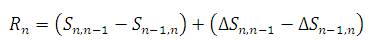
4. Resultant plate loads were calculated by :
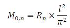
5. Plate moments were calculated by :
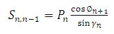
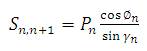
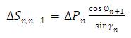
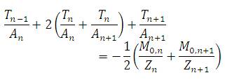
6. Edge – Shear equations were established using the
formula :
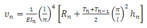
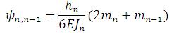
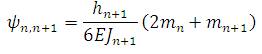
7. Plate deflections were calculated by :
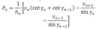
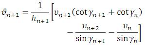
8. Angle changes due to plate deflection were
calculated by :
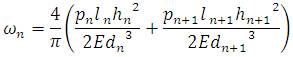
9. Angle changes due to loads were calculated by :
10. Angle changes due to transverse moments were
calculated by :
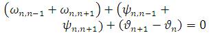
11. The transverse moments of each plate were
computed by considering the total change at each joint
which is equal to zero.
From these values we arrive at the fiber stresses at the other
sections, noting that their distribution along the span follows
a sine curve. Then the fiber stresses are corrected by
multiplying by the factor 1 π3/32. This correction is
applied
as only the first term of Fourier series has been used.
5. Modelling of a Northlight Folded Plate
The northlight folded plate roof structure was modeled
using four noded plate elements in STAAD. Pro, and each
node has six degrees of freedom. The folded plate can be
modeled as a single block as a whole, but application of
loads over the plate as well as the study and analysis at
intermediate points is a difficult task. In order to study the
performance at various critical points, folded plate was
modeled as a fine division of the folded plate into finite elements. The
discretization of folded plate into finite
elements can be done into any number of parts.
Discretization of the folded plate into elements should be
such that the element of the folded plate should represent
the shape of the folded plate. In the present study, the
folded plate was discretized at 1 meter interval as shown in
Figure 3. Details, Geometrical, Trigonometric of the
Northlight Folded Plate are shown in Tables 1, 2, and 3.
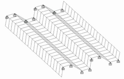
Figure 3. Modelling of the Northlight Folded Plate
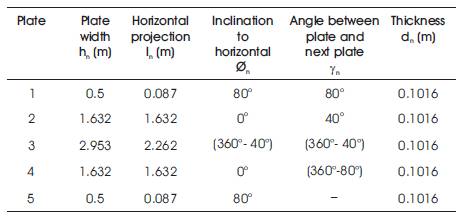
Table 1. Details of the Northlight folded plate
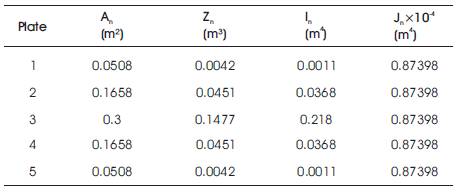
Table 2. Geometrical Properties of Northlight folded
plate
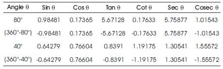
Table 3. Trigonometric Properties of Northlight folded
plate
6. Steps of Modeling
- The northlight folded plate was modeled by assigning
nodes and joining the nodes using four noded plate
elements.
- Now the folded plate structure was discretized into
rectangular elements by generating plate mesh at 1 meter interval
longitudinally.
- Material was assigned to the plate, and the material
properties like density of material, modulus of elasticity,
Poisson's Ratio, were assigned for all plate elements.
- Thickness of the plate was assigned and the fixed
supports for selected nodes were assigned.
- Ridge loads were applied on nodes and the analysis
command was given to run the analysis. Data supplied is to
be processed to complete structure.
- After assigning the loads, Performance of analysis is
done.
- Post processing results in stresses, displacements,
moments of the folded plate model, were studied.
7. Loading on the Northlight Folded Plate Structure
Using dead load and live load, total load was calculated.
From total load, ridge load acting at nodes was
determined. As the analysis of a northlight folded plate was
based on a mathematical approach, the ridge loads were
assigned to nodes in the STAAD. Pro, directly as shown in Figures 4,5,6,7
and 8.
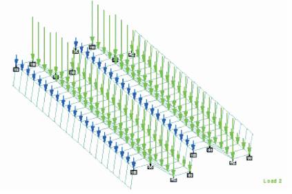
Figure 4. Ridge Load 327.291 kg
Figure 5. Ridge Load 1302.325 kg
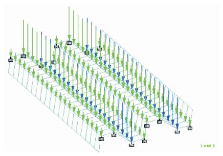
Figure 6. Ridge Load 1232.091 kg
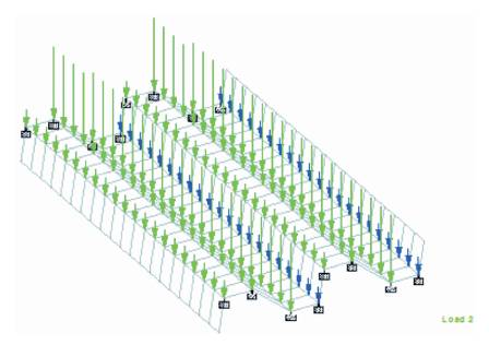
Figure 7. Ridge Load 315.632 kg
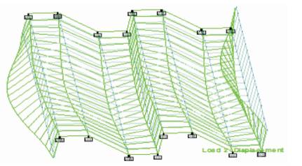
Figure 8. Deflection Profile of Northlight Folded
Plate
8. Results and Discussions
- Maximum stress of 33.601 kg/cm2 was obtained at
node 2 from STAAD.Pro and when calculated manually a
stress of 34.26 kg/cm2 was obtained at the corresponding
node.(tension).
- Maximum stress of 97.789 kg/cm2 was obtained at
node 3 from STAAD.Pro and when calculated manually a
stress of 91.861 kg/cm2 was obtained at the corresponding
node.(compression).
- Maximum stress of 85.539 kg/cm2 was obtained at
node 4 from STAAD.Pro and when calculated manually a
stress of 90.731 kg/cm2 was obtained at the corresponding
node.(tension).
- Maximum nodal displacement of 0.183 mm was
observed at node 10 in positive x-direction and a
maximum nodal displacement of 10.321 mm was
observed at node 101 in negative x-direction.
- Maximum nodal displacement of 0.102 mm was
observed at node 101 in positive y-direction and a
maximum nodal displacement of 7.187 mm was
observed at node 108 in negative y-direction.
- Maximum nodal displacement of 0.901 mm was
observed at nodes 210 and 10 in positive and negative
zdirection.
- Maximum plate deflection of 36.9 mm was observed
in plate 1 in manual analysis.
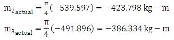
- A transverse moment of 113.840 kg-m was obtained at
node 3 from STAAD.Pro and when calculated manually a
moment of 539.597 kg-m was obtained at the
corresponding node.
- A transverse moment of 1835.675 kg-m was obtained
at node 4 from STAAD.Pro and when calculated manually a
moment of 491.896 kg-m was obtained at the
corresponding node.
- It was observed that the value of stress obtained from
STAAD.Pro at node 2 was 1.92% less than the manually
calculated stress at the corresponding node.
- It was observed that the value of stress obtained from
STAAD.Pro at node 3 was 6.45% more than the manually calculated
stress at the corresponding node.
- It was observed that the value of stress obtained from
STAAD.Pro at node 4 was 5.72% less than the manually
calculated stress at the corresponding node.
- It was observed that, in manual analysis the maximum
stresses in plates can be compared with the STAAD.Pro
output.
- Plate deflections were not obtained in the STAAD.Pro
package, whereas, they can be calculated manually.
- Nodal displacements were obtained in the STAAD.Pro,
whereas, they cannot be calculated manually.
- It was observed that the value of transverse moment
obtained from STAAD.Pro at node 3 was 78.90% more than
the manually calculated moment at the corresponding
node.
- It was observed that the value of transverse moment
obtained from STAAD.Pro at node 4 was 273.18% more
than the manually calculated moment at the
corresponding node.
8.1 Actual transverse moments
8.2 Longitudinal stresses
Longitudinal stresses are obtained by multiplying the fiber
stresses obtained with a factor
Conclusions
- The value of stress obtained from STAAD.Pro at node 2 is
less than the manually calculated stress at the
corresponding node 3.
- The value of stress obtained from STAAD.Pro at node 3 is
more than the manually calculated stress at the
corresponding node 4.
- The value of stress obtained from STAAD.Pro at node 4 is
less than the manually calculated stress at the corresponding node
5.
- The transverse moments calculated manually were
conservative when compared to STAAD.Pro results.
- Maximum nodal displacements of 0.183 mm, 0.102
mm and 0.901 mm occurred at nodes 10, 101, 210
respectively in positive x, y and z directions.
- Maximum nodal displacements of 10.321 mm, 7.187
mm and 0.901 mm occurred at nodes 101, 108, 10
respectively in negative x, y and z directions.
Scope for Future Study
- The static analysis was performed for the northlight
folded plate roof in the present study. Further work can be
carried out to obtain more accurate values when
compared to the manually obtained results.
- Wind load analysis for different basic wind speeds can
be performed for the northlight folded plate roof in the
further work.
References
[1]. Elie A. Sehnoui, (1961). “Computer Analysis of
Folded
Plates”, Massachusetts Institute of Technology.
[2]. Building Digest 21, (1963). “Folded plate
Roofs”, Central
Building Research Institute, Roorkee,
[3]. Fredrick Mitchell Graham, (1966). “The Behavior
of A
Folded Plate Roof System”, Iowa State University of Science
and Technology.
[4]. Rockey K.C, Evans H.R., (1976). “An
Experimental and
Finite Element Study of the Behavior of Folded Plate Roofs Containing
Large Openings”, IABSE Publications.
[5]. Ramaswamy G.S., (1986). Design and Construction of
Concrete Shell Roofs, McGraw-Hill Publishing Company,
New Delhi.
[6]. Bandyopadhyay J.N., Laad P.K.,
(1990).“Comparative Analysis of Folded Plate Structures”.
Computers & Structures, Vol. 36, No. 2, pp. 291-296.
[7]. Indian Standard code of practice for design
loads(other than earthquake) for buildings and structures
PART 1 DEAD LOADS – unit weights of building materials and
stored materials IS: 875 (Part 1) – 1997 reaffirmed.
[8]. Indian Standard code of practice for design loads
(other than earthquake) for buildings and structures PART 2
IMPOSED LOADS IS: 875 (Part 2) – 1997 reaffirmed.
[9]. Indian Standard criteria for design of reinforced
concrete shell structures and folded plates IS: 2210 – 2003
reaffirmed.
10. Raamachandran J., (2013). Thin Shells Theory &
Problems; Universities Press (India) Private Limited.
[11]. Arun Tejani, Parikh A.A., (2013). “Computer
Aided
Wind Analysis on R.C.C Folded Plate”. Indian Journal of
Research, ISSN-2250-1991, Vol. 3, No. 4.
[12]. Tibu Chacko, Ramadass.S and Jayasree
Ramanujan, (2013). “Parametric Study of Transverse and
Longitudinal Moments of Trough Type Folded Plate Roofs
Using Ansys”. American Journal of Engineering Research,
e-ISSN: 2320-0847, p-ISSN: 2320-0936, Vol. 4, pp. 22-28.