Table 1. Physical Properties of Cement
Self-computing concrete (SCC) is a highly workable type of concrete which does not require any further external compaction or vibration. Super plasticizers are used to increase the ease and flow ability of SCC to a remarkable extent. Many experiments have been conducted by researchers to understand the properties and behaviour of SCC. Validation of finite element modelling with experimental data helps engineers in parametrically characterizing and analyzing the large structural components, which in turn saves time, energy and cost. Incorporation of fibres into SCC to increase its flexural strength is an ongoing research which has gained worldwide attention. This study is an effort to evaluate the behaviour of SCC with steel fibres by incorporating nano silica. Nan-su method of mix design is adopted in this study to obtain the control mix of SCC (SCC-CM) through experimental research. This analysis of FE modelling using Abaqus / CAE proposes to study the behaviour of SCC beam with and without incorporation of nano-silica and steel fibre. Analytical response of SCC beam is in good correspondence with the experimental results which is then compared to SSC beam containing nano-silica and steel fibres (SCC-NS). Response obtained from FEM indicates that SCC beam with nano-silica and steel fibre exhibits significant improvement in load deflection comparison at first crack and failure load, resistance against deflection, load carrying capacity and flexural strength in comparison with normal SCC (NSCC) beam.
Self-compacting concrete or self-consolidating concrete or super workable concrete is a type of concrete which possesses self-levelling ability and spreads or compacts by its own weight without the employment of vibration or any external force. Previously, self-compacting concrete has also been called as 'High Performance Concrete' (HPC). In 1980, a Japan-based scientist Hajime Okamura invented SCC to address common problems in conventional concrete such as improper compaction, honey-comb formation, less strength due to non-uniformity. The first incorporation of SCC has been seen in transportation structures built in Sweden in the 1990s.
The constituents used in self-compacting concrete are same as that of normally vibrated concrete. In SCC w/c ratio, size of aggregate, grading, aggregate shape and size, filler material and dosage of super plasticizer are varied to attain the required workability, passing and filling ability. For reducing the usage of cement content in SCC, pozzolanic materials such as GGBS, pumice powder, fly ash etc., are added.
Various experiments have been conducted to study the properties and behaviour of SCC in fresh and hardened state.
Ben Aicha et al. (2017), studied the mutual relationship between bleeding and the rheological properties of 29 SCC mixes. Bleeding decreases significantly as the Super Plasticizer (SP), limestone filler, Viscosity Modifying Agent (VMA), and Silica Fume (SF) content increases. It has been found that bleeding index increases with increasing slump flow value, and L-box ratio decreases with increasing Vifunnel time, plastic viscosity, yield stress and entrained air content. Tavakoli et al. (2017) experimentally investigated the effects of cyclic loading rate on the mechanical behaviour of reinforced SCC beams and found that SCC beams showed a significant change in behaviour before and after the yielding zone. There has been enhancement of energy dissipation capacity and equivalent viscous damping with the increase in loading rate. In the recent times, experiments have been carried out on the use of recycled aggregates. Rajhans et al. (2018) tried to develop SCC using Construction and Demolition (C & D) waste with recycled aggregates. The aim of the study has been to evaluate the changes in micro structure and mechanical properties of the developed SCC. Based on the results, it has been observed that there has been an improvement in properties of developed SCC with 100% recycled aggregates which has been confirmed by micro structure micrographs. In another study conducted by Nieto et al. (2019), the results showed that using up to 20% RCA had negligible impact on the characteristics of SCC similar to the results obtained by Manzi et al. (2017), where 40% replacement of recycled aggregates were used.
Incorporation of fibres of different kinds have been studied in the past to increase the flexural strength of SCC. You et al. (2011) studied on self consolidating concrete beams with low reinforcement ratios and concluded that the flexural ductility dropped due to the addition of fibres into the beam with minimum longitudinal reinforcement ratio. The flexural ductility decreased with the increase in fibre aspect ratio. Paul et al. (2016) conducted experimental study on SCC incorporating steel fibre reinforcements of hooked end type with varying percentages of 0, 0.4, 0.8 and 1.2 and observed that workability decreased with the increase in volume of fibres whereas ductility and other mechanical properties of SCC were enhanced for optimum level of steel fibre at 0.8%. Similarly, Mahmod et al. (2018) studied the effect of steel fibres on mechanical properties of SCC. The results showed that the flexural and compressive strength were enhanced but workability and flowability were decreased due to SF addition. Whereas a study conducted by Okeh et al. (2019) used hooked end steel fibre at 0.75% and 1% fibre content for single and double hooked end steel fibres respectively and combined with straight micro (MIC) steel fibers in SCC with two different types of steel fibre hybridization. The results demonstrated the increase in tensile strength and load carrying capacities by hybridization of steel fibres. A study conducted by Aamir et al. (2017) states that compared to other fibres, steel fibres possess more serviceability, mechanical properties and durability. The conventional steel reinforcement can be completely replaced by micro steel fibres in some types of structures such as slabs, wall and foundation as they give enough strength and ductility. The results obtained indicate that the optimum percentage of steel fibre to improve flexural strength has been 0.75% and compressive strength has been 1%. Khaloo et al. (2014) used two mix designs of 40 MPa and 60 MPa, i.e., for medium strength and high strength concrete and took four different steel fibres volume fractions, namely, 0.5%, 1%, 1.5%, and 2%, to study the effect of steel fibres on rheological properties and mechanical properties of SCC samples. The result showed that the splitting tensile strength of medium strength and high strength SCC specimens were increased by 28.5% and 17.1% by adding 2% fibre volume fraction.
The use of nano particles in concrete is gaining worldwide attention due to their ability to enhance mechanical properties such as compressive strength, toughness etc. Various experiments have been carried out on the use of silica in concrete. The fresh and rheological behaviour of nano-silica and fly-ash-blended SCC has been studied by Güneyisi et al. (2015). Four SCC mixes were prepared by replacing total binder content with nano silica in ratio of 0, 2, 4, and 6%. The author observed that nano silica aggravates the fresh property of SCC while fly ash improves it. Also, Achara et al. (2019) studied the bond behaviour of nano-silica-modified SC engineering cementitious composite (SC- ECC) by employing response surface methodology. The use of nano-silica particles with polyvinyl alcohol fibre enhanced the ductility of the material. Similarly, Asif and Mehta (2019) conducted experimental study on self compacting concrete using nano silica replacement in ratio of 3, 4 and 5%. L-box, V-funnel and slump test were conducted to analyze the fresh propertiesof SCC. The test observed that there has been significant increase in compressive, tensile and flexural properties with the addition of nano-silica. The optimum dosage has been found to be 4%. Both Subramanian and Nadu (2014) and Hameed et al. (2020) studied the strength and durability of SCC by including micro and nano silica. According to the authors, the best combination to obtain more strength is to use both nano and micro silica. They found that the tensile strength increased from 16.67% to 34.87% and compressive strength from 29.32 to 48% for replacements ratios of 2.5 to 10% of colloidal nano silica respectively and the optimum dosage for modulus of elasticity has been 2.5% of colloidal nano silica.
Efforts have been made to blend both nano silica and steel fibres. Beigi et al. (2013) conducted experimental research onself compacting concrete by combining nano silica and fibres (steel, glass, polypropylene). The author evaluated the combined effect of nano silica and fibres on mechanical properties such as toughness, modulus of elasticity, rheological properties, durability characteristics etc. The results obtained from the experiments proved that includingnano silica and fibres at optimum percentages significantly improved the mechanical and durability properties of SCC mix. The optimum percentage of nano silica has been found to be 4% of the weight of cement and steel fibre has been 0.5% of the total volume.
FEM software is used widely to analyze concrete structures andAbaqus / CAE is the most used software in India.
Research is being carried out in the last few decades on the use of FEM. Faherty (1972) has been one of the pioneers to conduct experimentations on the application of FEM for the validation of experimental results with respect to RC beams. One of the recent works by Lemuel Thompson Yaw et al. (2017) showed comparative studies on experimental and analytical results of reinforced SCC beam. Analytical results were obtained using Abaqus / CAE software. The main aim has been to model the SCC beam in abaqus in order to predict appropriate results without performing experimental investigations. The author studied failure load, deflection at failure load, deflection at mid span and compared these results with experimental and theoretical results. The average errors in developed FEM model were 7.8% and 2.3% for deflection and ultimate failure load respectively.
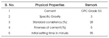
Cement used for SCC is same as that of normal concrete. The present study used Ordinary Portland Cement of 53 grade (Birla Super) as per Bureau of Indian Standard (1987). Testing has been conducted according to the Bureau of Indian Standard (1998). The properties of cement are tabulated in Table 1.
Table 1. Physical Properties of Cement
Crushed or natural sand or M-sand is suitable for SCC. Since SCC contains more fines and is well graded, it plays a major role in determining fresh properties of SCC. Civil engineering projects have always been on the rise in the last century and the limited availability of river sand has given way to the use of M-sand in its place. M-sand particle size should be less than 4.75 mm and the physical properties of M-sand should be tested according to Bureau of Indian Standard (1970) and Bureau of Indian Standard (1963). Table 2 shows the physical properties of M- sand.
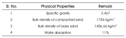
Table 2. Physical Properties of M-sand
The nominal size of coarse aggregate is 10 mm to 12.5 mm. Coarse aggregate should enter through 12.5 mm sieve and should be retained in 10 mm sieve. Physical properties of coarse aggregates are tested as per Bureau of Indian Standard (1963). and the same are listed in Table 3.
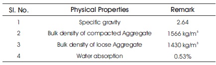
Table 3. Physical Properties of Coarse Aggregate
Nowadays, fly ash is widely used as an alternative for cement due to its pozzolanic and cementitious properties. Large amount of CO is released during the manufacture 2 of cement which causes heavy air pollution. To avoid this adverse effect on environment, alternative materials should be used which possess cementitious properties. Fly ash is a by product of coal industry and can be used as a replacement for cement. Class F fly ash is taken for the present study. The physical properties of fly ash are listed below (Jalal et al., 2015).
Less water-cement ratio is adopted in SCC to avoid segregation and bleeding. For obtaining required flow ability, workability and fresh properties, super plasticizers are used. These are water-reducing agents and reduce water up to 20%. This study uses Master Glenium Sky 8233 which is reddish brown in colour and has specific gravity of 1.08. Normal dosage of SP ranges from 0.5 to 2%.
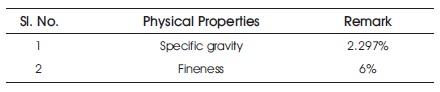
Table 4. Physical Properties of Fly Ash
As normally vibrated concrete has less resistance to the propagation of cracks, steel fibres are added to avoid the formation and growth of cracks. Steel fibres are used in this study and their properties are mentioned in Table 5.
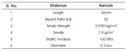
Table 5. Physical Properties of Steel Fibre
Nano-particle is a particle whose dimension is less than 100 nm at least in one dimension. Incorporation of nano-silica in SCC increases the mechanical and physical properties and fineness of the concrete mix whereas decreases the flow ability and setting time of OPC. The properties of nanosilica are listed in Table 6.
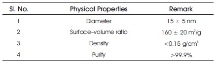
Table 6. Physical Properties of Nano-Silica
The properties of the materials used is listed in Table 7.
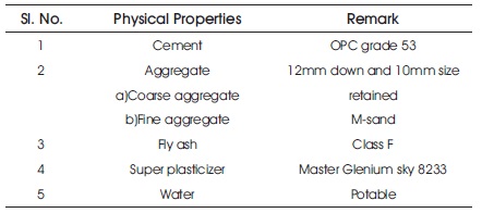
Table 7. Properties of Materials Used
Self-compacting concrete is an emerging construction material which is largely being used in the recent times to overcome and avoid problems of normally vibrated concrete. SCC does not have a code book and standard mix design.
Various theories and mix design methods are proposed by researchers. Nan-Su has been one among the researchers who had proposed mix design for SCC. Hence this method is widely known as 'Nan-Su method of mix design' for SCC. In this study, we have adopted Nan-Su method of mix design since it is cost effective, simple and gives required fresh and hardened properties. Nan-Su's coefficient is used to calculate cement required for the mix, water to cement (w/c) ratio, fine aggregate content, coarse aggregate content and super-plasticizer content. Absolute volume method is used for carrying out proportions of these trial mixes. Therefore, to achieve different proportions of SCC, the specimens of size 150 mm x 150 mm x 150 mm cubes were casted and tested.
Fixing the SP dosage is a very crucial step in achieving SCC. All other material quantities are fixed before this procedure such as cement, fine aggregate, coarse aggregate and fly ash. Water cement ratio is also fixed and SP dosage is varied starting from 0.5%.
If a concrete mix must be categorized as SCC, it is mandatory that the concrete should satisfy filling ability, passing ability and segregation resistance. EFNARC gives guidelines for determining fresh properties of SCC. Although there are various methods to determine fresh properties of SCC, there is none to characterize the fresh property. Figure 1 shows the photographic image of the performed Slump flow test and V-funnel test. L-box test and U-box test is shown in Figure 2.
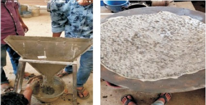
Figure 1. Slump Flow Test and V-Funnel Test
The ability of the concrete to flow on a horizontal surface in the absence of any obstruction is determined using slump flow test. The filling ability and segregation of SCC are studied by this parameter. Inverted slump cone is filled with SCC and lifted after which the flow spread and flow time (T50) are measured. Flow spread is the spread of concrete on horizontal surface and flow time is the time taken by SCC to spread for 500 mm. Test has been conducted as per EFNARC guidelines.
Time required for a given volume of SCC to pass through narrow sections may be defined as the V-funnel flow time. This test helps in understanding the filling ability and passing ability in narrow regions of SCC.
L-box helps to study the movement or passing ability of SCC in congested reinforcement regions. This test is conducted to know the passing and filling ability of SCC through narrow regions. Height of concrete on both sides (i.e., towards vertical box and horizontal box side) are measured after the gate is lifted and the concrete is permitted to pass through the gaps between steel bars.
U-box test is also conducted to study the filling and passing ability of concrete. In U-box, SCC is poured in one limb and then allowed to flow to the adjacent limb. The height difference of SCC between two limbs is measured to obtain the filling height of SCC. The test has been conducted in accordance with EFNARC guidelines. According to the above guidelines filling height should be between 0 and 30 mm.
To test the hardened properties of concrete, compressive test has been conducted on 100 mm x 100 mm x 100 mm specimen using universal testing machine as shown in Figure 3. By trial and error method, the optimum percentage of nano-silica obtained experimentally has been 4% of the weight of cement. By incorporating nanosilica to SCC (SCC-S), 29.23% increase in compressive strength was observed.
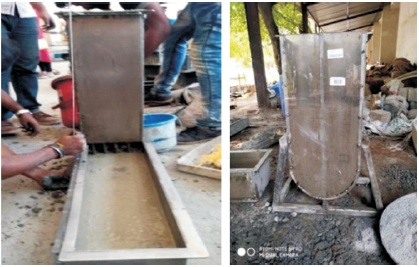
Figure 2. L-box and U-box test
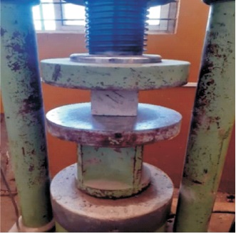
Figure 3. Compression Testing of Cube
Multi-linear regression analysis (MLRA) model is performed using excel. In this analysis as the number of variables increase the accuracy increases. Percentage of nanosilica and steel fibres are independent variables and tensile strength, compressive strength, split tensile strength are dependent variables. By entering all the variables in excel sheet, regression analysis has been performed.
To understand the flexural behavior, failure load, deflection properties and flexural strength of SCC beams under 4- point testing, Abaqus CAE is used to model and interpret the response. The FE model of SCC beam is shown in Figure 4. The response parameter of the output depends on the definition of material properties. Therefore, it is crucial to note down the specification and properties of the material. The non-linear analysis has been conducted on SCC beams by considering the following properties from the literature and previous experimental works. The software requires data of both compressive and tensile behaviour of the SCC member. The compressive uniaxial stressstrain curve, as well as tensile curve has been used to obtain the non-linear stress strain behaviour of the SCC model. The flowchart of FE Modelling is shown in Figure 5.
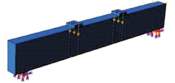
Figure 4. FE Model of SCC Beam
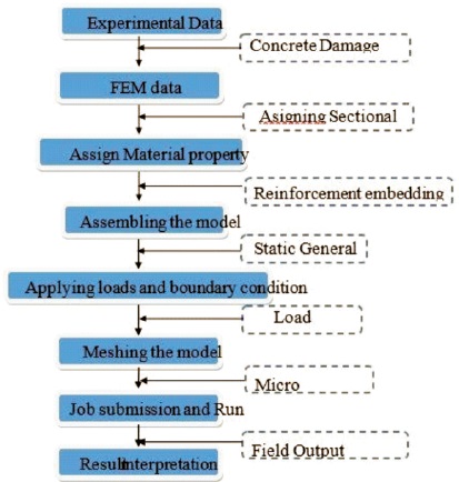
Figure 5. Flowchart of FE Modelling
To model and analyze the SCC beam with and without nano-silica and steel fibres, Abaqus CAE software has been used. The size of the beam considered has been 2000 mm x 110 mm x 275 mm. Abaqus is a very powerful software used for the FEM analysis as it consists of several inbuilt material models which help in the non-linear analysis of the elements.
Experimental studies and analytical studies were made on NSCC and SCC-NS. This chapter deals with experimental results of SCC-CM in fresh state, its compressive strength and analytical results of SCC and SCC-NS beams.
Water cement ratio is fixed and SP dosage is varied starting from 0.5%. The required workability and all the fresh state parameters were satisfied in accordance with EFNARC for SP dosage of 0.88%. Hence 0.88% has been fixed as the optimum dosage of SP for the control mix. Table 8 gives the value of slump flow for different dosages of SP.
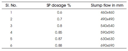
Table 8. Trial Mix Result of SCC Mix
To find fresh properties of SCC, four methods - slump flow, Vfunnel, L-box and U-box are adopted. All the results obtained are tabulated in Table 9 along with the EFNARC guidelines. Segregation and bleeding are not observed. Similarly, V-funnel, L-box, U-box test gives satisfactory result for SCC.
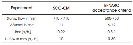
Table 9. Fresh Properties of SCC-CM
Based on the results from the experiment, it has been noted that, rapid increase in strength is observed in 7 days for SCC- S cube when compared to 28 days testing. For SCCCM cube, normal strength has been accomplished as per grade of the concrete (M30). Compressive Strength of SCCCM and SCC-S is tabulated in Table 10 for both 7 days and 28 days. It is illustrated as a graph in Figure 6.
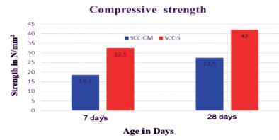
Figure 6. Compressive Strength of SCC-CM and SCC-S
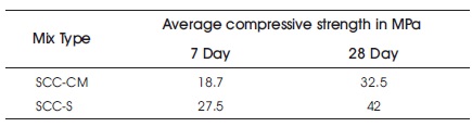
Table 10. Compressive Strength of SCC-CM and SCC-S
Multi-linear regression analysis (MLRA) model is done on excel. Percentage of nano silica and steel fibres are independent variables and tensile strength, compressive strength, split tensile strength are dependent variables. By entering all the variables on the excel sheet, regression analysis has been performed. Equation (1) has been derived using the following results obtained from excel (Uyanık & Güler, 2013). The results are shown in Table 11.
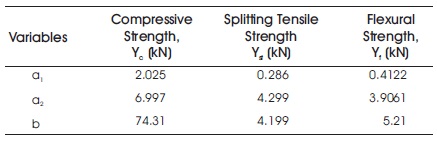
Table 11. Results from MLRA
where Y is the strength of SCC, x1 is the percentage of nano-silica, x2 is the percentage of steel fibres and a1, a2, and b are variables. This equation is valid up to x1 = 6% and x2= 0.5%.
To understand the stress-strain behavior, flexural behavior, failure load and deflection properties of SCC beams under 4-point testing, Abaqus CAE is used to model and interpret the response. The response parameter of the output depends on the definition of material properties. Hence it is necessary to be aware of the specification and properties of the material. The non-linear analysis has been conducted on SCC beams by considering the following properties from literature and previous experimental works. The software requires the data of both compressive and tensile behaviour of the SCC member. The compressive uniaxial stress-strain curve, as well as tensile has been was used to obtain the non-linear stress-strain behaviour of the SCC model (Hafezolghorani et al., 2017).
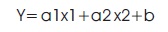
The first crack in the beam occurs when stress in the beam exceeds the modulus of rupture. This is due to flexural crack in the beam and constant moment region. The beam exhibits elastic property and linear load deflection curve is seen till the first crack is observed, i.e., from 0 kN to load on the beam at initial crack. The same is shown in Table12.
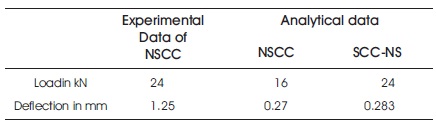
Table 12. Load and Deflection Comparison of Beam at First Cracking
Flexural strength is the ability of the beam to withstand the load at the bending point. It is usually measured in MPa. The 2-point bending test method has been used in this study to evaluate flexural strength. The study and test procedures were conducted in accordance with Bureau of Indian Standard (1959). While calculating flexural strength theoretically using experimental data, load at first crack or yield load is considered as 'failure load'. Therefore from FEM, load at first crack is considered for calculating flexural strength. Load at first crack is 16 kN and 24.5 kN for NSCC and SCC NS beams respectively and these loads are considered to calculate flexural strength. Damage distribution in tension zone for SCC-NS and NSCC is shown in Figure 7 and Figure 8 respectively. The optimum percentage of nano-silica and steel fibre used for SCC-NS beam were 4% of weight of the cement and 0.5% of volume of concrete.
For NSCC beam y=3Pa/(bd )
y=(3×16×10 ×850)/(110×275 =4.9 MPa
For SCC-NS beam y=3Pa/(bd )
y=(3×24.5×10 ×850)/(110×275 )=7.51 MPa
where 'a' is the distance from the crack occurred to the nearest support, 'P' is failure load, 'b' is the width of the beam, 'd' stands for depth of the beam, 'Y' is flexural strength.
Figure 7. SCC-NS Damage Distribution in Tension Zone
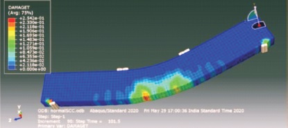
Figure 8. NSCC Damage Distribution in Tension Zone
In Abaqus / CAE, it is not possible to obtain cracking pattern of beam but it is possible to obtain response of damage distribution in the beam. By using DAMAGET function in the software, damage distribution of the beam in tension zone is obtained and this is considered as the path of the cracking pattern in NSCC beam.
Ultimate failure load or fracture point of the beam is that point beyond which the beam is not capable of withstanding any further loads and has reached its maximum level of load carrying capacity. In experimental investigation, the failure load can be noted when the beam totally collapses. However, it is not so with respect to FEM. To obtain the failure load in FEM, the last or maximum point of load is considered from the load vs deflection graph. The deflection for failure load in the beam has been measured at the bottom of mid span of the beam.
Remarkable improvement is seen in load-bearing capacity and deflection of SCC-NS beam when compared to NSCC beam. Load-deflection comparison of beam at failure load is listed in Table 13. The curve showing the load vs deflection of SCC-NS and NSCC beam is shown in Figure 9 and Figure 10 respectively. Significant increase is observed in the failure load capacity of SCC-NS whereas the deflection remains almost the same as that of NSCC beam. This curve is helpful to obtain the load at first visible crack from FEM which suits the experimental data. Full load vs deflection curve is considered and major change in the gradient of the curve is noted to obtain the load at first visible crack and this makes easy assessment of load and deflection comparison of first visible crack. The last or maximum point of load is obtained from this curve and it is considered as the failure load in FEM. Load and deflection comparison of the beam at both failure load and at first crack are obtained from this curve.
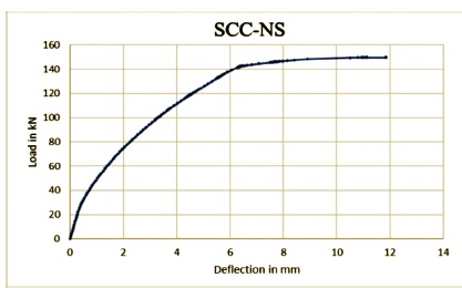
Figure 9. Load vs Deflection of SCC-NS
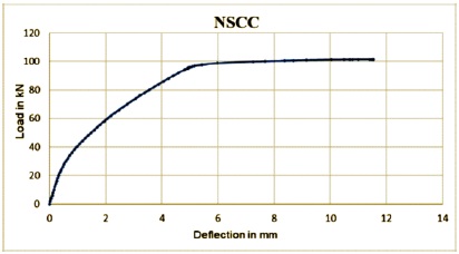
Figure 10. Load vs Deflection of NSCC
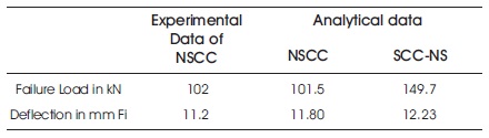
Table 13. Load and Deflection Comparison of Beam at Failure Load
Based on the experimental and analytical studies, the conclusions drawn are as follows:
By using class F fly ash, SCC has been achieved from Nansu method of mix design by following the guidelines specified by EFNARC.