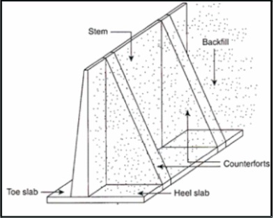
Figure 1. Counterfort Retaining Wall
The design of rigid retaining wall (Cantilever, Counterfort, Buttress) is based on pressure exerted by the retaining material, wall slope, height, ease of construction and stability. When the retaining wall height is more than 8 m, the selection of extra supports, i.e., either counterforts or buttresses is based upon the designer's experience. By conducting comparative study on resisting forces for varying heights, the behavior of these supports on retaining wall can be depicted. The depiction of forces can be achieved by running an analysis in STAAD.Pro with preliminary dimensions and soil parameters respectively. Resisting forces from counterfort and buttress supports on retaining wall are equal when the height is in between 9 m to 24 m but buttress support has shown less resisting forces when the height is less than 9 m.
Rapid increase in urbanization and industrialization is leading to the development of infrastructure in both onshore and offshore environments all over India. Construction of retaining wall is carried out in the infrastructural development activities like hillside farming or roadway overpasses, preventing soil erosion, aesthetic purposes and stabilizing sloped yards. A retaining wall is a structure designed and constructed to resist the lateral pressure of soil, when there is a desired change in ground elevation that exceeds the angle of repose of the soil (Ching et al., 2006). Based on the availability and suitability of material, there are two types of retaining walls viz., Rigid and Flexible. The retaining wall is analyzed based on soil pressure (Coulomb, 1776) and material properties (Terzaghi, 1943) viz., angle of internal friction (Ø), unit weight (λd) of the earth retained. Patil and Bagban (2015) stated d that cantilever retaining walls are economically suited for wall heights up to 6 m. When the height of earth retained is more than 8 m, extra supports named as counterforts or buttresses as shown in Figure 1 and 2 are introduced in order to avoid the failure either by overturning, sliding or tension. Nagre et al. (2017) had concluded that stepped cantilever wall is more feasible than Gabion and Segmental type of retaining walls. Maen Farhat and Mohsen Issa (2017) had compared the design, structural efficiency, and structural performance between prefabricated counterfort retaining wall system and an existing counterfort cast-in-place concrete retaining wall system ( Kezdi, 1958). Based on literature survey, it has been observed that a lot of analysis had been carried out on the retaining walls and experts evaluated the economy, feasibility and structural performance of retaining wall. But the criterion of selection of counterforts or buttresses as supports for cantilever retaining wall remains unexplored. This study is a novel attempt made to state the suitability of supports for retaining wall of heights between 3 m to 24 m assuming that the retaining wall is stable under overturning, sliding and tension.
Figure 1. Counterfort Retaining Wall
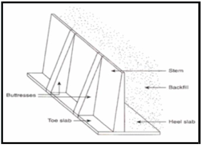
Figure 2. Buttress Retaining Wall
STAAD.Pro is used to estimate the values of resisting forces and moments in cantilever, counterfort and buttress retaining walls at origin from 3 m to 24 m and comparative results are illustrated. Typical 3D model of counterfort retaining wall is shown in Figure 3.
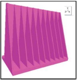
Figure 3. Typical 3D Model Counterfort Retaining Wall
The cantilever, counterfort and buttresses retaining wall models has been developed with preliminary dimensions (Raju & Pranesh, 2008) with respect to the overall height (H) every 3 m interval up to 24 m. The base slab width and thickness, toe and heel projections and stem thickness are stated.
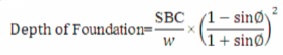
The Earth pressure based on assumed soil parameters stated has been estimated with reference to Wang (2000).
In this study, isotropic concrete of compressive strength 30 MPa with density 23.5 kN/m3 has been assumed.
As per preliminary dimensions, nodes are generated and plate elements are assigned. Further, quadrilateral meshing has been adopted to get stress strain contours and bottom nodes are assigned as fixed supports. Typical stress contour and loading diagram is shown in Figure 4 and Figure 5 respectively. Based on the height of the retaining wall, the earth pressure on stem and dead load above heel slab has been calculated and applied to assess the forces.
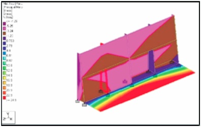
Figure 4. Principal Stress Contour
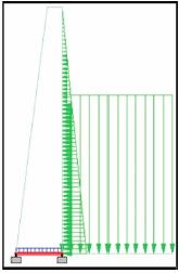
Figure 5. Supports and Loading Diagram
The resisting forces Fx , Fy , Fz in kN and resisting moments Mx, My, Mz in kN-m for cantilever retaining wall are shown in Table 1 and are compared with counterfort and buttress retaining wall.
The comparison of forces and moments of counterfort and buttress retaining walls in percentile with respect to cantilever retaining wall as per Table 1 are estimated and are shown in Table 2. The same are plotted in Figure 6, 7 and 8.
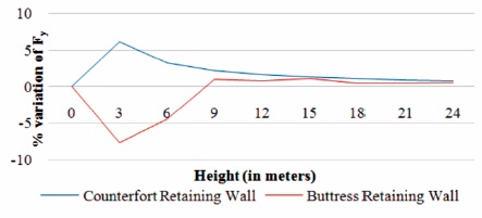
Figure 6. Comparison of Force (Fy) of Counterfort Retaining Wall & Buttress Retaining Wall with respect to Cantilever Retaining Wall
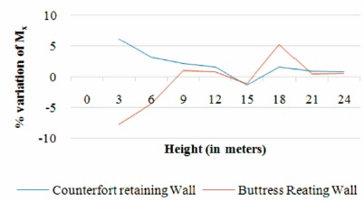
Figure 7. Comparison of Moment (Mx) of Counterfort Retaining Wall & Buttress Retaining Wall with respect to Cantilever Retaining Wall
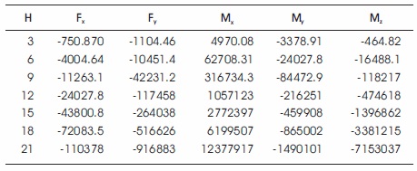
Table 1. Resisting Force Values of Cantilever Retaining Wall
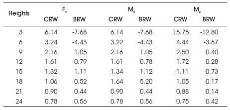
Table 2. Percentage Increase in Resisting Forces with respect to Cantilever Retaining Wall
From Figures 6, 7, and 8, it is evident that the resisting forces and moments for counterfort retaining wall has shown increasing trend up to 3 m and a decreasing trend up to 9 m whereas buttress support has shown an opposite trend.
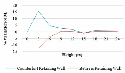
Figure 8. Comparison of Moment (Mz) of Counterfort Retaining Wall & Buttress Retaining Wall with respect Cantilever Retaining Wall
From Figures 6, 7, and 8, the resisting forces exerted by the supports on retaining wall follows same trend line. However, if the retaining wall height is between 15 to 21 m, buttress support gives better performance. Hence, buttress support is suggested. On the other hand, when the height of wall is less than 9 m, buttress supports shall be avoided and counterfort supports shall be chosen for design. The comparative study on resisting forces for varying heights has been conducted, and the behavior of these supports on retaining wall has been depicted in this study.