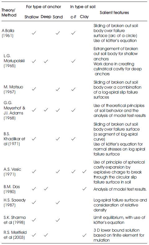
Table 1. Summary of theories and methods for predicting ultimate pulling load on anchor foundation
Foundations of several civil engineering structures are required to be designed as anchor foundations. The analysis and design of deep anchors in clays are considered by very few researchers and investigators in the reported literature. Conspicuously this aspect appears to be inadequately investigated. The paper attempts to highlight the analysis of deep anchors in soft clays by proposing an idealized load transfer mechanism and the mode of failure of this soil-foundation system. The presently used foundation element for resting light structures on expansive soils, in the form of an underreamed pile, is proposed to be used as an effective deep anchor. With reference to this soil-under-reamed pile system, analytical as well as experimental studies are carried out. The analysis led to a simple and easy way to use equation for estimating the pullout load capacity of ground anchors, in clays of medium to soft consistency. In order to evaluate the validity of theoretical formulation, a detailed experimental program was undertaken. The model studies incorporated under-reamed pile models of three shaft diameters with under-reaming ratio of 2.5, four values of depth factors. The clay soil used in studies had cu=0.24 kg/cm2 . The observed failure loads were compared with the computed values which revealed that, for under-reamed piles having length larger than 8 times the shaft diameter, there was very close agreement between the above two values.
Problems related to anchoring the structures subjected to vertical uplift forces or loads, acting solely or in combination with other lateral or inclined forces, are numerous in civil engineering practice. Some of the typical cases wherein the action of vertical upward load is required to be considered in the design of foundation are: pylons for transmission lines, tall tower like structures, radio relay tower frames, floors of dry docks, anchoring the ends of main strands of suspension bridges, light structures with underground basement, foundation of tension leg offshore platforms, etc. Quite often these structures are founded in clayey soils. This aspect of anchor foundation in clay (especially soft clays) appears to be inadequately investigated analytically in the present state of the art. The paper highlights an idealized simple load transfer mechanism for anchor foundation in saturated soft clay alongwith mathematical formulation to evolve an equation to predict the pullout load at soil-foundation system failure. It also describes the model studies carried out to verify the validity of theoretical analysis.
Underreamed pile is essentially a bored cast-in-situ concrete pile, provided with an enlarged bottom in the form of underreamed bulb. The pile is developed in India, mainly by CBRI, New Delhi, to function as an effective and economical foundation for light structures in expansive soil (colloquially called as black cotton soil in India). Under the action of vertical downward loads from superstructure, the pile derives larger load carrying capacity due to increased base area of the pile bottom and reduces the settlement of structure. Besides, the enlarged bulb founded in stable zone of expansive soil ground at site provides good anchoring effect against the structure getting uplifted during swelling of soil in rainy season. These piles are extensively used in India as its construction is a simple process requiring available personnel and equipment. As the more effective anchor foundation is essentially in the form of vertical slender structural element with increased lateral size at bottom, the conventional underreamed pile can function as effective anchor foundation. Considering a pile of shaft diameter ds with length L and underreamed bulb diameter Db , the parameters characterizing the form and shape of an underreamed pile are:
The pile with shaft diameter from 20 to 40 cm with underreaming ratio of 2.5 can be easily constructed in clay and hence such forms are commonly used in most of the field constructions.
The estimation of the pulling load causing 'failure' of the foundation-soil system is perhaps the most important, but very complex aspect in the design of anchor foundation. Prior to about 1960, the methods of computing the pullout resistance of anchor foundations were mostly empirical in nature or were based on highly idealized, and approximate failure mechanisms. The attempts in systematic analysis of anchor were made thereafter beginning with Balla's theory (1961). Over a period of last 50 years, many investigators and researchers have contributed immensely towards theoretical analysis as well as in understanding the behavioral aspects of anchor foundation. L.G. Mariupolskii, A.S. Vesic, G.G. Meyerhof, M.Matsuo, H.B. Sutherland, E.A. Dickin, T.H. Hanna, J.D. Geddes, E.J. Murray, K.S. Subbarao, B.M. Das, R.K. Rowe, E.H. Davis, H.S. Saeedy, P.J. Pise, R.S. Marifield, etc are few names of the contributors in anchor foundation, besides large number of other investigators. On perusal of the literature, it is noticeable that most of the experimental investigations (model studies) have been carried out for anchors (especially shallow type) in sands or non-plastic c-Φ soils. The model studies on anchors in cohesive soils are distinctly very limited. On the analytical side, the theoretical formulations for predicting the pullout capacity of shallow plate anchors in sandy and c-Φ soils are widely considered, whereas for deep anchors in clays, the mathematical formulation is attempted by just couple of investigators. Table 1 gives summary of some of the theories and methods for computing the pullout capacity of anchor foundation. It is evident that considering the plastic deformation nature of clays in the foundation-soil system under vertical upward load, the deep anchor foundation in cohesive soil appears to be inadequately investigated. The analytical study presented in the paper was undertaken for deep anchors in the form of under reamed pile in purely cohesive soils of medium to soft consistency. A simple equation for failure load is developed and the validity of the analysis is verified from the laboratory model studies.
Table 1. Summary of theories and methods for predicting ultimate pulling load on anchor foundation
The clayey soils are invariably plastic in nature and exhibit different physical consistency states. Their deformation characteristics are distinctly different than that of other non-plastic soils and sands. It is therefore realized that deformation and failure mechanism for anchors in clays will be different than that envisaged for anchors in cohesionless granular soils without or with little fine fraction. The features of failure of anchors in clays have been reported by some researchers from their model tests observations (Kananyan, 1963; Sutherland 1988). Long back in 1963, Kananyan conducted several pullout tests on square block foundations in cohesive soil in the field with anchor length L of 250 cm and with varying L/Db ratio from 0.96 to 2.27. The soil failure zones and patterns of cracks were observed as shown in Figure 1. It was distinctly visible that the failure was not as a well-defined shear rupture but was in the form of a zone of plastic deformation in which soil underwent irreversible upward movement without rupture in soil. Sutherland (1988) also conducted several model tests on deep and shallow anchors in modeled cohesive soil and found that the failures in the systems were not of rupture type as considered in non-plastic granular soils. He pointed out that anchors in clays fail not in shear rupture but by way of plastic shear deformation, tensile stress action and cracking as illustrated in Figure 2.
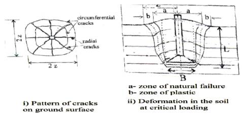
Figure 1. Failure of anchor block foundation in cohesive soil (Kananyan, 1963)
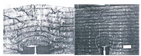
Figure 2. Deformation and Cracking at Ultimate Uplift Resistance for Anchors in Clays (Sutherland, 1988)
In view of the above, a scheme of conceptual failure for underreamed piled deep anchor in clay is formulated for mathematical formulation of failure pullout resistance. The pile-soil system under consideration is shown in Figure 3. It is realized that on application of a pulling force P, a pressure intensity q (assumed to be uniform) acts on XY plane over the rigid base area of diameter Db in vertical upward direction.
For the load of any type acting in vertical downward direction on soil (considering it as weightless elastic medium), Boussinesq's theory gives the induced vertical stress in soil mass at any point. This theory is assumed to be valid for load in soil mass acting in upward direction. As such, for a rigid circular area of diameter Db subjected to upward pressure q at XY plane, the stressed soil zone for an isobar of 10% of q can be plotted as shown in Figure 3. This pressure bulb extends to a height of 1.9Dbabove XY plane. However, the stresses above midplane are of very small magnitude and it is the lower half of the pressure bulb (assumed to be of thickness 0.9Db) where the stresses are significant which may lead to soil failure at ultimate stage. As the pile gradually moves up, with increasing applied load on pile, a small cylindrical cavity beneath the pile is formed at ultimate equilibrium stage. At this stage, full shearing resistance is developed over the idealized cylindrical soil surface shown by ABCD, and the pile tends to plough in soil and the pile thus continues to move up at a larger rate creating larger and larger cylindrical cavity accompanied by plastic flow of soil in the cylindrical zone ABCD in various directions as shown in Figure 4.
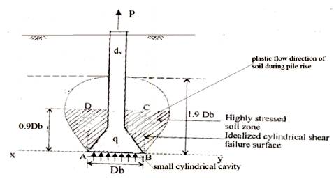
Figure 3. State of Stresses in Soil Above Enlarged Base
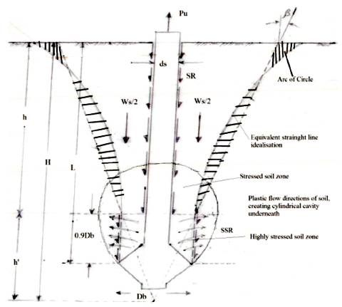
Figure 4. Conceptual Failure Mechanisms and Development of Resisting Forces
Patil (2006) observed the features of underreamed anchor pile behavior and it was found that for larger L/Db ratios of pile, there was apparently no noticeable upheaval of soil surface around the pile. Also, the soil surface, even at ultimate pulling force associated with pile rise of about 3 to 5 percent shaft diameter, remained uncracked. It is therefore assumed that within the soil zone of thickness (L-0.9Db ) below soil surface, there is relative movement between the pile and the surrounding soil effecting mobilization of shaft resistance (SR) commonly referred to as skin frictional resistance. Thus, at the critical or failure stage, the two main components of resisting forces are;
The failure thus remains localized within the small soil zone lying above the base level.
Besides the above described two resisting forces, the effect of the presence of soil mass lying above CD circular area needs to be considered. The soil body whose weight exerts vertical pressure on CD circular surface is not the soil cylinder above CD plane, but it is assumed to be contained within the curved surface above CD plane. The curved surface is considered to be an arc of a circle that originates vertically from CD level and intersecting the ground surface at an angle of 450. The gross ultimate pullout load (Pu ) at the failure stage is thus expressed as;
The net ultimate pullout capacity Pu(net) is therefore,

The soil shear resistance (SSR) evidently equals shear strength of clay multiplied by the vertical surface area of cylinder of diameter Db and height 0.9Db . Thus,
where, cu = undrained cohesion of soil
The shaft resistance (SR) is obtained likewise as the product of skin frictional resistance of pile and the area of shaft surface over its length (L-0.9Db ). Hence,
where, α= shaft adhesion factor
Determination of the weight of soil body with curved boundary surface lying over CD circular area is complex and tedious, though not impossible. Hence an idealization is made by assuming equivalent plane boundary surface for the curved one. This is done in such a way that the volume of body remains unchanged. Such a surface generating line in 2-D figure is to be located so that the volume of revolution of positive area between the curved and straight lines will be almost same as volume of revolution of negative area shown hatched in Figure 4.This exercise was done for several geometrical forms of the soil-foundation system. It was found that the angle β made by straight line with vertical, varied from 220 to 240 .
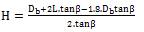
Referring to Figure 4, the volume of inverted frustum of cone of height (L-0.9Db ) is determined by subtracting the volume of cone of height h' from the volume of cone of height H. The computation led to the following equation for weight of the required soil body (Ws);
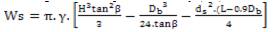
where
Substituting Equations 3, 4 and 5 in Equation 1, the net capacity at failure of underreamed pile anchor foundation is given by,

where H is given by Equation 6.
It is suggested that the value of β be taken as,
For the axially loaded underreamed pile in clay of medium to soft consistency, the value of adhesion factor α is 0.5 as recommended by IS code of practice. In the case of the pullout load on this pile also, the same value of α can be taken.
Black cotton soils from nearby field of Nagpur city was used in the model studies. Its properties were; WL = 59%, WP = 24%, IP =35% and minus 75μ fraction =87%. It belonged to swelling CH category.
The underreamed pile models were prepared from M.S. pipe fitted with circular M.S. plate. The bulb shape was made by cement-sand mortar filling. The shaft surface of model piles was coated with thin film of rich cement-sand mortar to simulate the surface characteristics of actual concrete underreamed pile used in field. Models of shaft diameter 2.2, 3.1 and 6.3 cm were used. For each shaft size four L/Db ratios were used which were 1.5, 3.0, 4.5 and 6.0. The Db /ds ratio of 2.5 was kept for all model piles.
The pile-soil test model was prepared in test drum made from perforated steel sheet. Two test drums of size, (i) 60cm dia. and 60cm ht. and (ii) 25cm dia. and 31cm ht. were used. The saturation tank was constructed of brick masonry wall with firm level bottom. It was provided with drainage pipe at the bottom for draining water from the tank. Pulling load was applied through lever arrangement as shown in Figure 5.
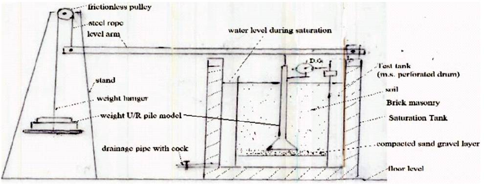
Figure 5. Experimental Setup
Wet soil at water content nearer to its plastic limit was compacted in test drum after placing the model pile in its required position. The drum was kept in saturation tank filled with water. Water was drained out after seven days. The assembly and arrangements were made for loading and pile displacement. It was ensured through meticulous control, to obtain almost identical physical state of soil in all the model tests. The saturated soil during pullout tests 3 had bulk unit weight of 1.72 gm/cm3 and water content at 34%. The loading was done by step loading procedure. UCS tests were carried out on samples collected from unaffected zone of soil in tank after completion of load test. The undrained cohesion cu of soil was found to be 0.24 kg/cm2 .
The pull-rise curves for all the eleven model tests were plotted from the test data. The curves for typical six tests are shown in Figure 6. For all the cases, it was observed in general that, on increasing the pullout load, the rise of pile increases initially at a very small rate and after a certain threshold load, the pile rise increases at faster rate. After a certain critical stage of loading, the pile continues to move up resulting eventually in its extraction. It was also observed that under a pull even slightly smaller than the critical pull causing 'failure' of soil-anchor system, the rise of pile is relatively very small of the order of 3 to 4 percent of pile diameter. Apparently no significant upheaval of the soil surface around the pile and no formation of cracks of any pattern were seen at such a stage of pulling
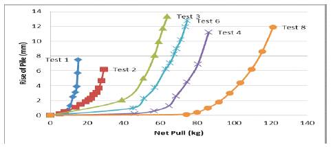
Figure 6. Observed Pull Rise Curve from Some Model Tests
Locating a point on curve characterizing 'failure' of the system was difficult. It was therefore done by 3 procedures; (i) locating the point of maximum curvature by best judgment, (ii) by intersection of two straight lines representing the initial and the later points of curve and (iii) using log-log plot. By giving appropriate weightages to all the procedures, the failure point F was fixed on the curve which gave Pu(net) value. These experimentally observed values for all the eleven tests are shown in Table 2.
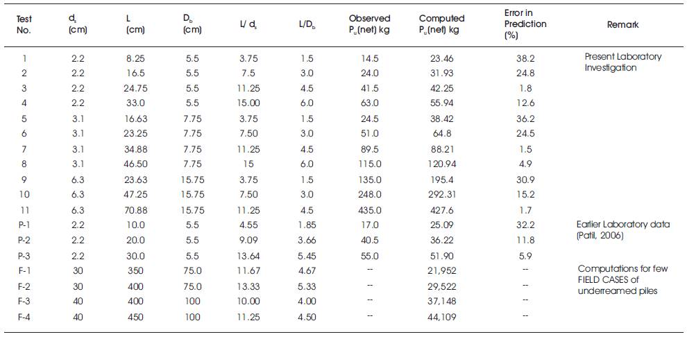
Table 2. Summary of the results of experimental and analytical study
The computed values of Pu(net) were obtained for eleven models used in the laboratory investigation by using appropriate values of α, β, γ and cu. These values are shown in column 8 of Table 2. Computations for earlier data (Patil, 2006) are also given in the table. Error analysis was carried out and results are presented in Figure 7. It is seen that error is less than 15% for underreamed anchor piles having L/ds ratio larger than 8 (i.e. L/Db >3.2). It is larger than 15%, even of the order of 35-40%, for smaller and smaller L/ds ratio than 8. Evidently, such piles may act as shallow anchor for which the proposed failure mechanism explained in the present study will not hold good. However, it is to be realized that the underreamed piles in the field are usually constructed with L/ds ratio larger than 8. Table 2 also includes the Pu(net) values computed from Equation 7 for typical four cases of underreamed piles usually constructed in the field (i.e. piles with L/ds ≥ 10). The computations indicate the net pulling load at failure as 22 tonne for 3.5m long underreamed pile of shaft diameter of 30cm; and 44 tonne for 4m long pile of 40cm shaft diameter. Their safe pullout load may be predicted as 7.5t and 15t respectively. This appears to be reasonable.
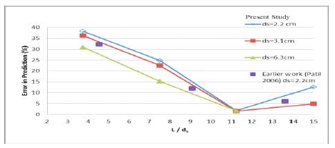
Figure 7. Error Analysis of Test Results
The analysis and experimental studies carried out on underreamed pile to act as a deep anchor foundation led to the following conclusions: