Table 1. Specifications of Slab
A structure consists of the load carrying members which transfer the superimposed load to the foundations below. Its proper function must be served during its life. But the deterioration starts with some passage of time in case of RC structures. Various factors are responsible for this i.e environmental factors, loads, fire, and earthquake and so on. The concept of structure health monitoring and strengthening of structures is a major step towards well being of any structural system and its intended performance under various loads. Ferrocement have been widely used in various forms as structural element. In the present paper, feasibility of using ferrocement is assessed for strengthening of a deteriorated RC two way slab. Rebound hammer and ultrasonic pulse velocity tests were conduced to assess the degree of deterioration. Results were presented in the form of load-deflection response of the slabs along with crack pattern of the slab at various stage of loading. Results are found to be in well agreement with those obtained from analytical investigations.
The deterioration of structures poses a complex problem and need continuous inspection of structures. Structural Health Monitoring is an area that is receiving tremendous attention so as to have an efficient utilization of structure throughout its life span.
Ferrocement as a construction material has gained acceptance in different applications namely housing, canal-lining, nining material over cement concrete, brick masonry and so on. Ferro cement is a composite material mainly consisting of a cement matrix along with a mesh, which may be of any economically available material satisfying certain conditions such as steel, bamboo and so on. Because the diameter of mesh is much smaller than that used in Reinforced cement concrete, it provides comparatively higher surface area per unit volume and as a result much improved tensile strength Due to high bond strength existing between cement matrix and mesh, failure of Ferro cement in tension generally takes place by yielding of mesh wires; not by pullout from mortar, thus improves the ductility and post cracking behaviour. (Thesis page 2). Ferro cement can be considered as a special form of reinforced concrete; however it exhibits behaviour so different from conventional reinforced concrete in performance, strength and application that makes it a separate material.
Tests conducted by Hashemi and Mahaidi (2010) have shown that excellent bonding properties can be achieved using the cement based adhesives. Tests include the investigation of bond strength of FRP fabrics and flexural behavior of FRP strengthened reinforced concrete beam using cement based adhesives. The specimens were 245×75×75mm3 concrete prisms. The surface of the specimen was sand blasted to achieve a high level of bonding between mortar and concrete. CFRP material was applied in two different shapes including fabric and textile, with equal cross section area of CFRP. The tests had been performed on specimens having different bond lengths. This included 100mm and 180mm bond lengths with and without end anchorage. The tests showed that the mortar performed adequately as bonding agent in all samples. The anchored prisms showed higher levels of load carrying capacity compared to the unanchored ones.
One beam was retrofitted with 2 strips of CFRP fabric using normal epoxy adhesive. The failure was characterised by a combination of mid-span and end debond. The load carrying capacity was P=161.7 kN, which is 35% higher than the control beam capacity. Cementitious mortar adhesive was used to attach 2 layers of CFRP fabric strips to the soffit. Four point bending was done and as the load was progressively increased, a flexural shear crack developed near the point load.
As the load was further increased, most of the fabric was debonded on one side of the beam and the beam started to exhibit a response similar to that of the control beam. The load carrying capacity was P=132.1 kN, which is 10% higher than the control beam capacity. The ultimate load which was achieved by using CFRP textile-cement mortar is around 80% of what was achieved by using CFRP fabric with epoxy adhesive.
In recent years, the use of externally bonded fibre-reinforced polymers (FRP) has become increasingly popular for civil infrastructure applications, including wrapping of concrete columns. Significant research has been devoted to circular columns retrofitted with FRP and numerous models were proposed. The use of externally bonded FRP composite for strengthening and repair can be a cost-effective alternative for restoring or upgrading the performance of existing concrete columns. Even though a lot of research has been directed towards circular columns, relatively less work has been performed on square and rectangular columns, to examine the effects of external confinement on the structural performance. However, the vast majority of all columns in buildings are rectangular columns. Therefore their strength and rehabilitation need to be given attention to preserve the integrity of building infrastructure. The paper proposed by Kumutha et.al (2007) is directed towards this endeavor. Totally nine reinforced concrete columns were tested under concentric compression in testing frame. The columns were cast horizontally in steel forms and compacted using a needle vibrator. The length (750 mm) and the cross-sectional area (15625 mm2) were kept constant for all the specimens. Each specimen had middle test region 750 mm long and two enlarged capitals at their ends. The capital of height 160 mm was provided at both ends of the columns to distribute the load evenly. This configuration serves to stabilise the column during testing. All columns had longitudinal reinforcement consisting of 4 deformed bars, 10 mm in diameter with yield strength fy = 477.5 N/mm2 and ultimate strength fu = 603.5 N/mm2. All specimens were loaded until failure under axial compression in a testing frame. All the nine columns were tested under similar conditions. Longitudinal and transverse strains were manually measured using DEMEC gauge with 100 mm gage lengths having a least count of 0.002 mm. Pellets were glued either on the concrete surface for control specimens or on the GFRP outer layer for strengthened specimens. Pellets were fixed at mid height of the column for strain measurements in both longitudinal and transverse direction. From the results, it can be seen that, the confinement of columns with GFRP wrap increases load carrying capacity of reinforced concrete columns. In addition, the greater the number of GFRP layers, the greater the gain in axial load carrying capacity with respect to unconfined columns. Local buckling of longitudinal reinforcement was observed in the unwrapped columns. For most wrapped columns, the failure was associated with concrete crushing at or near the column ends and marked by wraps rupturing in the circumferential direction. After failure the concrete was found S disintegrated. Failure of GFRP wraps was observed at or near a corner in all the specimens mainly due to stress concentrations. This may be expected since column's sharp edges were not rounded off. In order to avoid stress concentration, attempt should be made to round off sharp corners. The ultimate load predicted from the proposed analytical model was compared with the experimental results as shown in Table 2. It was found that a good correlation was obtained between the experimental results and those got from the theoretical model. The maximum error was found to be only less than 7%.
Effective confinement with GFRP composite sheets resulted in improving the compressive strength. Better confinement was achieved when the number of layers of GFRP wrap was increased, resulting in enhanced load carrying capacity of the column, in addition to the improvement of the ductility. The load carrying capacity of the column decreased, with increase in aspect ratio of the cross-section. The test results show a clear overall linear relationship between the strength of confined concrete and lateral confining pressure provided by FRP. Based on the analysis of the experimental results, a simple model has been proposed for the prediction of the ultimate load of FRP confined columns, and a good correlation was obtained between experimental and analytical results.
In the study reported by Yang et.al (2009), a total of 13 FRP-strengthened reinforced concrete beams were tested in flexure and analyzed using the finite element method. The various variables included bonding or no bonding of the FRP, the anchorage system, the amount of prestressing, and the span length. The experiments consisted of one control beam, two non-prestressed FRP-bonded beams, four prestressed FRP-unbonded beams, four prestressed FRP-bonded beams, and two prestressed FRP-unbonded beams with different span lengths. All the beams were subjected to three-point and four-point bending tests under deflection control, with the loading, deflection and failure modes recorded to the point of failure. A nonlinear finite element analysis of the tested beams was also performed using the DIANA software; this analysis accounted for the nonlinear concrete material behaviour, the reinforcement, and an interfacial bond-slip model between the concrete and CFRP plates. The aim of this investigation was to study the flexural performance of reinforced concrete members strengthened using CFRP plates, employing different FRP bonding and prestressing methods. The failure mode of the prestressed CFRP-plated beams was not debonding, but FRP rupture. For the reinforced concrete members strengthened with externally bonded prestressed CFRP plates, debonding of the composite laminates occurred in two stages. After the debonding of the CFRP plates that occurred in the bonded cases, the behaviour of the bonded CFRP-plated beams changed to that of the unbounded CFRP-plated beams due to the effect of the anchorage system. The flexural test results and analytical predictions for the CFRP-strengthened beams were compared and showed very good agreement in terms of the debonding load, yield load, and ultimate load. The ductility of the beams strengthened with CFRP plates having the anchorage system was considered high if the ductility index was above 3.
The paper reported by Mukherjee et.al (2009) presents the result of experimental study to investigate the flexural behaviour of reinforced concrete beams that have reached their ultimate bearing capacities and then retrofitted with externally prestressed carbon fiber reinforced composite laminates. The effect of variation in prestressing force on CFRC laminates bonded to RC beam is investigated in terms of flexural strength, deflection, cracking behaviour and failure modes. The results indicate that rehabilitation of significantly cracked beams by bonding CFRC laminates is structurally efficient.
The potential use of mechanically-anchored unbonded fibre reinforced polymer (MA-UFRP) system to upgrade reinforced concrete (RC) slabs deficient in flexural strength was examined by Maaddawy (2008). A total of six RC slabs, each having 500 mm width, 100 mm thickness, and 1800 mm length, were constructed and tested to failure under four-point bending. Each slab was reinforced with three No. 10 deformed steel bars at tension side that corresponded to 0.8% steel reinforcement ratio. One slab was used as a control while the other five slabs were strengthened with various fibre reinforced polymer (FRP) strengthening systems, each having 0.12% external FRP reinforcement ratios. Two slabs were strengthened with externally-bonded FRP (EB-FRP) system, one slab with end-anchorage and one slab without end-anchorage. The remaining three slabs were strengthened with MA-UFRP system having various anchors' locations. Test results showed that MA-UFRP system resulted in up to 43% enhancement in the slab flexural strength. The strength of the slabs strengthened with MA-UFRP system was on average 18% lower than that of the slab strengthened with EB-FRP system with end anchorage but only 10% lower than that of the slab strengthened with EB-FRP system without end-anchorage. The mid-span deflection at ultimate load of the slabs strengthened with MA-UFRP system was on average 56% higher than that of the slab strengthened with EBFRP without end-anchorage, 5% higher than that of the slab strengthened with EB-FRP with end-anchorage, and only 15% lower than that of the control.
The results of punching shear tests on 31 square Ferro cement slabs are reported by Mansur et. al (2001). The slabs were simply supported on all four sides and tested under a central concentrated load. The parameters investigated include the width of square loaded area w, mortar strength , volume fraction of reinforcement Vf, depth of slab h, and the effective span . All slabs failed first in punching without total separation, and then exhibited a second peak in the load-deflection history. Both cracking load and punching shear load increased with an increase in w, Vf, or h. The critical perimeter for punching shear f9c failure was found to be located at a distance of 1.5h from the edge of the loading plate. Based on the present test data as well as those available in the literature, an equation has been proposed for predicting the punching shear strength of Ferro cement.
The results of an experimental study of the feasibility of strengthening deficient RC cantilever slabs were presented by Teng et.al (2000) by bonding glass FRP (GFRP) strips/sheets on the top surface (the tension side). As the key to the success of this strengthening method is a proper way of anchoring the GFRP strips into the supporting wall and the slab, the effectiveness of different anchorage systems was the focus of the experiments. Based on the test results, a simple and effective method is identified in which the GFRP strips are anchored into the walls through horizontal slots and onto the slab using fiber anchors.
The paper reported by Aboul-Anen et.al (2009) presents the experimental models of Ferro cement slabs with and without steel sheeting and their numerical models using the finite element method. Finite element models were developed to simulate the behavior of the slab through nonlinear response and up to failure, using the ANSYS Package. Additionally, the comparison between the theoretical and experimental models is presented and discussed experimental models of Ferro cement slab with and without steel sheeting and their numerical models using the finite element method will be presented. Finite element models are developed to simulate the behavior of the slab through nonlinear response and up to failure, using the ANSYS. The ANSYS model accommodates material non-linearities, cracking and crushing of concrete (or mortar) and yielding of the steel sheeting and wiring meshes. The analytical results compared well with the experimental for the Ferro cement slabs without steel sheeting. The analytical results compared well with the experimental for the Ferro cement slabs without steel sheeting. For those specimens with steel sheeting, the comparison was good until the failure of the bond between the slabs and the steel sheeting.
The investigation by Shayma'a A. Mohammed(2011) focused on the composite action of the Ferro cement slabs and steel sheets. The experimental models of Ferro cement slabs with and without steel sheeting and their numerical models using the finite element method will be presented. Finite element models are enveloped to simulate the behavior of the slab through nonlinear response and up to failure, using the ANSYS. The spherical of simply supported slabs with 500x500x20mm (with vertical diameter 60mm high) and 0.7mm wire mesh were selected for the analysis using the finite element software ANSYS. The slabs were reinforced with three percent of reinforcement using two, four and six layers of wire mesh. The supports were applied at 400x400mm and the corner edges were restrained from any movement. The thickness of the slab change from 20 to 40 mm, the vertical diameter change from 60 to 70 mm with and the horizontal diameter change from 500 to 600mm with constant thickness. The results show an increase in the ultimate load values with the increase of wire mesh layers. The increase in number of wire mesh from 2 to 4 with distributed loads shows an increase in the ultimate capacity by about 18.3% and from 2 to 6 indicates an increase of 28.2%. The load carrying capacity of the tested Ferro cement members are close to with predicted in the proposed finite element analysis. Finite element method can be adapted to the analysis and design of Ferro cement slabs.
Different applications of Fiber Reinforced Polymer Composites (FRPCs) for external strengthening in civil construction are reviewed by Pendhari et.al (2008). Experimental as well as analytical and numerical research contributions have been focussed in the review. The main structural components such as beams, columns and beam-column joints, have been reviewed and structural behavior of each component is discussed briefly. The main objectives of the paper are to classify the available literature (analytical/experimental) and to discuss the effects of various parameters such as fiber type, thickness, fiber angle, concrete strength, etc. Use of FRPC improves load carrying capacity and energy absorption capability of slabs reinforced with FRPC. Studies have demonstrated improvement in ultimate capacity and stiffness leading to reduction in the overall maximum deflection and strains. General cohesiveness, stress transfer capability across the crack improves due to strengthening, which delays crack formation and thus FRPC reinforcement is able to achieve its full potential of strengthening of slabs.
Much research has been conducted on the use of FRP Strengthening of structural members on slabs, columns, joints that may include behaviour of crack pattern, failure criterion, health monitoring etc. However, its importance is increased when the investigation make a move towards study on health monitoring of slabs before retrofitting and after retrofitting the slab with Ferro cement. This paper describes an investigation on this topic.
The use of superficially bonded FRP composite for strengthening and repair can be a cost-effective alternative for restoring or upgrading the performance of existing concrete columns. Even though a lot of research has been directed towards columns, slab-column joints; relatively less work has been performed on slabs, to examine the effects of external reinforcement on the structural performance. Their strength and rehabilitation need to be given attention to preserve the integrity of building infrastructure. This paper is directed towards this endeavour.
Cement, fine aggregates, coarse aggregates, reinforcing bars are used in casting of slabs. Wire mesh is used as a retrofitting material in slabs.
Ordinary locally available Portland cement having a specific gravity of 3.15 was made use of, in the casting of the specimens.
Ghaggar or Pathankot sand having a fineness modulus of 2.54, and a specific gravity of 2.62 was used in the experimental investigations.
Crushed granite coarse aggregate of 10 mm maximum size having a fineness modulus of 7.94 and specific gravity of 2.94 was used.
Design Concrete Mix M-20 was used for casting of slabs.
HYSD bars of 8mm diameter were used as reinforcement
It is proposed to take the two-way slab supported over the rigid boundary. The slab is specified in tabular form in table 1 as under
GI woven mesh with square grid was used for ferro cement. The grid size of mesh was (18x18) mm. The properties of mesh wires are listed in Table 2 as under.
Table 1. Specifications of Slab
Table 2. Properties of wire mesh
The main aim of investigation was to study the behavior of rectangular slab before and after retrofitting with Ferro cement. For this experimental investigation, two size of slabs; S1 (2350 x 1750 x75)mm and S2(2350 x 1566 x 75)mm and M-20 mix was used. Three slabs of each size were casted for testing.
Therefore, a total of six slabs; three of each size (S11,S12,S13) and (S21,S22 and S23) were cast and tested before retrofitting and after retrofitting with Ferro cement.
For conducting Health monitoring of slabs, two NDT techniques i.e. Rebound Hammer Test and Ultrasonic Pulse velocity Test were performed. The NDT was carried out before and after retrofitting.
First of all, six frames; three for each size of slab; were made. Then casting of slabs was done. The slabs were Reinforced using HYSD bars of 8mm diameter and it was laid at the bottom cover of 15mm and side cover of 25mm. Proper compaction was done with the help of needle vibrator. The surface was finished and the slabs were kept as such for 24 hours and then cured for 28 days.
Reaction Frame was used in the Heavy Testing lab of civil engineering department of the college. The simply supported slabs were lifted inside the lab with the help of arrangement that consisted of steel frame fitted with hooks to lift the slab. It is also provided with wheels that carry the slab inside the lab and place it at the required position. Then NDT and loading was done. Point load is applied and it is converted into uniformly distributed load with the help of steel balls. The deflection was obtained with the help of dial gauge placed at the bottom central position of the slab.
First of all, NDT was carried out and Structural Health Monitoring of the slabs was done by Rebound hammer Test and the Ultrasonic Pulse Velocity Test. To conduct these tests, points at an equal distance of 40cm were marked both at the top and the bottom surface of the slab.
To conduct Rebound Hammer test at these points, Digital Rebound Hammer was used and the reading was noted by keeping the hammer in vertical position at the top surface of the slab as shown in Figure1. This value was then checked against the strength of mix.
For Ultrasonic Pulse Velocity Testing, the testing was done by keeping the transmitter and the receiver at these points at the top and the bottom surface of the slab. The reading on the machine as shown in Figure 2 gave the value of time (in microseconds) taken by the waves to travel through the thickness of the slab. This reading was then converted into the velocity of waves and then checked for the quality of concrete against the standard values.
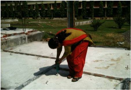
Figure 1. Rebound Hammer Test
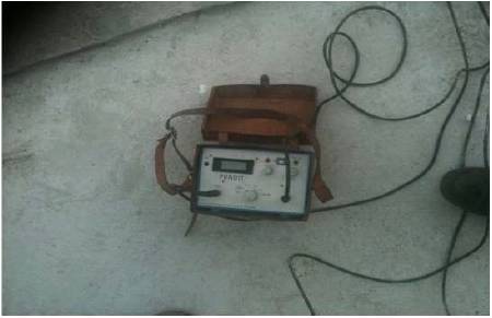
Figure 2. Ultrasonic Pulse Velocity Test machine
For Retrofitting, wire mesh was used at the tension face of the slabs as shown in Figure 3.First of all. cement-mortar was laid at the bottom face of the slab. Then layer of wire mesh was placed as shown in Figure 4. Then, again cement mortar mix was laid. Needle-vibrator was used for thorough compaction. The slabs were then cured for 28 days.
Thereafter, the reading by Rebound Hammer test and Ultrasonic Pulse Velocity Test were taken. After that, the udl was applied to the slab and testing was done. Load-deflection curves were drawn and results were interpreted.
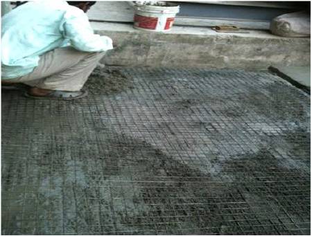
Figure 3. Ferrocement for Retrofitting
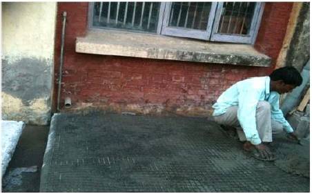
Figure 4. Placing of Ferrocement
The Reaction Frame was used for the testing of the slabs. The slabs were tested under uniformly distributed load and the deflection was recorded by dial gauge. The slabs were loaded till the cracks spread throughout the surface of the slab. Then these cracks were filled by pressure grouting and retrofitting was done by ferro cement.
The readings of NDT carried out on the two slabs are tabulated as under in Table 3.
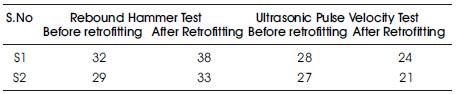
Table 3. NDT values at centre of the slab
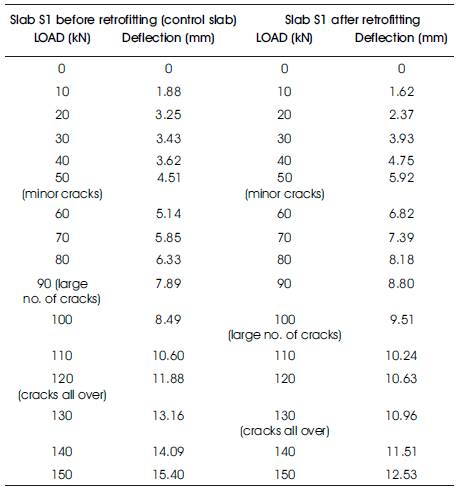
Table 4. Load-Deflection values for slab S1 before and after retrofitting
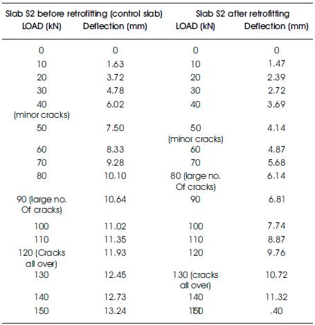
Table 5. Load-Deflection values for slab S2 before and after retrofitting
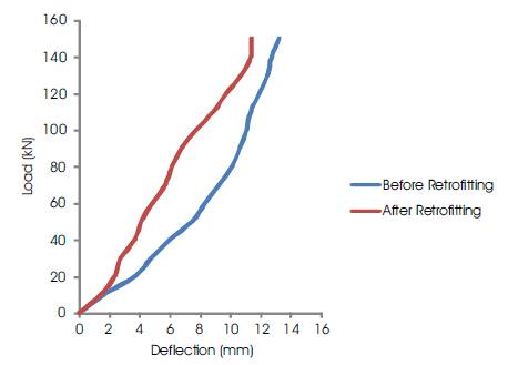
Graph 1. Load-Deflection curve of slab S1
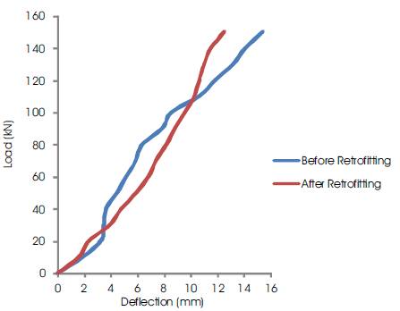
Graph 2. Load-Deflection curve of slab S2
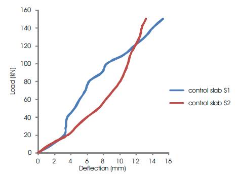
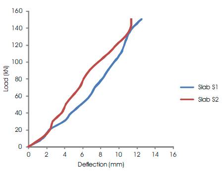
Graph 3. Load-Deflection curve of control slabs S1 and S2
Graph 4. Load-Deflection curve of retrofitted slab S1 and S2
The numerical applications on ferro cement members using the finite element analysis are carried out to investigate the behavior of ferro cement slabs. Verification is done in order to check the validity and accuracy of these models. The results obtained using finite element models are compared with the experimental results through the load deflection curves.