
Table 1. Specific gravity of materials used for Concrete mix
Cracking is one of the frequent causes of complaints in concrete industry. Cracking is known to occur due to fatigue , overloading and damage caused either by loading or environment. The failure of bridges,structures , buildings and dams is due to cracking. This underlines the importance of estimation of crack width as predictor for the health of concrete structures. The results obtained with a POF ( plastic optical fibre) based local (point) sensor that was developed for use with concrete specimens in a three point bend test for in house experiments are reported. The range of CMOD ( Crack mouth opening displacements ) values are established.
Many public structures that are well designed need periodic maintenance and regular inspection to ensure their health. In this connection crack monitoring and detection plays an important role. Crack widths ranging from 0,2 mm to 2.0 mm caused either by exposure to environment, natural hazards are known to signal the failure of the structure. In this context both non optical and optical methods have been cited in literature for the purpose of crack detection (Hong-Nan Li, Dong Sheng Li, Gang-Bing Song, 2004).These include i) ultrasonic ii) Acoustic emission iii) Impact- Echo iv) Infrared –red Thermography v) Ground penetrating radar vi) Moire Interferometry vii) Holographic and speckle interferometric methods –these tell only the presence of the crack but do not provide information on crack opening . Furthur they are incapable of continuous real time remote sensing.
The variety of optical fibre based sensors in vogue include: Fibre Bragg Gratings (Mousumi Majumder, Tarun Kumar Gangopadhyay, Ashim Kumar Chakraborty, Kamal Dasgupta , &. Bhattacharya, (2008) ), intensity based , polarimetric –type sensors and sensors based on principles of standard interfereometers (Fabry-Perot, Mach-Zehender) etc.for specific application areas. (Kuang, Quek , Koh,. Cantwell , &. Scully, (2009 ))
The fibre optic sensors in particular for use in civil engineering applications can also be classified as i) local(point), ii)quasi distributed and iii) distributed sensors based on their range of sensing (Hong-Nan Li et.al). However the excellent performance of these methods (especially the optical methods) is offset by their expensive instrumentation requirements for signal processing. In most cases the high measurement resolution provided by these methods proves to be of no direct advantage given the fact that more economical methods are provided by using plastic optical fibres. Also the intensity based devices are of low cost, and it is easier to measure the optical power than the phase/state of polarization of light. It is more advantageous with multimode fibres as the phase and state of polarization is lost when it propagates through this kind of fibres.
It is necessary to choose an economical and inexpensive technique that would fit into present needs in the long run. Hence the use of plastic optical fibres for the investigation of crack width experiments in concrete members has been adopted in this investigation.
Plastic optical fibres are now currently used for measurement of several physical parameters as strain, displacement force, pressure etc., in a variety of materials ranging from composites to concrete and other traditional materials. They are offer all the advantages that are already known to offer by silica based optical fibres. The other attractive advantages include: a) capable either of being surface mounted or be embedded in large civil structures and composite materials to asses their reliability b) large inherent strain sensitivity (6%-12%) c) have high fracture toughness d ) provide large core size, large numerical aperture, flexibility, easy handling, less costly. (Kuang, et.al., Mousumi Majumder, et.al , Zubia, & Arrue, (2001)).
Cement conforming to IS 12269 – 1983 with specific gravity 3.15 is used for the concrete mix. Natural river sand with specific gravity 2.60 is used as fine aggregate. Crushed coarse aggregate of size 20mm was used (60%) and also 10 mm size was used (40%) with specific gravity 2.78.The details of materials are tabulated in Table 1.
M20 grade concrete mix design was used for the casting and the mix ratio: 1:1.58:3.17 was used for the preparation of concrete samples (Subhash Chander , (1995–96) , Muralidhara Rao. (2010) ).
Cubes of 100mm size were used to determine the compressive strength of concrete. Cylinders with 150 mm diameter and 300 mm length were used to determine the Modulus of Elasticity of concrete. The modulus elasticity of the concrete is found to be 28,560MPa. Prisms of 400mm x100mm x 100mm (L x B x D) , beams of dimensions 700X 500 X 100 (L x B x D), size were cast. (refer Table 2) A needle vibrator was used for compaction. All the specimens were cured for 28 to 40 days in the curing tank. After curing time the samples were separated from the curing tank and notch depth (a/d=0.2, 0.3) was used for the prisms and beams. Notch was made in the specimens using notch cutter.

Table 1. Specific gravity of materials used for Concrete mix

Table 2. Composition of the Concrete Members
The optical sensor was a standard multi-mode plastic optical fibre (POF) (having a core diameter of 980 µm made with PMMA resin surrounded by a fluorinated polymer cladding of diameter 1000 µm). A LED source is used to inject a modulated light beam into the plastic optic fibre whose light output is received by a highly-sensitive NPN phototransistor. The photo transistor's current is converted to voltage using a transimpedance amplifier. A simple, inexpensive transimpedance amplifier was designed that converts the current generated by the photo transistor in to voltage which is then logged into a computer using a data logger.
The surface of the POF sensor was abraded using a fresh blade causing the removal of a predetermined length of the cross section. (we refer to this as guage/ sensitization length , approximate range = 2 to 5 cm). This process of abrasion increases the amount of light lost in the fibre during its bending process resulting in better accuracy. The sensor so prepared is glued to a pre-notched concrete specimen, where the crack mouth opening displacement is to be measured. Cyanoacrylate adhesive is generally used to glue the POF to the concrete surface (Kuang, Akmaluddin, Cantwell., & Thomas, (2003)) and the same adhesive is used in the present investigation also. Figure (1c ) shows a photograph of the plastic optical fibre sensor pasted across the pre notch of the concrete member.
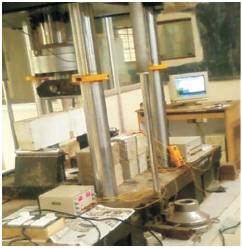
Figure 1 (a). Experimental Setup for the Three point bend test of Concrete Beam on 1000KN Instron
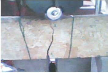
Figure 1 (b). Photograph showing the Development of the Crack in the Prenotched Specimen
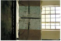
Figure 1 ( c). Photograph Showing the POF Sensor the Prenotched Mounted Across the Prenotch Region of the Concrete Member
Figure (1a) shows the experimental set up adopted for the 3-point bend specimen test arrangement in the Materials Laboratory of the Civil Engineering Department, at NIT, Warangal.
Figure (1 b) illustrates the development of crack across a loaded member The three point bend tests were performed on five concrete beams with dimensions (40*10*10) cm, (70*15*10) cm using INSTRON. The load was applied on the beam with a cross head displacement rate of 0.002 mm per sec. During the loading the data obtained from the POF sensor was logged using a data logger with a sampling speed of 1 sample/ sec typically. Figure 2 shows the typical variation of normalised POF, load (KN) with displacement of the cross head i.e., stroke (mm) for three members 1,2,3. Stroke is the displacement of concrete beam in the vertical direction at mid span, where the member is pre-notched. The crack mouth opening displacement is related with the stoke (δ) as,
Figure 2. Typical Plots between Stroke (mm)v/s norm.pof voltage/Load (kN) for concrete member 1, Concrete Member 2, and Concrete Member 3
The above data is fitted into the relation between stroke and CMOD given below (Testing sprayed concrete: EFNARC ( 2011) ).
Crack opening = 4xδx (0.9xh)/span
CMOD = 4xδx(0.9xh + notch depth)/span
where
δ is the deflection, in millimetres;
CMOD is in millimetres,
h is the unnotched height of the specimen in mm
Figures 3 (a), 4(a), 5(a) depict the plot of the data fitted to the above formula (CMOD) respectively Figures 3 (b), 4 (b) and 5 (b) illustrate the combined plot of CMOD vs normalised POF intensity, load (KN) redrawn. The POF intensity is observed to vary with stroke, which is related to the crack mouth opening displacement (CMOD).
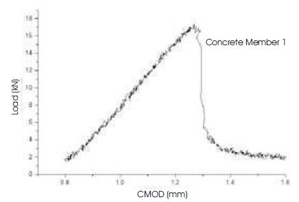
Figure 3 (a). Fitting to CMOD formula for member 1
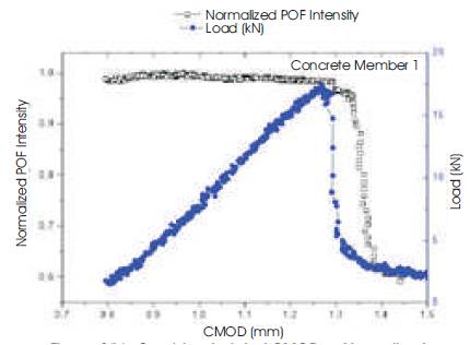
Figure 3(b). Combined plot of CMOD vs Normalised POFIintensity/Load (KN)
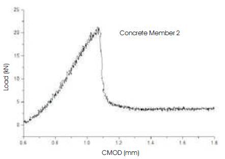
Figure 4 (a). Fitting to CMOD formula for member 2
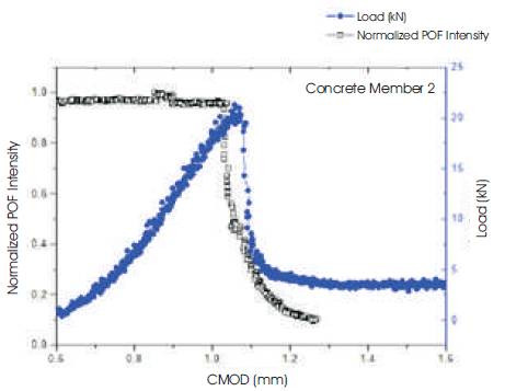
Figure 4(b). Combined plot of CMOD vs Normalised POF Intensity/Load (KN)

Figure 5. Fitting to CMOD Formula for Member 3
During the initial stages of loading the member is elastic and curvature is quite large, with very small deflections. This results in very little variation of light intensity from plastic optical fibre. With the increase in the applied load there is loss of light from the POF's sensitized zone – this is caused due to reduction in the number of propagating modes within the fibre leading to reduction in intensity. Significant reduction in light intensity is observed when the pre notched crack starts to grow beyond the peak load. This is attributed to reduced stiffness (this can be observed from the load- stroke response of the member) of the beam. This indicates that the drop in POF voltage is an indicator of crack formation or crack propagation of the member. Hence from Figures 3 (a), 4 (a), and 5 (a) a sudden drop in load stroke response of the member indicated a sudden failure of the beam with crack extended from the tip of thenotch to the load point. The CMOD is presented in Figure 3 (b) 4 (b), respectively for the three members. From this variation, it can be stated that a sudden drop in POF indicated a growth in the crack extension. The present test results are only preliminary in nature and further testing is needed to reinforce the use of optic based sensors for estimating crack opening displacements as well as for health monitoring of the structures.
It can also be concluded that the rate of reduction of light intensity from the plastic optical fibre following crack initiation and development vary from member to member and the reason for such a behaviour lies in the bend sensitivity of the mounted sensor (Kuang, et.al (2003)).
Based on the testing using plastic optical fibres sensors for estimating the crack mouth opening displacement of the pre notched concrete beams, the following conclusion are drawn.