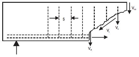
Figure 1. General Mechanism of Shear Resistance in Reinforced Concrete.
A non linear finite element analysis is conducted using ANSYS10 a finite element package on eight high strength concrete beams (M70) varying shear span to depth ratio (a/d=1, 2, 3 and 4) to evaluate shear resistance with and without web reinforcement. The study emphasize on the effect on shear span to depth ratio on shear resistance, the effectiveness of web reinforcement under shear loading and behaviour of high strength concrete beams in pre and post cracking regions with and without web reinforcement. In this course of research eight beams are cast and tested under shear loading for a/d=1, 2, 3 and 4 (two beams for each a/d ratio) with and without web reinforcement, the results indicate the increase in the cracking shear resistance noticeably and ultimate shear strength moderately. The improvement in shear strength of high strength concrete beams with and without shear reinforcement for shear span to depth ratios (a/d = 1, 2, 3 & 4) is significantly established by comparing the experimental results of beams and analytical results evaluated from ANSYS. The results show a good agreement between analytical and experimental data. Finally, the results presented are useful information for development of shear model to predict shear strength of high strength concrete beams.
Utilization of high strength concrete (HSC) in construction sector has increased due to its improved mechanical properties compared to ordinary concrete. With the development of concrete technology and the introduction of superplasticizers and use of pozzolans, the compressive strength of concrete in the field of ready mixed concrete reached 100 MPa and higher. Since the mechanical properties of concrete are changed in high-strength concrete, a reevaluation of the prediction model is necessary to reliably estimate the shear strength of beams made with high-strength concrete. Moreover, because of the wider range of concrete strength used, more accurate predictions of shear strength of reinforced concrete members are required. Therefore shear resistance of concrete beams is an intensive area of research.
To estimate the shear resistance of beams, standard codes and researchers all over world have specified different formulae considering different parameters into consideration. The parameters considered are varying for different codes and researchers leading to disagreement between researchers, making it difficult to choose an appropriate model or code for predicting shear resistance of reinforced concrete. However, an increase in the concrete strength produces an increase in its brittleness and smoothness of shear failure surfaces, leading to some concerns about the application of high strength concrete. Therefore an extensive research work on shear behavior of high strength concrete is being carried out all over the world. The major researchers include Bazant [1], Zsutty, [2] Piotr Paczkowski [3], Jin-Keun [4], Imran [5], and many more. Estimation of shear resistance of high strength concretes is still controversial therefore it's a thrust area for research.
The shear resisting mechanism of reinforced concrete can be qualitatively analyzed upon the behaviors of;
Figure 1. General Mechanism of Shear Resistance in Reinforced Concrete.
Though, it is difficult to quantify each parameter in estimating shear resistance of concrete, many researchers [6 to 12] proposed the model to calculate the shear crack load of reinforced concrete without web reinforcement based on experimental results. The shear strength of reinforced concrete beams with stirrup can be determined by analyzing concrete and stirrup based on 45-degree truss analogy. In the recent past a new concept emerged which emphasized the concrete and stirrup interaction. The interaction enhances the dowel action, because of the support offered by stirrups to longitudinal bars and the strength of concrete both, due to an inclined compression field associated with truss mechanism.
The shear failure of reinforced concrete beams without web reinforcement is a distinctive case of failure which depends on various parameters such as shear span to effective depth ratio (a/d), longitudinal tension steel ratio (ρ), aggregate type, strength of concrete, type of loading, and support conditions, etc. Most of the researchers concluded that failure mode is strongly dependent on the shear span to depth ratios (a/d). Berg [13], Ferguson [14], Taylor [15] found that shear capacity of Reinforced concrete beams varied with a/d ratio. In this research, shear span-to-effective depth ratio is taken as main variable keeping all other parameters constant for the beams with and without web reinforcement.
Fanning [16] evaluated reinforced and post tensioned concrete beams using the ANSYS package. Kotosov [17] analyzed short shear reinforced concrete beams using 3D finite element approach to validate the rational prediction of its behavior observed in the test program. Zho [18] analyzed nonlinear behavior of reinforced concrete deep beams using a 2D finite element method. The present study concentrates on details of the finite element analysis of shear critical high strength rectangular beams with and without web reinforcement. The finite element analysis of the tested beams is carried out in 'ANSYS' package considering perfect bond between the tension, web reinforcement and the surrounding concrete. The predicted results using 'ANSYS' model, have been compared with the corresponding test data.
Sixteen reinforced HSC beams are cast and tested, under two point loading, varying the shear span to effective depth ratio (a/d). The test specimens are divided into two series. Each series consisted of two high strength concrete beams without shear reinforcement with a/d ratio 1, 2, 3 & 4. For all the series, the parameters viz., concrete proportions and percentage of longitudinal steel are kept constant. The details of the beams cast are listed in the Table 1.

Table 1. Reinforced Beams with and without Shear Reinforcement
Ordinary Portland cement whose 28- day compressive strength was 53Mpa was used. Natural river sand confirming with specific gravity 2.65 and fineness modulus 2.33 was used as fine aggregate. Crushed Coarse aggregate of 20mm and 10 mm procured from local crusher grading with specific gravity 2.63 was used. Potable water free from any harmful amounts of oils, alkalis, sugars, salts and organic materials was used for proportioning and curing of concrete.
In the present experimental investigations naphthalene based superplasticizer conplast337 was used for enhancing workability. Further, natural pozzolans such as Class F fly ash(acquired from KTPS, Kothagudam, Andhra Pradesh, India) and Ground Granulated Blast Furnace Slag (procured from Vizag confirming to IS 12089 1987 [19]) were used to enhance strength and workability.
The beams were provided with 16 mm diameter bars as tension reinforcement whose yield strength was 475Mpa and 8 mm diameter bars as shear reinforcement whose yield strength was 500Mpa.
The high strength concrete mix design was done using Erntroy and Shacklock method [20]. By conducting trial mixes and with suitable laboratory adjustments for good slump and strength the following mix proportion was arrived as shown in Table 2.
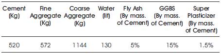
Table 2. Mix Proportion of Concrete
Tests are carried out on sixteen beams, simply supported under two point loading. The beam cross section adopted is 100mm x 150mm, illustrated in Figure 2 (constant for all beams). The length of beam was worked out to be 0.7m, 1.0m, 1.2m and 1.6m for corresponding a/d ratio = 1, 2 , 3 & 4 respectively. The first series of beams ('R' Series) are provided with 3-16 mm diameter HYSD bars as longitudinal reinforcement to avoid any possible failure by flexure. The second series of beams ('SR' Series) are provided with 3-16 mm diameter HYSD bars as longitudinal reinforcement and 8mm diameter bars are provided as shear reinforcement at 100mm c/c. The grade of concrete (M70) is kept constant for all the beams.
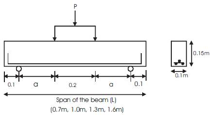
Figure 2. Details of Test Beams (without web reinforcement) with Arrangement of Loads and Supports
The beams are tested under gradually increasing load using a 100 ton loading frame. The beam is simply supported using knife edge support which are placed on two support beams (I sections) shown in Figure 2. The specimen is loaded using a 100 ton jack which has a load cell to monitor the load .The load was transferred from the jack to specimen at two points using a spread beam. Based on the a/d ratio of the support beams on which the simple supports are placed and adjusted. Two LVDT's are provided, one at the centre of the span and other at the centre of the shear span to measure deflections. The load and deflections are monitored for every 5 seconds. The load that produced the diagonal crack and the ultimate shear crack are recorded. Crack patterns are marked on the beam. The average response of two beams tested in a series, is taken as the representative response of the corresponding series. The test set up is presented in Figure.3 and 4.
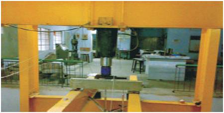
Figure 3. Beam and LVDT Arrangement in 100 ton Loading Frame
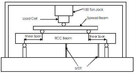
Figure 4. 100 ton Loading Frame with the Test Setup
The finite element method is a numerical analysis technique for obtaining approximate solutions to a wide variety of Engineering problems. ANSYS is a general purpose finite element modeling package for numerically solving a wide variety of problems which include static/dynamic structural analysis (both linear and non-linear), heat transfer and fluid problems, as well as acoustic and electro-magnetic problems. The HSC beams with tensile reinforcement and without shear reinforcement have been analyzed using a finite element (FE) model in ANSYS. The 'ANSYS' model accounts for the non-linearities, such as bond-slip of longitudinal reinforcements, post-cracking tensile stiffness of the concrete, stress transfer across the cracked blocks of the concrete. The analysis was carried out in stages using Newton-Raphson technique. The last sub step results after convergence of the solution are adopted.
The concrete has been modeled using 'SOLID65' defined as eight node brick element capable of simulating the cracking and crushing of brittle materials. The compressive strength and tensile strength are established based on test data of the specimens cast and tested along with the rectangular beams. The data was used for defining concrete ('CONCR') properties in 'ANSYS'. Before cracking or crushing, concrete is assumed to be an isotropic elastic material. After crushing, the concrete is assumed to have lost its stiffness in all directions. The concrete young's modulus is taken as 33500MPa and the Poisson's ratio as 0.2. In the present analysis a constant mesh size of 50mm is assumed. The meshed solid is presented in Figure 5.
The longitudinal and shear reinforcement i.e. the High Yield Strength Deformed (HYSD) have been modeled using LINK8 3D Spar element. The 3-D spar element is a uniaxial tension-compression element with three degrees of freedom at each node: translations in the nodal x, y, and z directions are with large deflection capabilities. The cross sectional area of each element is given as area equivalent to each rebar. The rebar young's modulus is taken as 2 x 10⁵ MPa and Poisson's ratio as 0.3. For the rebar the same mesh size as that of concrete element is adopted. Perfect bond between concrete and reinforcement is ensured between the two elements in ANSYS. Figure 5 shows a typical beam modeled in ANSYS for a/d =1 with element mesh size of 25mm with and without web reinforcement.
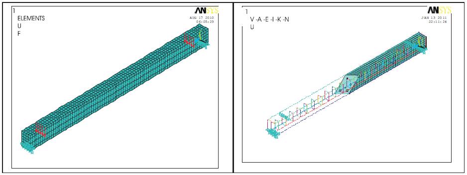
Figure 5. ANSYS Modeled Beam with and without web reinforcement for a/d =1.
The variation of deflection with load of HSC beams without shear reinforcement for a/d = 1, 2, 3, and 4 are shown in Figure 6, which indicate the increase in a/d ratio has shown reduction in shear capacity of the beam. At lower a/d ratios the ultimate load was observed to be more than twice at diagonal cracking. The deflections increased with a/d ratio, which signify that at lower a/d ratios i.e. up to 2 the strut behavior and above 2 the arch behaviour of the beams. At lower a/d ratios (up to 2), the failure was observed to be sudden compared to failure pattern observed for higher a/d ratio (a/d – 2 to 4).
The failure pattern of the beams shown in Figures 7 and 8 clearly exemplify that for a/d 1 and 2 crack initiated approximately at 45 degree called as web shear crack, across the neutral axis, a flexural crack appeared before. A compression failure finally occurred adjacent to the load which may be designated as a shear compression failure. For a/d 3 and 4 the diagonal crack started from the last flexural crack and turned gradually into a crack more and more inclined under the shear loading. The crack did not proceed immediately to failure, the diagonal crack moved up into the zone of compression became flatter and crack extended gradually at a very flat slope until finally sudden failure occurred up to the load point. The failure may be designated as diagonal tension failure. The failure patterns were found to be almost similar in both the beams with and without web reinforcement.
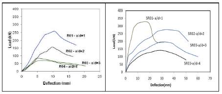
Figure 6: Load - Deflection illustration for R01-SR01 (a/d=1), R02-SR02 (a/d=2), R03-SR03 (a/d=3) & R04-SR04 (a/d=4).
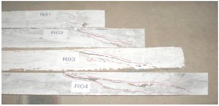
Figure 7. Crack patterns and load points of the failed specimens- R01, R02, R03 and R04
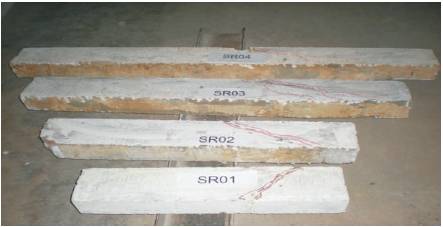
Figure 8. Crack patterns and load points of the failed specimens- SR01, SR02, SR03 and Sr04.
The experimental and ANSYS modeled Load- Deflection response of HSC beams with and without shear reinforcement are illustrated in Figure 9 .The ultimate load carrying capacity of the beams with shear reinforcement was found to be higher compared to beams without shear reinforcement which may be attributed to inclusion of shear reinforcement. The failure of the specimens without web reinforcement was found to be little sudden compared to beams with web reinforcement which is anticipated as greater energy storing capacity of beams with web reinforcement. The illustration articulate, at the initial stage of loading the ANSYS model data overlapped with the test data, where as in the post crack regime it was found to be smoother compared to experimental results. The variation in the results may be attributed to the difference in bond characteristics of concrete and reinforcement in the model and the test. The ANSYS model could predict the results modestly upto the ultimate load. The model could not predict the load-deflection response in the post crack regime of the beams as the elements are distorted above the specified limit leading to failure of the specimen. The behaviour of concrete elements modeled in ANSYS is as such that after crushing to maximum extent (that is after third crack represented in blue color in ANSYS crack and crush model) the material shows a softening behaviour in all direction resulting in distortion of all the linked elements.
The first crack observed in the shear span during the testing of the beam was found to be similar in the ANSYS predicted model. In further stages of loading of ANSYS predicted model the cracks propagated through the shear span and new cracks emerged at the constant moment zone at the loads closer to ultimate load. The orientations of cracks predicted by the model are inclined in the shear span region and vertical in constant moment region. The vertical cracks propagated deeper towards neutral axis in the beams with web reinforcement than in beams without web reinforcement. The crack patterns and the order of cracks predicted by ANSYS model are in confirming with experimental observations. During the test process, at ultimate load the inclined crack in shear span widened and concrete under the load point crushed. The ANSYS model predicted the crushing of concrete at ultimate by indicating large distortion of element nodes. The crack patterns indicate purely shear failure at a/d =1 and 2 and shear –flexure failure at a/d =3 and 4.The crack pattern observed in ANSYS model at failure is illustrated in Figure 10 and 11.The model illustrated first stage cracks in red color and second stage cracks in green and final stage cracks in blue.
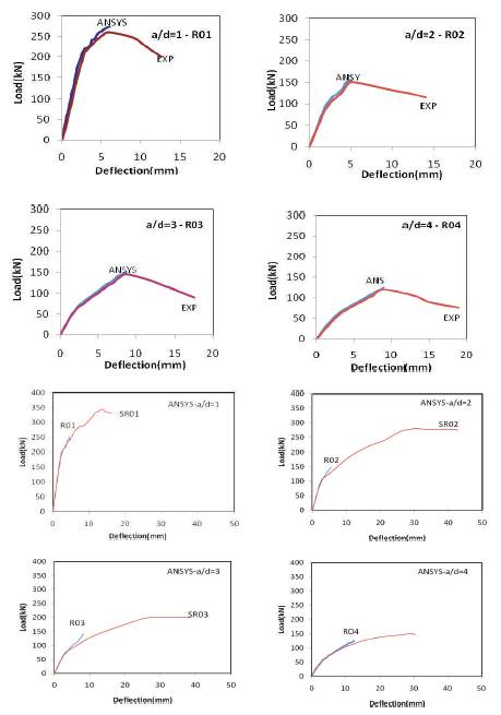
Figure 9. Comparison of response of Load – Deflection for Experimental and ANSYS results for a/d =1, 2, 3 & 4.
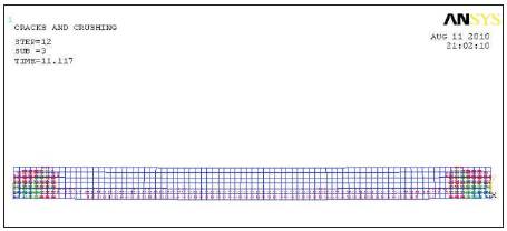
Figure 10. Crack Pattern of ANSYS modeled beam without web reinforcement at failure, a/d =1
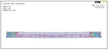
Figure 11. Crack Pattern of ANSYS modeled beam with web reinforcement at failure, a/d =2
With the discussion on the experimental and ANSYS model studies conducted on HSC beams with and without web reinforcement the following conclusions can be drawn: