Figure 1. Flowchart of Implementing PCL in Visualization Interface with Build-in Point Cloud Processing Features
Handling LiDAR (Light Detection and Ranging) data has been growing ever since the high demand in automotive vehicle and surveillance system application. This paper introduces a conversion tool which allows the extraction of point cloud data while rearranging the data to fit point cloud library (PCL) input format which is known as Point Cloud Data (PCD). Scanse Sweep LiDAR is used as an initial guidance in LiDAR data acquisition where it is able to export .csv and .xyz data. Conversion such as cartesian to polar have also been included due to Scanse Sweep hardware. csv format arranged in polar form. Moreover, converted point cloud is processed using PCL greedy fast triangulation method for 3D modelling and random sample consensus (RANSAC) algorithm used for plane segmentation in which each features are combined in a single application constructed using LabVIEW.
LiDAR started out in the early 1960s, is specifically designed for meteorological applications such as cloud measurement and mapping moon surfaces (Goyer and Watson, 1963). It is known for its high precision measurement due to its smaller beam divergence for detailed mapping application (Portland State University, 2017) and vast distance acquisition (LiDAR Tutorial, 2017). Two best geomatic techniques that are widely used in automation and mapping applications are photogrammetry (Pastra et al., 2003) and laser scanning (Kovacs et al., 2006) which complements one another in terms of visualization and 3D feature extraction. This however, still contains major limitation in regards to obtaining detailed features when the scene is located indoors which may require scanning acquisition in multiple positions to avoid blind spots. Prior in solving such limitation, a system is needed to withstand the ability of processing static and mobile LiDAR data.
With the advantage in recent times where real-time enabled 3D sensors such as Kinect or Scanse Sweep have become widely available at a decent price whereas a library known as PCL built by a community aimed to emphasize the importance of code sharing and 3D processing which enhances the research opportunity in featuring data processing and 3D mapping applications (Rusu and Cousins, 2011) PCD, also known as the 'point cloud data' format, coexist with Point Cloud Library (PCL) due to the support by several extensions that are not available in existing formats, and are set as a requirement for usage of PCL in n-D point cloud processing (Point Cloud Library, 2017).
In this paper, data are collected using Scanse sweep hardware with the goal to complement point cloud library (PCL) in performing point cloud visualization, 3D modelling using fast triangulation method and plane segmentation for further object classification. These features are then combined into an individual user interface which enables researchers to gain full flexibility in processing LiDAR data through MSVC C++ language. Furthermore, to ensure compatibility of PCL, conversion tools from xyz, csv and ascii to .pcd are required. The following work includes the discussion on how the conversion tools came about to ensure it meets the .pcd standard.
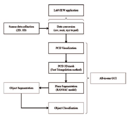
The idea of this work is to construct a Scanse Sweep compatible system that is able to perform basic PCD visualization, 3D modelling, segmentation and object classification using PCL through C++ language. Figure 1 shows the overall flowchart of implementing PCL in visualization interface with build-in point cloud processing features.
Figure 1. Flowchart of Implementing PCL in Visualization Interface with Build-in Point Cloud Processing Features
Moreover, prior to ensuring PCL being able to process the data output from Scanse Sweep hardware, a converter is built using LabVIEW 64 bit. The reason why LabVIEW is chosen for building the conversion tool is due to better flexibility in parsing and decoding binary input files to the proper PCD format. C++ is used to construct the primary feature of a LiDAR system due to PCL supported in C++ language. The Graphical User Interface (GUI) is built using Qt Creator4.3.1 and Qt Designer. CMake is used to build binary files from source code for each individual feature and also QVTKWidgets that is required for visualization UI in Qt.
The difference between PCD and other point clouds format such as PLY, STL, OBJ etc, is that PCD is designed to carry more than just xyz points but also the intensity, colours and surface normals. Whereas formats such as PLY is designed for polygon files, STL for stereolithography CAD system and OBJ is meant for geometry definition. Every file format consist of a header which stores properties declaration regarding the data store in the file. PCD is chosen due to its capability in storing in binary, and also supports char, short, int, float, double data types suited for data extraction in this interface application.
Compatibility is always the main challenge to ensure the processing system to accept the correct input data. Some of the point cloud data format recorded in azimuth are not supported by most of the software. Therefore, the converter is needed for the visualization software that process PCD format files that recorded xyz data. This converter can achieved simplicity in performing conversion without the cause of confusing the user. Figure 2 shows the steps of inserting .csv file (records azimuth data) as an example to perform conversion to .pcd (records xyz data). The formula for conversion of 3D polar coordinates (f, q, r) to 3-D Cartesian coordinates (x, y, z) is as below:
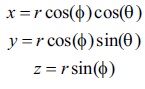
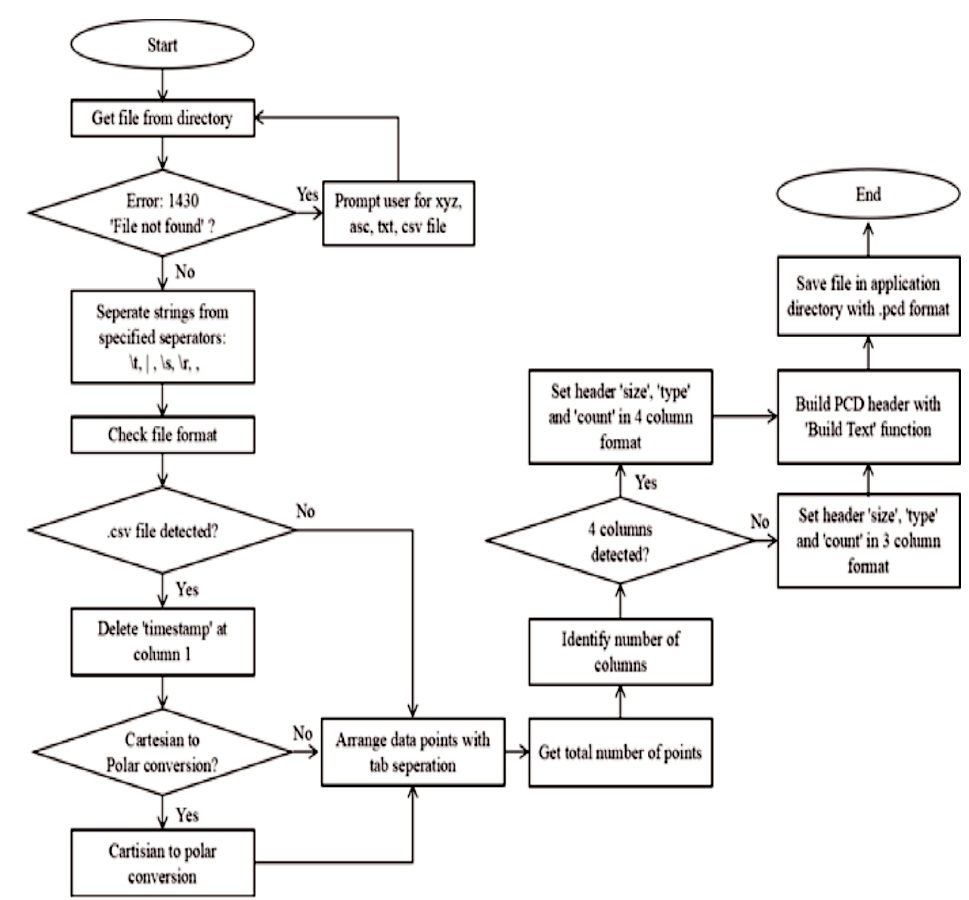
Figure 2. Conversion Tool Program Flow Constructed in LabVIEW
The fast polygon triangulation method is widely used for computer graphics which translates points to polygon structures. The method includes greedy algorithm, difference of convex hull and horizontal decompositions, however in this paper, the fundamental choice of reconstructing 3-D model will be to use greedy algorithm (Sansoni et al., 2009; Narkhede and Manocha, 1995).
The triangulation method works well with unorganized points which can be widely seen from LiDAR data due to multiple repetitive scans across the same region. The algorithm maintains the unorganized points in a list at which meshing can be grown on (Point Cloud Library, 2017). By using PCL, first the PCD is loaded into Point Cloud <PointXYZ>
The PCD converter has the simplicity of consisting of only consist three main user prompt options which are file path, conversion checkbox and event buttons as shown in Figure 3.
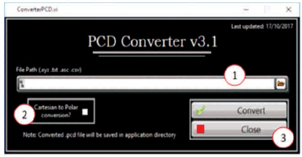
Figure 3. PCD Converter Tool GUI
In this experiment, the conversion tool is being tested by comparing 2D data acquired through scanse sweep device. The first point cloud data is acquired by converting the XYZ exported from scanse sweep to PCD data suited for PCL cloud_viewer for visualization. The second point cloud data is plotted using the sweep visualizer software. Both plots are compared as shown in Figure 4.
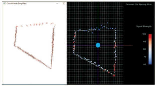
Figure 4. XYZ to PCD Plotted with Cloud_Viewer (Left) Vs Sweep Visualizer Software Plot (Right)
The comparison above gain sufficient evidence that the converted xyz to pcd file format retains the information carried which also displays the acceptance of PCL cloud_viewer towards the converted pcd file. The following experiment performs the conversion from .csv to .pcd with cartesian to polar feature enabled. Below results demonstrate the conversion taking place from the export .csv data to converted PCD by using the azimuth and distance data shown in Figure 5.
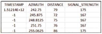
Figure 5. Scanse Sweep .csv Data Format
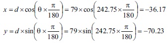
Given azimuth, θ = 242.75 and distance, d = 79, x and y can be calculated as shown below:
By comparing the data before and after conversion, as shown in Figure 6, it is noticeable that the first row in csv may not be in the first row of the converted pcd. This is due to the original xyz data arranged according to the angle of the Scanse sweep, whereby the angle of the pcd file is arranged from minimum to maximum order before performing cartesian to polar conversion. Moreover, the first column of the .csv data is removed as there is no need for timestamp in pcd format, whereas the signal strength is remained in pcd but is presented as rgb data.
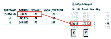
Figure 6. Cartesian to Polar Conversion (csv to pcd)
The following experiment is performed with the aim to comprehend the parameters’ configuration using PCL greedy surface triangulation method. A near flat surface point cloud is used as the input PCD for PCL greedy surface triangulation. The maximum nearest neighbors are varied from 3 to 15 where it is noticeable that the greater the nearest neighbors provided for the search, the better the surface reconstruction can be performed. The results are gathered in Figure 7. An observation has been made from Figure 7 which proved that even by increasing the nearest neighbors point, the surface triangulation of the object may not be fully covered, leaving holes on the surface. However, having neighbors search point as low as 10 also may lead to incomplete sur face reconstruction. This then leads to the suspicion on setMu() variable which determines the acceptable distance to the nearest points.
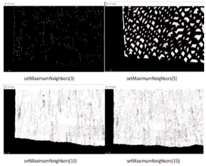
Figure 7. Triangulation of 3D Plane Surface while Varying the Maximum Nearest Neighbour
The aim of this experiment is to fine tune RANSAC algorithm plane segmentation on a specific point cloud data by adjusting the distance threshold between the randomly selected points with the plane model. The threshold value used in this experiment determines the acceptance of inlier and rejection of outlier compared to the plane model. Based on the results shown in Figure 8, by setting the distance threshold to as low as 0.001, the sensitivity of detecting a plane is high which results in multiple planes detected on a single plane. The reduction of threshold picks up small uneven distortion of the plane which will then be filtered as an individual plane. Setting the distance threshold to 1 resulted in acceptance of all points including the supposingly, outliers from the plane model. Similar case to threshold = 0.1, where the mug on the desk is identified as part of the plane.
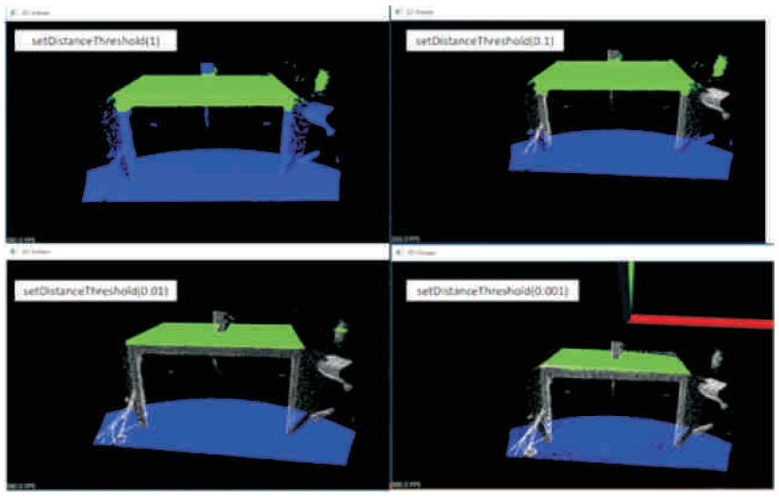
Figure 8. RANSAC Segmentation Distance Threshold of 1, 0.1, 0.01 and 0.001
Therefore, ideal value for performing RANSAC can only be determined through the distance between each point cloud that may be affected by factors such as sampling rate or rotating speed of the motor, but also the consistency of acquiring the points of an object. Uneven surface may cause detection of multiple plane detection, therefore a pre-process step such as mean least square surface reconstruction is needed prior to performing RANSAC plane segmentation.
From the whole work, it can be concluded that the necessity of point cloud extraction to the correct format may increase the flexibility in processing the data, which in this case, conversion of .csv and .xyz to .pcd that is acceptable from PCL. Furthermore, with the operating simplicity of 3D modelling using fast triangulation method and plane segmentation using RANSAC algorithm due to its minimal parameters configuration needed, the methodology are suitable for setting up new LiDAR system for further algorithm testing.