[1]
To avoid sudden and brittle failure of bending members, the Indian Standard Code prescribed limits on the minimum and maximum values of longitudinal reinforcement ratios. In the present paper, a computer program in C-language is developed for moment-curvature relationship of the reinforced concrete beams with minimum percentage of steel. The moment-curvature relationship helps in understanding the strength characteristics, flexural behaviour, and ductility characteristics of RC beams under flexure. The influence of grade of concrete, grade of steel, percentage of tension steel, and geometric parameters like depth of the beam section on the moment-curvature relation of reinforced beams is studied. Based on the Moment-curvature diagrams, it is found that the first crack moment and the ultimate moment of concrete increases with increase in the grade of concrete due to the increase in the interfacial toughness. The energy absorption capacity and curvature ductility of the concrete is found to be decreasing with the increase in the compressive of the concrete and percentage of steel due to the increase in brittleness of the concrete.
Minimum steel is necessary from shrinkage and creep considerations and guarantee accidental overloads due to vibration, settlements, etc. To avoid sudden and brittle failure of bending members, the Indian Standard Code prescribed limits on the minimum and maximum values of longitudinal reinforcement ratios. Longitudinal steel ratios for flexural members specified by the Indian code depend only on the steel strength. But it may be prudent to include the concrete strength also in the equation of such limits.
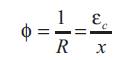
Curvature is defined as the rotation of the member per unit length. In flexural members, moment-curvature relationship is assumed to fully represent the structural response of the beam cross section. Moment-curvature relationship for reinforced concrete sections can be generated using the equilibrium equations, the compatibility equations, and the material models. From Figure 1, curvature is equal to the ratio of strain compression fibre to the depth of neutral axis.
Hence, 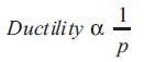
where, p= percentage of steel, = Strain gradient, R= Radius of curvature, = Maximum strain in concrete, = c s Maximum strain in steel, x = Neutral axis depth, d = Effective depth of the beam, dx = Small portion of curvature of beam, d= Small angle subtending between the small portion of curvature of beam, M = Ultimate u moment.
Eventhough M increases with the increase of p, ductility u decreases.
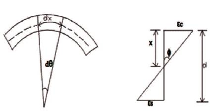
Figure 1. Relation between Curvature and Strain in Concrete
Stiffness is the ability of a member to resist deformation. Ductility is the ability of a member to deform at failure load without a significant loss in strength. Ductility depends on the member's (i) Strength and (ii) Stiffness. Strength is the ability of the member to resist the loads. Ductility is defined with respect to the strains (Strain ductility), curvatures (Curvature ductility), and deflections (Deflection ductility). Strain ductility depends on the type of material. Strain ductility is defined as the ratio of ultimate strain to yield the strain. Strain ductility can be studied using Stress-Strain diagrams. Curvature ductility depends on the size and the shape of the cross section of the member. Curvature ductility is defined as the ratio of curvature at ultimate load to the curvature at yield load. Curvature ductility is studied using Moment-Curvature diagrams. Deflection ductility depends on the entire configuration of the member and the entire loading acting on the member. Deflection ductility is defined as the ratio of ultimate deflection to yield deflection. Deflection ductility can be studied using Loaddeflection diagrams.
The ratio of curvature at failure () to the curvature at first u yield () is called as the flexural ductility or curvature y ductility. The flexural ductility of an RC section can be expressed as

Curvature ductility is influenced by tensile reinforcement ratio, compressive strength of concrete and yield strength of reinforcement.
Ductility is very important criterion in the design of structures in earthquake prone regions. Increase in the ductility of the structure reduces the induced seismic forces and hence reduces the probability of the collapse of the structure. Moment-curvature relationship predicts the strength, stiffness, and the ductility characteristics of the crosssection. Accurate prediction of the ultimate load and the moment curvature response helps in the evaluation of adequate margin of safety for concrete structures against failure.
Charif, A., Shannag, M. J., & Dghaither, S. (2014) [ 1] present the analytical and experimental results on the ductility of reinforced lightweight concrete beams and columns in the form of moment curvature relationships and compares the response with that of normal reinforced concrete members. The experimental part was limited to flexural tests on beams made of lightweight concrete. The latter was obtained with the natural lightweight aggregates. Lightweight concrete beams and columns showed a more ductile behavior than the normal concrete members and the analytical model reproduced the response with very good accuracy. Lightweight concrete ductility was more pronounced in columns subjected to axial compressive forces and bending.
Espion, B., and Halleux, P. (1988) [ 2] conducted a series of tests on rectangular RC beams subjected to bending and normal compressive forces and evaluated them. Then, a comparative study was made using two theoretical models namely, 1. CEB model proposed by Favre and Koprna, 2. Proposition model by Espion and Halleux. Second model considered tension stiffening effects on moment-curvature whereas the first model considered fully cracked stiffness in pure bending.
Jadhav, T. V., & Gundakalle, V. D., (2015) [ 3] developed a computer program to find Moment-Curvature relationship. Strength and ductility properties were studied for varying grades of concrete and depths of beams. It was found that the moment carrying capacity increases moderately with the increase in the grade of concrete. Curvature also increases with the grade of concrete. Single reinforced beam section showed higher increase in curvature compared to double reinforced section. For medium grade of concrete, the curvature was more in single reinforced beams, but for higher grades of concrete, the double reinforced sections showed more ductility. The increase in depth increases the moment carrying capacity moderately keeping the curvature unchanged.
Kwak, H. G. & Kim, S. P., (2002) [ 4] proposed a model wherein the beam elements used represent the structural response by two nodes at both ends and simplified the finite element modeling and analytical process, besides effectively describing the bond-slip behavior. Correlation studies between the analytical and the experimental results have been conducted to establish the validity of proposed algorithms. Tension softening branch and bond slip was considered to study the moment-curvature relationships of RC sections.
Murthy, D., & Reddy, S. (2010) [ 5] used the characteristic equations of stress-strain curves to study momentcurvature characteristics of beams of fly ash concrete. Theoretical procedure was validated by conducting an experimental investigation on under-reinforced fly ash concrete beams and found a good correlation between both kinds of values of moment and curvature. The fly ash replacement was done for different values and that showed very good improvement in flexural strength.
Oehlers, D. J., Ali, M. M., Griffith, M. C. (2008) [ 6] have shown that shear-friction theory can be used to simulate the rotational behaviour of concrete members due to concrete softening. Shear friction approach is used to treat softening behaviour of concrete both as a material property and a mechanism. It was also shown how the ductility of a reinforced concrete section depends on all the Mohr-Coulomb parameters and enhanced by lateral restraint that was induced by the presence of internal stirrups or external jacketing. A generic mathematical model was developed considering effective stress at the commencement of softening which depends on the concrete compressive strength as well as the confining stress due to lateral restraints. It was shown that the hinge rotational capacity depends on the interface slip which can be derived from partial-interaction theory.
Olivia, M., & Mandal, P. (2005) [ 7] developed a computer program to predict moment-curvature and available curvature ductility of reinforced concrete beams with or without axial loads. Influence of concrete strength, percentage of longitudinal reinforcement and transverse reinforcement spacing on moment-curvature relation was studied. Results indicate that the curvature ductility increases with the increase of longitudinal reinforcement and concrete strength. Transverse reinforcement spacing does not have any significant influence on the curvature ductility.
Shushkewich, K. W. (1990) [ 8] developed a unified set of equations to determine the stresses in cracked and uncracked partially pre-stressed concrete sections. Maintained the continuity of all parameters at cracking while the neutral axis moves from bottom flange to web and upwards.
Siddique, M. A. A., & Rouf, M. A. (2006) [ 9] studied the influence of concrete compressive strength, yield strength of steel and reinforcement content on the curvature ductility of single reinforced concrete beams and doubly reinforced concrete beams. It was observed that the ductility of a singly RC beam decreases as the tension steel content is increased and the presence of compression steel increases the ductility significantly. For the same reinforcement content, the increase in compressive strength of concrete increases curvature ductility of reinforced concrete section and for a double reinforced section rate of increase of curvature is more than that of a single reinforced section. The ductility of RC beams decreases as the strength of reinforcement is increased.
Srikanth, M., Kumar, G. R., & Giri, S., (2007) [ 10] presented a procedure for finding analytical Moment Curvature behaviour of statically determinate reinforced concrete beams considering the confinement offered by shear reinforcement to concrete in compression zone. Moment Curvature behaviour obtained using the selected confinement models are compared with experimental results. It was observed that the results obtained from the selected models were close to the experimental values. However, it was observed that the analytical values obtained using Mendis and Cusson model are closer to the experimental results when compared to that obtained using the other models.
In general, concrete structures are designed by satisfying two criteria, namely safety and serviceability. Safety criterion checks whether the structure is safe in carrying the designed load or not. Serviceability criterion checks whether the developed deflections and crack widths are within the permissible limits or not. The evaluation of adequate margin of safety of concrete structures against failure can be assured by the accurate prediction of ultimate load and the complete moment-curvature response. Moment-curvature diagrams help to predict the strength, stiffness, and ductility characteristics of the section.
Moment-curvature relationships of concrete members with different percentages of reinforcement are shown in Figure 2. The moment curvature relationship of un-reinforced beam exhibits a sudden fall of moment capacity beyond the ultimate moment. Since no reinforcement is present, the failure is sudden and brittle in nature; Figure 2 (a) shows the moment curvature relationship of such un-reinforced beam. If reinforcement less than the minimum reinforcement is provided, then the moment curvature response would be as shown in Figure 2 (b). It implies that this reinforcement content is not sufficient for providing additional moment of resistance beyond cracking moment. If minimum reinforcement is provided, the member continues to take the moment equal to cracking moment for increased curvature beyond cracking. The moment curvature response of such a member is shown in Figure 2 (c). Reinforcement content beyond the minimum reinforcement increases the moment carrying capacity of the member more than the cracking moment. The moment curvature response of such a member is shown in Figure 2 (d). In the present study, influence of minimum flexural reinforcement ratio, grade of steel, grade of concrete, and size of the member on reinforced normal strength concrete are studied through moment-curvature diagrams. The variation of stress and strain across the beam section is shown in Figure 3. In this regard, the strain compatibility method was used to estimate the minimum flexural reinforcement of RC beams, considering the tensile capacity of concrete also. Minimum flexural reinforcement ratio was determined using the BIS: 456-2000. A program in C-language is written to determine the moment-curvature response of the beam. Bi-linear stress-strain relationship is used as a material model for concrete in tension and second degree parabolic model (suggested by Hognestad) for concrete under compression. Bi-linear stress-strain diagram is used as material model for steel in tension. The stress-strain diagrams used for material models are shown in Figure 4 and Figure 5.
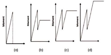
Figure 2. Moment Curvature Relationship of Concrete Members with Different Percentage of Reinforcement
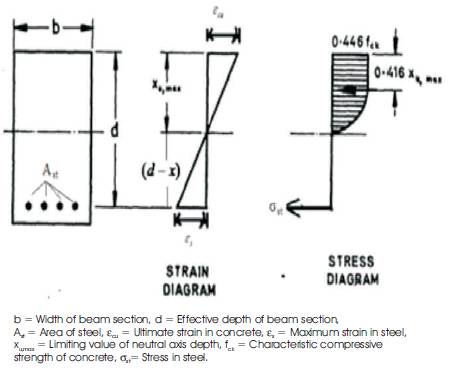
Figure 3. Variation of Stress and Strain across the Beam Section
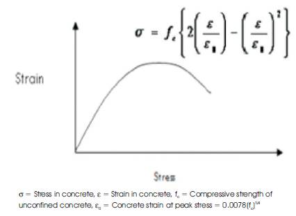
Figure 4. Material Model for Concrete In Compression
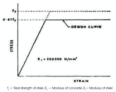
Figure 5. Material Model for Steel in Tension
Assumptions made in the development of momentcurvature relationship of reinforced concrete beams are:
Material model for concrete in compression is assumed as presented in Figure 4.
Material model for steel is assumed as presented in Figure 5.
The relationship between stress f and strain epslj is as i follows:
(i) When epslj < 0 (compression)
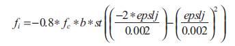
where, epslj = Strain in concrete,
f = Characteristic compressive strength of concrete
(ii) When (tension--- pre-cracking)
where, f = Tensile strength of concrete,
E = Modulus of concrete,
f = Stress in the i strip of beam.
The stress-strain relationship for the reinforcement is divided into two regions:
(a) When
(b) When
where, f = yield strength of steel.
A step-wise procedure adopted for developing moment curvature relationship of RC beam is detailed as below.
The variations considered in the present investigation are three grades of concrete (M20, M30 and M40), three grades of steel (Fe250, Fe415, and Fe500), three sizes of beams (250 mm, 350 mm, and 450 mm deep and 230 mm wide). The percentage of longitudinal reinforcement is calculated using BIS 456-2000 for RC beams.
The details of Curvature at first crack, Moment at first crack, Curvature at first yield, Moment at first yield, Ultimate Curvature, Ultimate Moment and Ductility Index are presented in Table 1. The first crack moment and the ultimate moment of concrete increases with the increase in the grade of concrete. This is due to the increase in the interfacial toughness of the concrete as presented in Figures 6-14 and Table 2, respectively.
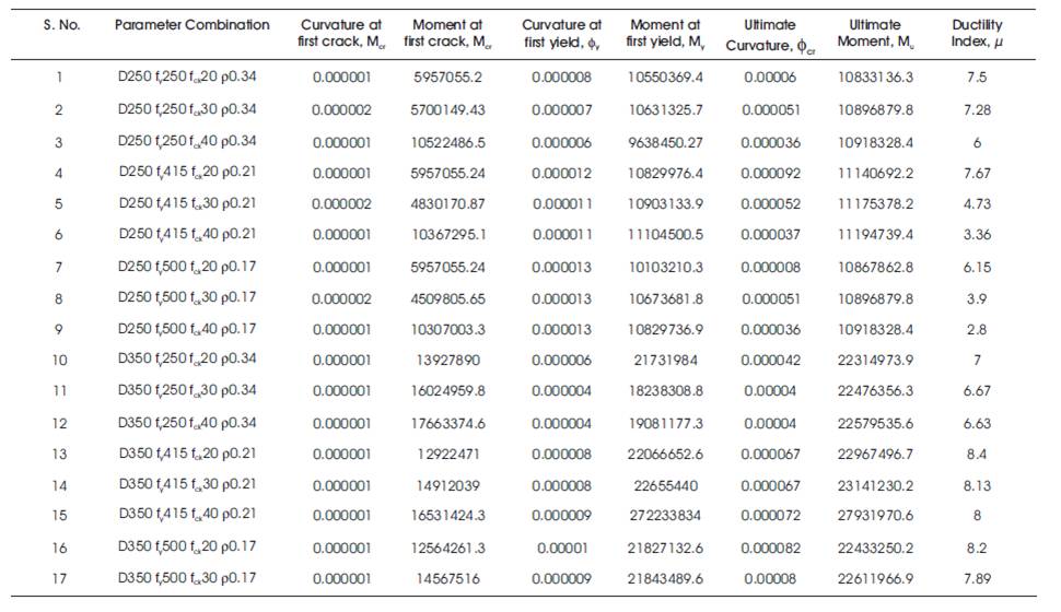
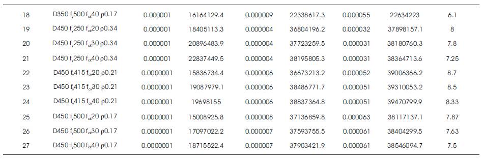
Table 1. Moment and Curvature at First Crack, Moment and Curvature at Ultimate and Ductility Index Values
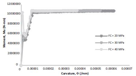
Figure 6. Moment-Curvature for b = 250 mm, D = 250 mm, f = 250 Mpa, =0.34
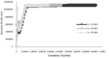
Figure 7. Moment-Curvature for b = 250 mm, D = 250 mm, f = 415 Mpa, =0.21
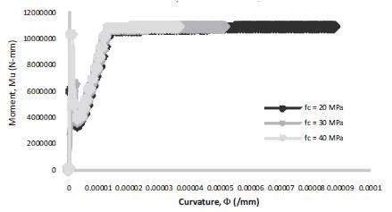
Figure 8. Moment-Curvature for b = 250 mm, D = 250 mm, f = 500 Mpa, =0.17
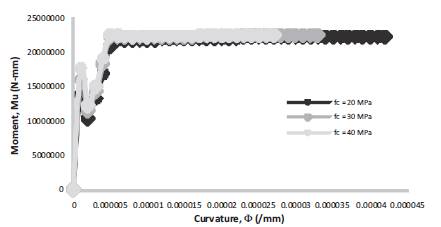
Figure 9. Moment-Curvature for b = 250 mm, D = 350 mm, f = 250 Mpa, =0.34
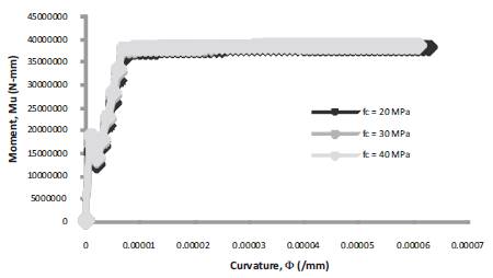
Figure 10. Moment-Curvature for b = 250 mm, D = 350 mm, f = 415 Mpa, =0.21
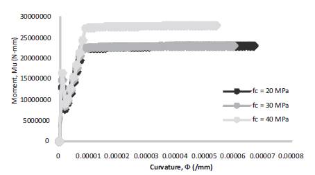
Figure 11. Moment-Curvature for b = 250 mm, D = 350 mm, f = 500 Mpa, =0.17
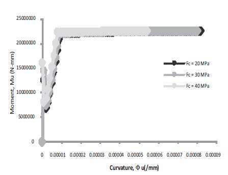
Figure 12. Moment-Curvature for b = 250 mm, D = 450 mm, f = 250 Mpa, =0.34
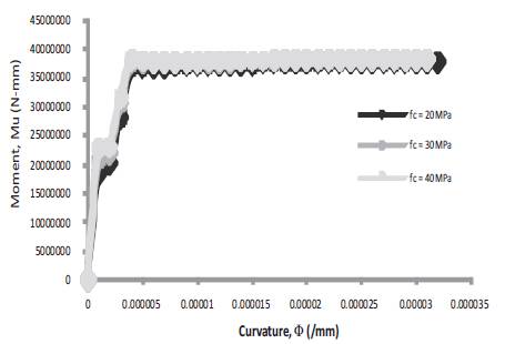
Figure 13. Moment-Curvature for b = 250 mm, D = 450 mm, f = 415 Mpa, =0.21
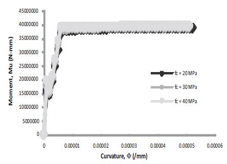
Figure 14. Moment-Curvature for b = 250 mm, D = 450 mm, f = 500 Mpa, =0.17
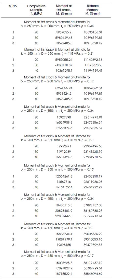
Table 2. Moment at First Crack and Moment at Ultimate for Different Grades of Concrete, Steel and for Different Sizes of Concrete Beams
The energy absorption capacity of concrete is found to be decreasing with the increase in compressive nature of the concrete. This is due to the increase in brittleness of concrete with the increase in compressive strength. Energy absorption capacity of concrete is calculated as the ratio of the curvature at ultimate to the curvature at first yield point. Variation of ductility index is presented in Figures15- 23 and Table 3 respectively.
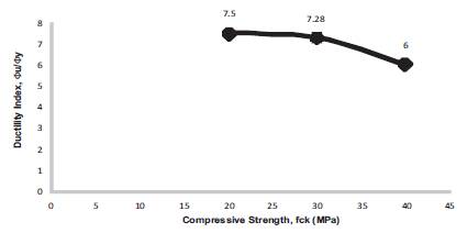
Figure 15. Ductility Index for b = 250 mm, D = 250 mm, f = 250 Mpa, f = 20, 30, 40 Mpa, = 0.34
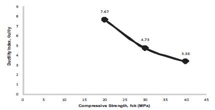
Figure 16. Ductility Index for b = 250 mm, D = 250 mm, f = 415 Mpa, f = 20, 30, 40 Mpa, = 0.21
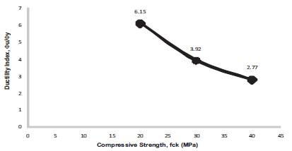
Figure 17. Ductility Index for b = 250 mm, D = 250 mm, f = 500 Mpa, f = 20, 30, 40 Mpa, = 0.17
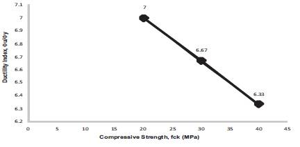
Figure 18. Ductility Index for b = 250 mm, D = 350 mm, f = 250 Mpa, f = 20, 30, 40 Mpa, = 0.34
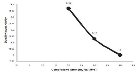
Figure 19. Ductility Index for b = 250 mm, D = 350 mm, f = 415 Mpa, f = 20, 30, 40 Mpa, = 0.21
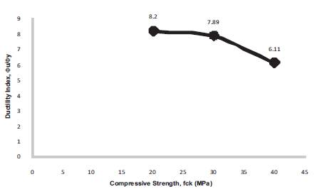
Figure 20 Ductility Index for b = 250 mm, D = 350 mm, f = 500 Mpa, f = 20, 30, 40 Mpa, = 0.17
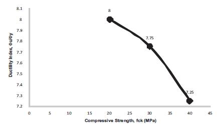
Figure 21. Ductility Index for b = 250 mm, D = 450 mm, f = 250 Mpa, f = 20, 30, 40 Mpa, = 0.34
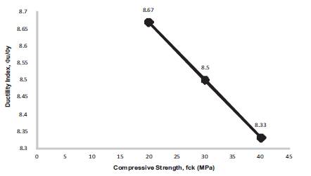
Figure 22. Ductility Index for b = 250 mm, D = 450 mm, f = 415 Mpa, f = 20, 30, 40 Mpa, = 0.21
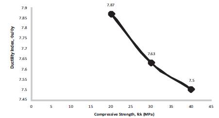
Figure 23. Ductility Index for b = 250 mm, D = 450 mm, f = 500 Mpa, f = 20, 30, 40 Mpa, = 0.17
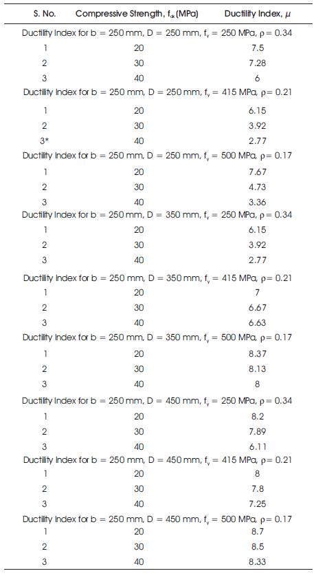
Table 3. Ductility Index For Different Grades of Concrete Beams with Different Percentages of Tension Reinforcement
In the present paper, Moment-Curvature response of reinforced concrete beams is studied for different grades of concrete, different grades of steel, different sizes of beams and different tension steel percentages. It is found that the moment capacity of the concrete increases with the increase in grade of concrete. This is due to the increase in the interfacial toughness of concrete. The energy absorption capacity of the concrete is found to be decreasing with the increase in compressive strength of the concrete. This is due to the increase in the brittleness of concrete with the increase in compressive strength.