Figure 1. Damaged Instrument Tube, due to Adequate Support System [9]
This paper explains the various causes of an instrument tubing failure, risk involved and the mitigation path to avoid such incidents in plants. These impulse tubings are employed/installed to measure pressure, flow and levels in a system and/or equipment. Corrosion on tubing fittings, incorrect installation (either due to poor workmanship or non compliance of installation/process hookup), use of incorrect tools, faulty or ignored nuts & ferrule compression fittings, inadequate design tubing support systems, mishandling & improper storage of tube and its fitting are some of the root causes. These lead to a number of problems, including safety issues, plant breakdown, costly regulatory agency fines, higher maintenance cost, energy loss and environmental hazards. The risk involved in an instrument tubing failure relates to process safety hazards, such as loss of containment due to crack in the affected tubing that leads to fugitive emissions, fires, explosions and other employee safety issues. The most serious problems occur when instrument tubing and its fitting component fails causing leakage of process fluid such as gasoline, oil, gas or other volatile, corrosive fluid (sulphur compounds) or toxic gases (such as H2S). These can cause fires, explosions or other serious safety hazards such as toxic chemical, gas leakage or acid spraying onto field craft. Generally, tubing failure cases are noticeable in areas such as booster stations, turbine driven pumps, compressors systems, tubing connection for pressure, flow transmitters & pressure gauge, areas where vibrations are present such as pipe racks (with air coolers), and platforms of vibration sources (turbine or diesel generator). The paper details out the possible reasons, hazards and suggested mitigation path to achieve improved availability.
Oil & gas, petrochemicals, chemicals, and power generation industries extensively employs the uses of instrument tubing in process instrumentation, chemical inhibition, impulse lines, and utility application over a range of temperatures, pressures and flow. Instrument tubing and tube fitting failures have been observed across upstream, midstream and downstream. Process fluid & hydrocarbon release incidents occur in process plants during the life cycle, i.e. pre-commissioning, commissioning, startup, warranty period and normal operation, due to instrument tubing and tube fitting failures. These incidents cause production losses, downtime, breakdown of facility/unit, contamination of products and serious environmental safety. The effects of instrument tubing and tube fitting failures can be viewed in terms of life cycle cost (capex and opex), management costs, serious environmental safety hazards and increased risk to field the operator in a plant. These incidents signify the need for a suboptimal installation /process hookup, detailed engineering design of tubing support system, skilled workmanship and improved control measure of instrument tubing and tube fitting failures to avoid the liability of high downtime costs and serious safety hazards risk on plant, due to failure of instrument tubing and compression tube fittings. The major contributing factors to various failure of tubing, tubing connection and its fittings are categorized as,
This paper provides the complete study about the risk involved in instrument tubing and tube fitting failures, cause of instrument tubing failures, typical area of tubing failures and the mitigation plans for protecting them. One can have an overview about this phenomenon and can also think upon the solutions to avoid that.
The expanding use of the instrument tubing in potential industrial enviroment requires detailed engineering design for clamp support of improved control measures to avoid accountability of high breakdown costs and safety hazardous, due to failure of instrument tubing and its fitting components. Incorrect, improper process hookup installation, wrong selection of tube material, use of incorrect tools, faulty or ignored nuts and ferrule compression fittings, inadequate design of piping and tubing clamp support systems, improper storage and mishandling of tube and its fitting, poor system design can lead to a number of problems, including safety related problems, plant breakdown, costly regulatory agency fines, maintenance cost, energy loss and environmental responsibility. The proposed different mitigation plans is considered useful and cost effective for the protection and prevention of instrument tubing and its fitting conmponents from unusual failures. In this paper, the authors have mentioned the reason which may or may not apply to all the instruments, but this paper will serve as a food for thought to challenge traditional installations and mitigation paths. The mitigation paths suggested may attract cost and feasibility for those should be assessed with respect to life cycle cost.
There can be a numbers of factors, which influence the instrument tubing and tube fitting failures in process industries as discussed as follows,
Use of improper or nonstandard pre-assemble tools may affect the compression tube fittings and instrument tubing that, results in leakage of tube fittings. Insufficient torque applied for the tightening of components of compression tube fittings [1] (such as ferrules, nuts and tube) fails to properly compress the ferrule around the tube. It can lead to subsequent process fluid leakage. Manual bending of tube while during instrument tubing fitting in construction plant creates abrades across the bending area.
Compression tube fitting style is the most common type of tubing fittings for process instrumentation as well as in chemical inhibition, impulse line, hydraulic lines and utility application, which uses a compressible ferrule [3] to perform the task of sealing fluid pressure. Sometimes instrument tubing failure may be caused by the excessive tightening of components of compression tube fittings. Excessive tightening of the compression fitting nuts, causing over-compressed ferrule results in damage of the tube body. It can lead to subsequent process fluid leakage.
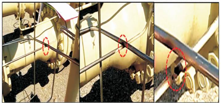
Vibration/pulsation is the major contributing factor to various tubing related failures. Excessive vibration causes the impulse line connected between process measuring instruments and the pipe line header to crack and allow leakage of process fluids as shown in Figure 1. For example - If an instrument tube connected between a stationar y remote mounted process measuring instruments (such as pressure) on a pump discharge line. This arrangement can lead to instrument tubing and tube fittings failures, due to inadequate design of tubing support system and inability to absorb the vibration stresses [10]. Sources of vibration/pulsation in process plants are booster stations, turbine driven pumps, compressor systems [11], area where vibration are present (such as pipe racks with air coolers and platforms of vibration sources), irrespective of whether the pump is operating or not and that all pumps are coupled through the discharged pipeline.
Figure 1. Damaged Instrument Tube, due to Adequate Support System [9]
Instrument tubing and compression tube fitting failures are also noticeable, during pneumatic testing of impulse line and tube fittings in operating plant. The use of nonstandard leak test agent (such as washing powder or caustic soda) invokes corrosive reaction of tubing material, during pneumatic testing of tube and compression tube fittings in operating plant. The use of nonstandard leakage test agent, which gets settled near the location where fitting bites the tubing and compression ferrules. Thus nonstandard gets agent (such as Sodium Hydroxide (NaoH) and Sodium carbonate (NaCo )) accelerating the corrosion chemical reaction in 3 the presence of moisture or water vapors with tube body and compression tube fitting materials.
Improper storage and mishandling of the instrument tubing and compression tube fittings during installation is another important factor, which influences the instrument tubing and compression tube fittings performance. Dragging of instrument tubing from receiving dock to the point of installation in fabrication yards or across any surface (such as trucks beds, shelves, storage racks, the floor and the ground of any plant) produce abrades and create burr on the outside of the tubing.
These burred, abraded and out of round instrument tubing cannot be fitted with the internal diameter of ferrule or the body bore properly and causes leakage of process fluids. This is especially important for gas services. The Low density gases such as helium, Argon and Hydrogen cannot be sealed with damaged tubing. Improper storage of instrument tubing in open warehouse or area including moistures, high or variable relative humidity, elevated temperatures or corrosive vapors invoke the risk of corrosion on tube metals and also accelerates the formation of metallic film.
Commonly ignored factor for failures of the instrument tubing and compression tube fittings are the inadequate design of tubing clamp supports system to address vibration challenge. The improper design of tubing clamp supports the remote mounted pressure gauges /transmitters installed at discharge of vibration sources, results in failure of the instrument tubing and compression tube fittings, due to transmission of vibration/pulsation from tap header to the tubing fittings at pressure gauges/transmitters. It can lead to leakage of process fluids in environment. Generally, across industries installation hookups are based on service, however these should also address nearby vibration.
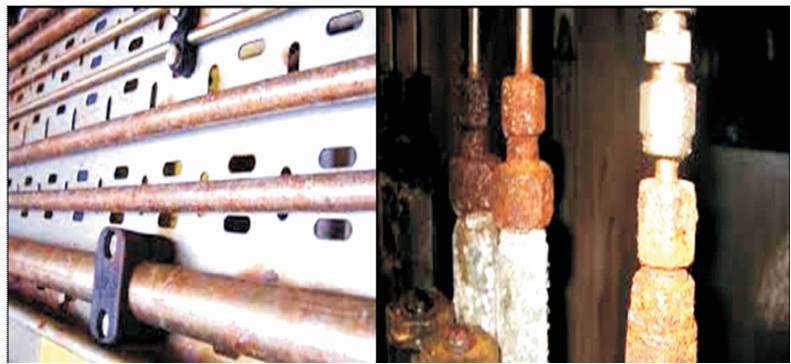
Corrosion is a serious problem that leads to the deterioration of the instrument tubing wall and compression tube fittings which results in corrosion induced tubing failures in a matter of months. Many of the industrial process or during different process reaction of the plant, reactive gases are released which contains Sulfide and Chloride and other corrosive compounds. These industrial corrosion reactive gases combined with a high or variable relative humidity and in the presence of salt mist or saliferous environment (near offshore or marine application) can generate harsh environment. This harsh corrosive environment accelerates the corrosive chemical reaction of tubing wall and also invokes the formation of metal film. Formation of galvanic and crevice corrosion [1] frequently occur between instrument tubing and tube support system (as shown in Figure 2) due to accumulation of water/ sea water between instrument tube and tubing clamp on wall. Crevices and spaces exist between tubing and tube supports, in tubing clamps, between adjacent tubing runs, and underneath contamination and deposits that may accumulate on tubing surfaces as shown in Figure 3.
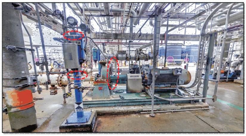
Figure 3. Corroded Instrument Tube
Galvanic corrosion is also an important reason for failures of instrument tubing and compression tubing fittings [2] . Generally, all metals have a property of specific relative potential. When two dissimilar metals of different properties come in contact in the presence of high or variable humidity and elevated temperature, which implies that, substantial amount of moisture condensate on the tube and at the fitting materials. The presence of moisture in between dissimilar metals accelerate the flows of low electric energy from metal having the higher potential to the metal having lower potential. The results of this galvanic action are the corrosion of the metal with higher potential. Mostly, galvanic corrosion occurs between tubing material and tubing support system (as shown in Figure 3) due to accumulation of water, salt-mist, sea water or condensation of moisture. Corrosion and slow process clubbed with other factors like support system design, tightening of ferrule compression fittings increases the risk of instruments tubing and compression fittings failures.
Incorrect improper process hookup installation, wrong selection of tube material, faulty or ignored nuts & ferrule compression fittings, poor system design can lead to a number of problems, including safety related problems, plant breakdown, costly regulatory agency fines, maintenance cost, energy loss and environmental hazards.
Risk involved in an instrument tubing failure relates to process safety and environmental hazards, such as loss of containment due to crack in the affected tubing that leads to fugitive emissions, fires, explosions and other safety and environmental issues. The most serious problems occur when instrument tubing and its fitting component fails causing the leakage of process fluid such as gasoline, oil, gas or other volatile, corrosive fluid (Sulfide or chloride Compounds) or toxic gases (such as H2S). These can cause fires, explosions or other serious safety hazards such as fatality due to toxic chemical, gas leakage [7].
Risk involved in an instrument tubing failure relates to breakdown or sometimes even causing shutdown of the process, which can result from the breakdown of process safety mentioned or simply from having to shutdown a pipeline and production facilities in order to replace incorrectly installed broken fatigue tube and damaged equipment.
There can be a number of causes of subsequent facility breakdown, including fire suppression activities [8], released process containment manifesting, line shutdown, personnel evacuation and eventually having to rebuild or repair the lines, replacement equipment, etc.
When an impulse line or instrument tubing failure causes an instrument to fail, even if there is no release of process fluid or serious safety issues. But still, breakdown can occur as a result of the process needing to shutdown in order to replace significant damage instrument & equipment. Instrument tubing failure rarely affects other instrument or equipment of the process to fail, although instrument tubing failure is usually an indication that there is a problem. In most of the cases, skilled plant worker will simply replace the effected tubing with new one and move on. When another tubing failure occurs, the plant worker will do the same, until the main cause of the failure, such as a misaligned pump, causing the plant to shutdown the line, resulting in more costly, unplanned breakdown and major maintenance time.
Generally, tubing failure cases are noticeable in areas [6] such as,
In this section, the authors suggest the mitigation paths for instrument tubing in process instrument, chemical inhibition, impulse line, hydraulic lines, and utility application over a wide range of temperature, pressure and flow. There are some important mitigation plans that considered as the most useful and cost effective to prevent, minimize or control the risk of tubing related failures and also to avoid the risk of corrosion and chemical attack.
Most of the instrument tubing assemblies in process plant failed at nut and ferrule compression fittings, due to the application of non-standard pre-assemble tools for tightening of compression fitting assemblies [5] such as,
All these problems can be overcome by the proper use of standard tools as per the manufacture standard. These are,
The use of nonstandard leak test agent (such as washing powder or caustic soda) invokes corrosive reaction of tubing material, during pneumatic testing of tube and compression tube fittings. This corrosive reaction of instrument tubing and compression fittings clubbed with vibration causes failure of instrument tubing. These nonstandard leak test agent is stagnated in the gap between tube, nuts and compression ferrules. These nonstandard agent (such as Sodium Hydroxide NaoH and Sodium Carbonate NaCo3) accelerates the corrosion chemical reaction in the presence of moisture or water vapors with tube body and compression tube fitting materials and start the formation of metal film. The application of proper leak test agent (such as snoop liquid leak detector) as per the manufacture standard avoids acceleration of unusual formation of corrosion layer. The leak test agent contains noncorrosive and nonflammable formula, and also corrosion inhibitor for added protection.
Proper handling and safe transportation of the instrument tubing and compression tube fittings during installation of tube lines avoids abrades, burrs on the outside of the tubing from receiving dock to the point of installation in fabrication yards or across any surface (such as trucks beds, shelves, storage racks, the floor and the ground of any plant). These burred, abraded and out of round instrument tubing cannot be fitted with the internal diameter of ferrule or the body bore properly and causes leakage of process fluids. Appropriate storage of instrument tubing is to be maintained in controlled atmosphere to avoid the risk of corrosion on tube metals and also accelerates the formation of metallic film.
The jacketing around the instruments tubing [1] offers reliable prevention or protection from the risk of corrosion and chemical attack of corrosive fluids and also meets the plant requirement. It also provides a protection against mechanical drags, abrades, impacts, stresses, abrasions, and insulates the instrument tubing fluids from ambient environment. Jacketed tubing provides protection from sea water application causing pitting corrosion of the exposed tubing materials or crevice corrosion in the gap between the tubing and supports. The extrusion of thermoplastic or polyurethane coatings on the tubing is an economical attractive solution for instrument tubing to prevent chemical reaction. Jacketed tubing is a cost effective solution for instrument tubing of less resistant alloy, which are highly exposed and directly affected from the salt-mist, sea water, and moisture, saliferous and corrosive environment.
It is widely used in industries. The demerit being that the pump discharge line vibrates at a different frequency and the station is fixed. Thus Point A as shown in Figure 4 becomes vulnerable for a failure as ferrule is biting the tubing. The possible solutions can be options 2 & 3 as follows.
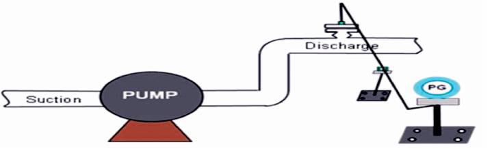
Figure 4. Option-1:Clamp Support System
It is well known and widely used as shown in Figure 5.
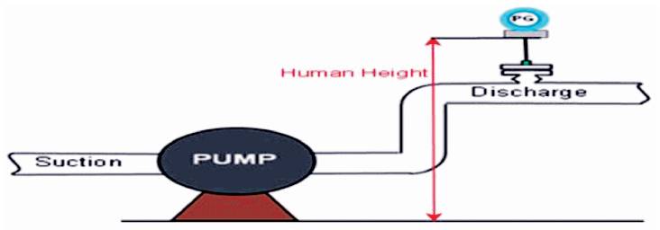
Figure 5. Option-2 direct mounting on Pipeline
In this arrangement as shown in Figure 6, the support is taken from the discharge line so that the entire downstream system inclusive of tapping point and instrument vibrate at the rate of same frequency.
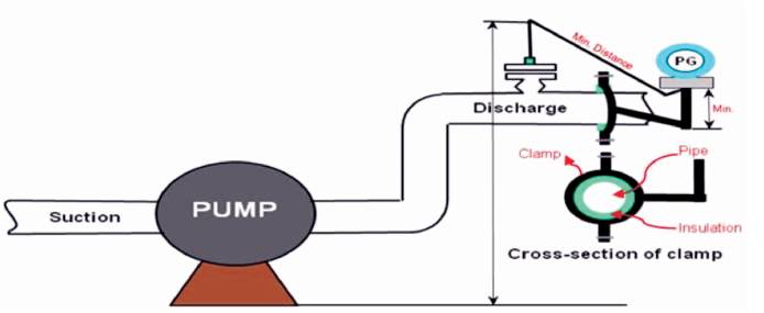
Figure 6. Option-3 Clamp support system
The expanding use of the instrument tubing in potential industrial environment requires detailed engineering design for clamp support of improved control measures to avoid accountability of high breakdown costs and safety hazardous, due to failure of instruments tubing and its fitting components. The proposed different alleviation path finds it useful and cost effective for the protection of instrument tubing and its fitting components from unusaul failures. In this paper, the authors mentioned the reason which may or may not apply to all the instruments, But this paper will serve as a food for thought to challenge traditional installations. The mitigation paths suggested may attract cost and feasibilty that should be assesed with respect to life cycle cost.