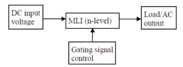
Figure 1. Block Diagram of Multilevel Inverter
The multilevel inverter utilization has been increased since the last decade. These new type of inverters are suitable in various high voltage and high power applications due to their ability to synthesize waveforms with better harmonic spectrum and faithful output. This paper analyzes the Total Harmonic Distortion (THD) performance of a three phase 5- level inverter. The five level inverter is configured with RL load for the analysis. Three different Pulse Width Modulation (PWM) schemes are proposed for the analysis of five level inverter. The simulation results are presented to prove that THD is reduced with different Pulse Width Modulation scheme.
An inverter is commonly used in variable speed AC motor drives to produce a variable three-phase AC output voltage from a constant DC voltage source, which has two voltage level (+VDC, -VDC). The output waveform of inverters should be sinusoidal for efficient operation. But the output of conventional two level PWM inverters would be a square wave (or) quasi square wave [1]. The square wave is rich in harmonic content. To minimize the output voltage distortion with improved fundamental voltage, the multilevel inverter concept has been implemented. Advantages of this multilevel approach include good power quality, good electromagnetic compatibility (EMC), low switching losses, and high voltage capability. The main disadvantages of this technique are that a larger number of switching semiconductors are required for lower-voltage systems and the small voltage steps must be supplied on the DC side either by a capacitor bank or isolated voltage sources.
These multilevel inverters are suitable for high voltage and high power application due to their ability to synthesize waveforms with better harmonic spectrum. Numerous topologies have been introduced and widely studied for utility and drive applications. Multilevel Pulse Width Modulated (PWM) inverters are gaining importance due to the fact that the lower order harmonics in the output waveform can be eliminated without any increase in the higher order harmonics, unlike the regular two level PWM inverters [2], [3]. Multilevel inverters provide more than two voltage levels. As the number of levels reaches infinity, the output Total Harmonic Distortion (THD) approaches to zero. This inverter generates almost sinusoidal staircase voltage with only one time switching per line cycle [1], [4]. The output voltage waveforms in multilevel inverters can be generated at low switching frequencies with high efficiency and low distortion [5]. In recent years, beside multilevel inverters, various Pulse Width Modulation (PWM) techniques have been also developed. Space Vector PWM (SVPWM) technique is one of the most popular techniques gained interest recently [6], [8]. This technique results in higher magnitude of fundamental output voltage available as compared to sinusoidal PWM.
However, SVPWM algorithm used in five-level inverters is more complex because of large number of inverter switching states. Multilevel inverters are that the voltage stress on each switching device is reduced. In addition, multilevel waveforms feature have less harmonic content compared to two level waveforms operating at the same switching frequency [9].
The objective of this paper is to present an implementation scheme for different PWM scheme for five level inverters. The PWM switching times for the inverter legs are directly derived from the sampled amplitudes of the reference phase voltages. For experimental verification of SPWM, THIPWM and SVPWM schemes, the authors have used a five-level inverter configuration with RLC load [10].
The general block diagram of multilevel inverter is shown in Figure 1. Figure 2 shows a five level cascaded H-bridge multilevel inverter. The converter consists of two series connected H-bridge cells, which are fed by independent voltage sources. The outputs of the H-bridge cells are connected in series such that the synthesized voltage waveform is the sum of all the individual cell outputs [11]. The output voltage is given by V=V1 +V2 , where the output voltage of the first cell is labeled V1 and the output voltage of the second cell is denoted by V2. There are five levels of output voltage, i.e., 2V, 1V, 0, -1V, and -2V. The main advantages of cascaded H-bridge inverter is that, it requires least number of components, modularized circuit, and soft switching can be employed. But the main disadvantage is that when the voltage level increases, the number of switches increases and also the sources, this in effect increases the cost and weight. The cascaded H-bridge multilevel inverters have been applied where high power and power quality are essential, for example, static synchronous compensators, active filter and reactive power compensation applications, photo voltaic power conversion, uninterruptible power supplies, and magnetic resonance imaging. Furthermore, one of the growing applications for multilevel motor drive is electric and hybrid power trains [2]. Figure 3 shows the simulation model of three phase 5 level inverter which is used in this paper.
Figure 1. Block Diagram of Multilevel Inverter
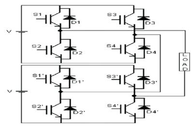
Figure 2. Five Level Cascaded H-bridge Multilevel Inverter
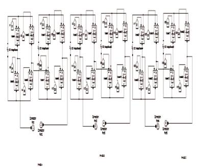
Figure 3. Simulation Model of a Three Phase 5-level Inverter
The advantages of cascaded H-bridge multilevel inverter MLI configuration are as follows,
Pulse-Width Modulation (PWM) is a technique where the duty ratio of a pulsating waveform is controlled by another input waveform [6]. The intersections between the reference voltage waveform and the carrier waveform give the opening and closing times of the switches [12].
The Sinusoidal Pulse-Width Modulation (SPWM) technique produces a sinusoidal waveform by filtering an output pulse waveform with varying width. A high switching frequency leads to a better filtered sinusoidal output waveform. The desired output voltage is achieved by varying the frequency and amplitude of a reference or modulating voltage [7].
The variations in the amplitude and frequency of the reference voltage change the pulse-width patterns of the output voltage, but keep the sinusoidal modulation [13].
As shown in Figure 4, a low-frequency sinusoidal modulating waveform is compared with a highfrequency triangular waveform, which is called the carrier waveform. The switching state is changed when the sine waveform intersects the triangular waveform. The crossing positions determine the variable switching times between states.
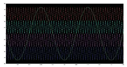
Figure 4. Reference and Carrier Frequency Signal of the Proposed SPWM
If certain portion of the third harmonics wave is injected into the sine wave, the resulted demodulated wave will appear as saddle- like shape as shown in Figure 5 and the amplitude will obviously decrease. With keeping m<1, the amplitude of the fundamental wave can exceed that of the triangle wave and thus utilization ratio of the DC-bus voltage increases. Figure 6 shows the waveform of the proposed Third Harmonic Injection Pulse Width Modulation.
Space Vector PWM was also adapted for multilevel inverters. In a multilevel inverter, Space Vector PWM algorithm is developed based on the equations for a twolevel Space Vector PWM inverter. All of the small triangles that form the hexagon of active vectors are classified based on their orientation. Based on their orientation, each triangle is treated as a certain sector in a two-level inverter, and the calculation of dwell times for the voltage vectors may be found [11]. The algorithm has been verified in a five-level inverter in this paper.
The SVPWM switching pattern generation is not realized with offset voltage computation from a modulus function. A simple way of adding a time offset Figure 4. Reference and Carrier Frequency Signal of the to the inverter-gating signal, to generate the SVPWM pattern, from only the sampled amplitudes of reference phase voltages is explained. The proposed SVPWM signal generation does not involve checks for region identification, as in the SVPWM scheme. Also, the algorithm does not require either sector identification or look-up tables for switching vector determination as required in the conventional multilevel SVPWM schemes. Thus the scheme is computationally efficient when compared to conventional multilevel SVPWM schemes, making it superior for real-time implementation. The proposed SVPWM algorithm can easily be extended to any multilevel inverter configurations. Figure 7 shows the waveform of Space Vector Pulse Width Modulation.
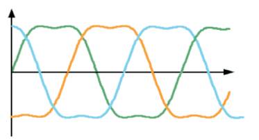
Figure 5. 3 Phase THIPWM Modulated Wave
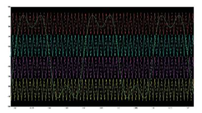
Figure 6. Reference and Carrier Frequency Signal of the Proposed THIPWM
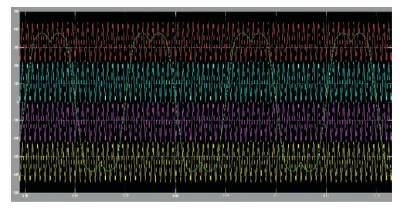
Figure 7. Reference and Carrier Frequency Signal of the Proposed SVPWM
In an individual H-bridge, the output voltage is positive voltage (+Vdc), zero voltage (0Vdc), and negative voltage (Vdc). Hence the desired output voltage levels for a 5-level inverter are ±2V, ±1V, and 0V [8]. The switching states for the voltage levels are presented in Table 1.
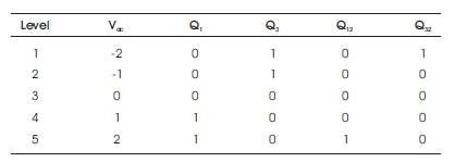
Table 1. Switching States of Proposed 5-level Inverter
The Matlab Simulink simulation results of the proposed inverter containing resistive load along with control logic would be obtained by the simulation model as depicted in Figure 8. Figure 9 shows the output waveforms of a 5- level Inverter using SPWM switching technique in Simulink. In Figure 10 and Figure 11, the FFT analysis of voltage and current for SPWM switching technique are shown respectively. The output waveform for 5-level inverter using THIPWM switching technique is shown in Figure 12 and the analysis for total harmonic distortion for the THIPWM switching technique for the proposed 5-level inverter is shown in Figure 13 for voltage and Figure 14 for current. Figure 15 illustrates the 5-level inverter output waveforms of voltage and line current for the SVPWM switching technique in Simulink. Figure 16 shows the FFT analysis of THD for voltage in 5-level inverter using SVPWM switching technique and Figure 17 shows the FFT analysis of THD for current in 5-level inverter using SVPWM switching technique. The overall analysis for output voltage and current for different switching techniques for the proposed 5-level inverter is shown in Table 2.
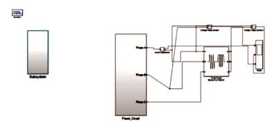
Figure 8. Simulation Model of a Three Phase 5-level Inverter along with Switching Control Logic

Figure 9. Output Waveforms of 5-level Inverter using SPWM Switching Technique in SIMULINK
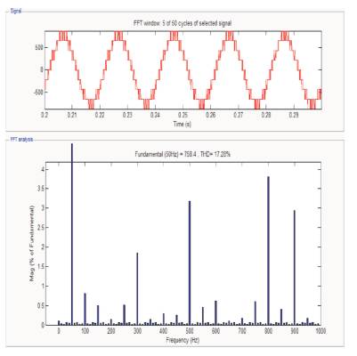
Figure 10. FFT Analysis of THD for Voltage in 5-level Inverter using SPWM Switching Technique
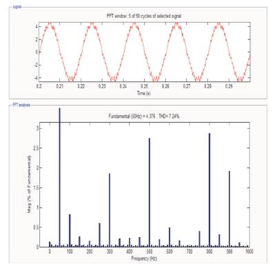
Figure 11. FFT Analysis of THD for Current in 5-level Inverter using SPWM Switching Technique
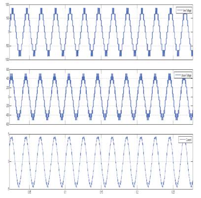
Figure 12. Output Waveform of 5-level Inverter using THIPWM Switching Technique in SIMULINK
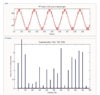
Figure 13. FFT Analysis of THD for Voltage in 5-level Inverter using THIPWM Switching Technique
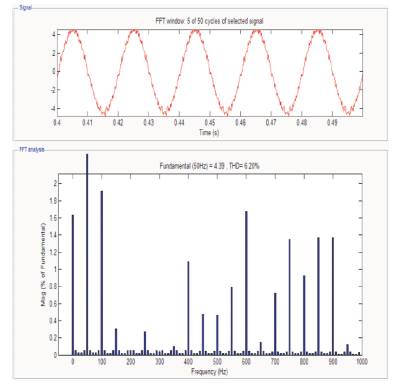
Figure 14. FFT Analysis of THD for Current in 5-level Inverter using THIPWM Switching Technique
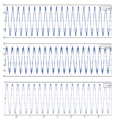
Figure 15. Output Waveform of 5-level Inverter using SVPWM Switching Technique in SIMULINK
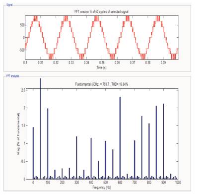
Figure 16. FFT Analysis of THD for Voltage in 5-level Inverter using SVPWM Switching Technique
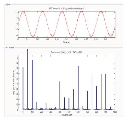
Figure 17. FFT Analysis of THD for Current in 5-level Inverter using SVPWM Switching Technique
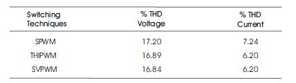
Table 2. THD of Output Voltage and Current for different Switching Techniques at Fundamental Frequency (50 Hz)
In this paper, the proposed three phase five level inverter is used with three different PWM techniques for switching. Simulation using Matlab/Simulink software was performed to show the performance of different switching techniques on three phase five level inverter. THD performance of voltage and current is shown for different techniques as in Table 2.