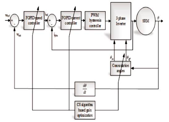
Figure 1. Structure of SRM with Proposed Closed Loop Control Topology
The intelligent controller represents a combined performance of both the Fractional Order PID controller (FOPID) and Cuckoo Search Algorithm (CSA). In this paper, an intelligent controller for the speed control of Switched Reluctance Motor (SRM) drive system using multi-objective function is proposed. The innovation of the proposed method users in enhanced probing skills, ensures the cutback of the irrational arbitrary production and exhibits supreme skills in successfully addressing and adapting the intricate optimization issues. The FOPID is offered carte-blanche in tuning the constraints in view of the fact that the order of derivative and integral do not constitute the integers. It may pave the way for further vibrant accomplishment when compared to the conventional PID controller. Now, the CSA optimized the gain parameters of the controllers for the speed error and current error regulation loops of the SRM drive control mechanism. Further, the proposed control algorithm goes a long way in optimizing the commutation angles for bringing down the lofty torque ripples. Based on the proposed algorithm control parameters, the speed control of the SRM drive has been enhanced. The proposed intelligent control technique will be implemented in the MATLAB/Simulink platform.
The Electrical Drives (EDs) are very significant part of industry automation for successful productivity. The requirement of EDs depends upon the available mains and load characteristics for that particular application [1]. In industrial use, the EDs are usually required to run at very high speeds. For such applications, the Switched Reluctance Motor Drives (SRMDs) have drawn more interest of research. It is due to the reasons of economical alternative to Permanent Magnet Brushless Motor Drives (PMBLMDs), mechanically and electrically more rugged than the conventional AC and DC motors like Induction Motors (IMs) and Synchronous Motors (SMs) [2-5]. Other than industrial automations, SRMDs are also accommodated in household applications, hybrid and electric vehicles, wind power plant, aeronautical and aircraft applications, etc. [6].
SRMDs have the merits of simple structure, inexpensive manufacturing and reliability capability, high degree of independence between phases, short end-turn, and low inertia with capability to operate in harsh environment like coal mining even with a wide speed range[7-10]. Generally, the SRMD is a doubly salient-pole machine, which runs on the principle of variable reluctance [11]. Here, the torque is produced by the tendency of the rotor to reach a position, where the inductance and the flux produced by the energized winding are maximized[12- 13]. But, in SRMD, its phase inductance is a non-linear function of winding current and rotor position, and also time-varying[14]. For this, the control structure requires rotor position information for an optimal phase excitation sequence.
Even though the SRMDs can produce high torque at low speeds, they suffer from inherent high torque ripples, which cause vibrations and acoustic noise[15-18]. In order to reduce these torque ripples, various control strategies are derived to the inverter of the SRMDs along with rotor position tracking. The control logic provides activation signals for the power semiconductor switches in the inverter that are synchronized with the rotor position[19]. In this scenario, a control strategy must achieve two actions simultaneously. They are adjusting the motor speed using voltage Pulse Width Modulation (PWM) and regulating the advanced firing angles as a function of the desired motor speed[20]. Nevertheless, SRMDs have highly non-linear and dynamical behaviour which makes them difficult to control[21].
In this paper, an intelligent controller for the speed control of Switched Reluctance Motor (SRM) drive system using multi-objective function is proposed. The intelligent controller represents a combined performance of both the Fractional Order PID controller (FOPID) and Cuckoo Search Algorithm (CSA). The FOPID is offered carteblanche in tuning the constraints in view of the fact that the order of derivative and integral do not constitute the integers. It may pave the way for further vibrant accomplishment when compared to the conventional PID controller. Now, the CSA optimized the gain parameters of the controllers for the speed error and current error regulation loops of the SRM drive control mechanism. Further, the proposed control algorithm goes a long way in optimizing the commutation angles for bringing down the lofty torque ripples. Based on the proposed algorithm control parameters, the speed control of the SRM drive has been enhanced. Rest of the paper is sorted as follows. Section 1 describes the literature works briefly. The objective of the work is described in section 2. The proposed work that elaborates the evidence is usually described throughout section 3. The suggested technique is briefly explained in section 4, and the suggested techniques approach with results as well as the related discussions are received throughout section 5. Finally the paper is concluded.
There has been a lot of research progressed for designing new control strategies for speed regulation of SRMDs. Some of them are reviewed here. Dehkordi Behzad Mirzaeian, et al. [22] have developed a Brain Emotional Learning based Intelligent Controller (BELBIC) to control the Switched Reluctance Motor (SRM) speed. Here, control was designed without position sensor of the rotor. The rotor position was estimated by Adaptive Neuro Fuzzy Inference System (ANFIS) from the inputs of phase flux linkages. Motor parameter changes, operating point changes, measurement noise and open circuit fault in one phase and asymmetric phases in SRM were simulated to show the robustness and superior performance of BELBIC. It was compared with Fuzzy Logic Controller (FLC) for validating its superiority.
Mademlis Christos, and Iordanis Kioskerides[23] have adopted advanced proportional-integral (PI) and Proportional-Differential (PD) controllers for speed and position controls respectively for SRM drives. A gainscheduling technique was adopted in the speed controller design. In order to improve the set-point tracking, a low-pass filter was included in the position controller. The proposed four-quadrant control scheme was based on the average torque control method. The turn-on and turn-off angles were online determined through simple formulas so as to reduce the torque ripple at an acceptable level over a wide speed range.
Wang Shun-Chung, et al. [24] have proposed two modified PI-like fuzzy logic controllers with output Scaling Factor (SF) self-tuning mechanism based on the redevelopment of control rule base for application in SRM drive system. For both types of controllers, the output SF of the controller could be tuned continuously by a gain updating factor, whose value was derived from the fuzzy logic reasoning, with the plant error and the error change ratio as the input variables. The rule bases were created based on the knowledge of the SRM's dynamic behaviour and practical experience.
Tseng Chwan-Lu, et al. [25] have presented a novel Adaptive Takagi-Sugeno-Kang (TSK)-Fuzzy Controller (ATSKFC) to regulate the speed of a SRM. The proposed controller comprised two parts, a TSK-fuzzy controller and a compensated controller. The TSK-fuzzy controller was the main controller used to approximate an ideal control law. The compensated controller was designed to compensate the approximation error between the TSKfuzzy controller and the ideal control law. The parameter variations and the external load of the SRM drive were considered to ensure the robustness of the proposed scheme. An online tuning methodology based on Lyapunov was utilized to adjust the parameters of the ATSKFC, so that the stability of the control system could be guaranteed.
Wang, S Y, et al. [26] have presented a novel Adaptive Fuzzy Cerebellar Model Articulation Controller (AFCMAC) to regulate the speed of a SRM. The proposed controller comprised two parts, a Fuzzy Cerebellar Model Articulation Controller (CMAC) and a Compensating Controller. The fuzzy CMAC learnt and approximated system dynamics. The compensating controller compensated the approximation error of the fuzzy CMAC. The parameters of the AFCMAC were adjusted online according to adaptive rules, which were derived from Lyapunov stability theory, so that both the stability of the control system and error convergence can be guaranteed.
B. Ganji, et al. [27] have presented a parametric electromagnetic model for the Switched Reluctance Generator (SRG) with the Finite Element Method (FEM) using the ANSYS Finite Element (FE) package, which can be considered appropriately for accurate analysis and optimal design of the SRG. The performance principles of the SRG were briefly explained and some important electromagnetic characteristics of the SRG including phase current and instantaneous input power were predicted using the developed electromagnetic model. Carrying out the transient analysis, there was this possibility to predict the flux waveforms within the machine and therefore a core loss model is then introduced for the SRG.
J.E. Muralidhar, et al. [28] have discussed that Brushless DC motors were promptly increased popularity because of its more efficiency & attain control characteristics with high accuracy speed. Need some digital controllers for sensing and regulating the disturbances by utilizing several control logic units. The obstacles of formal PI controller for the speed control could be regulated by Fuzzy control units with affordable stability factor. They highlight the design of the four switch converter fed BLDC drive with Fuzzy controller supports the dynamically renew the parameters of formal PI controller. The intended control units have very moderate structures because fuzzy rule in the rule based system was relevant to ease design using computer simulations. Simulation results are conferred satisfactorily in transient and steady states, low error values and with a high stability factor.
This work, deliberated about the speed regulation procedure of Switched Reluctance Motor (SRM) with Cuckoo Search Algorithm (CSA) based Fractional Order Proportional Integral Derivative (FOPID) controller. Now, the CSA methodology improves the tuning gain parameters of the FOPID controller and implemented into the two control loops of the scheme like speed loop and current loop. The FOPID is accessible carte-blanche in tuning the constraints in view of the fact that the order of derivative and integral do not constitute the integers. This work gives a brief introduction and motivation of the research. It also momentarily defines about the proposed methodology and its utilization to accomplish the optimal parameters on the basis of the load variations. Promote, the wished-for control algorithm goes a long way in improving the commutation angles for bringing down the lofty torque ripples. On the basis of the proposed algorithm control parameters, the speed regulation function of the SRM drive has been heightened. The procedure of the proposed methodology has been split into preprocessing of the actual input and reference input parameters multi-objective based optimization and the chapter ends by recitation of the thesis of closed loop topology.
The proposed closed loop control topology for the speed control of the SRM drive is depicted in Figure 1. The control model mainly has three major control actions like the current loop, speed loop, and the commutation. The speed loop is equipped with the speed controller (FOPID) to evaluate the reference currents (iref ) for the three phases of the SRM drive in accordance with the speed error (Δeω ). The reference current is used for the evaluation of the current error from the input phase current (iph ) of the SRM. Based on the current error (Δeω ), the current controller (FOPID) processes and determines the control signals. These control signals are modulated as the switching pulses using the PWM block for the voltage source inverter. The components present in the closed loop topology have been explained in the following section.
Figure 1. Structure of SRM with Proposed Closed Loop Control Topology
SRM is equipped with the salient poles on the stator and the rotor together with coils positioned around the stator poles and linked in diametrically opposite couples to constitute the phases of the motor. The excitation is switched consecutively from phase to phase as the rotor moves. The electromagnetic torque in SRM is generated by utilizing the rotor position-reliant reluctance of the magnetic path related to each phase. When a phase is animated, a reluctance torque is generated which proceeds to line up the stator and rotor poles[25]. The output voltage of the SRM is described in the following equations.
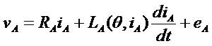
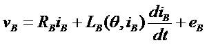
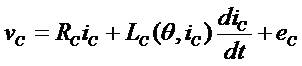
Where, vABC and iABC are the input three phase voltages and currents of the SRM drive, respectively. RABC and LABC are the respective resistances and inductances of the three phases. θ is the rotor position and eABC is the Back EMFs of the SRM drive. The inductance of each phase depends non-linearly on its current as well as the rotor position. Equations (1-3) illustrate the fact that the distributed voltage is utilized by the resistive voltage drop, the inductive voltage drop and the induced EMF. The electromagnetic torque of the SRM drive is expressed by equation (4) is given below.
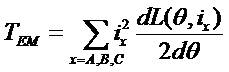
where, TEM represents the total electromagnetic torque that is present in the SRM drive due to the three phase currents. The captioned equation may be employed to obtain the mechanical system in the SRM drive which is described as follows[22].
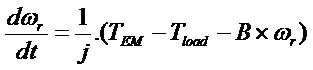
where, ωr is the angular velocity, J and B are the moment of inertia and friction co-efficient, respectively and Tload refers to the load that is applied on the SRM drive. With the variation in the load torque, the alteration in the total load to the SRM drive can be easily executed. With an eye on meeting the relative enhanced or a reduced load, the total electromagnetic torque input has to be furnished appropriately. This may be carried out by adapting the phase currents in such a way as to realize the required torque to meet the load. The proposed speed and current controller for the SRM drive is given in the following subsections.
The speed controller's input represents the speed fault, which is given by the divergence between the speed reference and the filtered speed feedback signals and its output constitutes the current command[29]. The transfer function FOPID speed controller is usually expressed in parallel form as per equation (6) shown below[30],
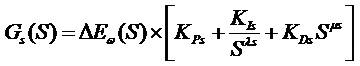
where, Gs(S) is the output of the FOPID speed controller, ΔEω(S) is the error speed, KPs is the proportional gain of the speed controller, Kls is the integral gain of the speed controller, KDs is the derivative gain of the speed controller, λ and µ are the orders of integral and derivative of the speed controller, respectively.
Each phase current control loop is endowed with a matching controller configuration comprising the FOPID current controller and a PWM controller[29] The transfer function of the FOPID current controller is habitually represented in parallel form as per equation (7) shown below[30].

where, Gs(S) is the output of the FOPID current controller, ΔEi(S) is the error current, KPi is the proportional gain of the current controller, Kls is the integral gain of the current controller, KDs is the derivative gain of the current controller, λ and µ are the orders of integral and the derivative of the current controller, respectively.
The turn on and turn off angles approach eventually decides the efficiency in execution of the SRM. Torquespeed scope, machine efficiency, torque ripple, as well as the acoustic noise are dependent, to a certain extent, on the choice of turn on and turn off angles. The mathematical equation for calculating the advancing angle is described in the following equation (8) [31].
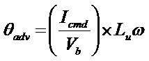
where, Icmd is the desired phase current, ω is the speed in rad/sec, Lu is the unaligned inductance, and Vb is the DC bus voltage. The mentioned control actions require the optimum control parameters, which is determined from the multi-objective function. It has been described in the following section.
The multi-objective function should minimize the error speed, current, and torque by optimally selecting the control parameters and the commutation angles. The required multi-objective function is described in the following equation (9).
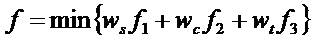
where,
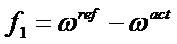
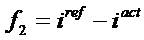
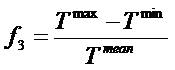
With f1 , f2 , and f3 are speed error, current error and torque ripple, ws , wc , wt are the weight coefficients in the objective functions of speed error, current error and torque ripple, respectively. The innovative coefficient technique is followed to prioritize the preferred objective function. For example, in the event of the torque ripple minimization being considered as the main objective, wt must have more value than the other two coefficients. The reported multi-objective function is subjected to the following constraints [30].

The above stated equations (14-19) are used for optimizing the control parameters. The optimization process has been done by using the CSA algorithm, which is described in the following section.
This section describes the optimization of the gain parameters by using CS algorithm. The CSA technique represents the most modern sophisticated optimization algorithm, which is appropriate for successfully addressing the incessant non-linear optimization problems[33]. The CSA was triggered by the obligate brood parasitism of certain cuckoo species by laying their eggs in the nests of host birds. Certain cuckoos have evolved in such a fashion that the female parasitic cuckoos are capable of replicating the colours and models of the eggs of certain short-listed host species. With the result, the likelihood of the eggs being neglected is reduced, thereby leading to the increase in their reproductivity[34]. In the proposed method, the CSA algorithm finds the optimal gain parameters and the commutation angles based on the multi-objective function, which is possible by taking the gain limits of the FOPID controller as the input. From the obtained optimal solutions, the deviation of the speed and current has been reduced. The algorithmic procedure to find the optimal gain selection is described as follows.
Step 1: Initialize the input host nest and cuckoo parameters like the FOPID controller gain bounds of the speed and current loop X .
Step 2: Generate the random population of n host nests using equation (20).
Step 3: Set the iteration count k=1.
Step 4: Evaluate the fitness of the nests with the assistance of the fitness equation (9).
Step 5: Estimate the maximum and minimum fitness of the initial population. The minimum values are accumulated as the best solutions.
Step 6: Create the fresh solution by means of the levy flight search mathematical formulation, which is expressed as follows.
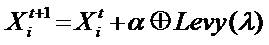
Where, α>0 is the step size, which must be linked to the extent of the issue of concern and the product  means element-wise multiplication.
In this document, we employ the Levy flight mechanism in which the step-lengths are disseminated in accordance with the probability distribution shown below.
Locate the worst nests in accordance with the probability (Pa ) and replace the worst nests by a fresh set of solutions.
Step 7: The rationalized outcomes from the levy fight search and best solutions are located by means of the multi-objective function (9).
Step 8: Check the termination standards and if they are satisfied, proceed to step 9, else return to step 3.
Step 9: Terminate the process.
Once the process is completed, the network is ready to give the better gain parameters for the different types of load conditions. The optimized gain parameters are applied to the FOPID controller.
The optimized gain parameters attained from the CSA algorithm are allowed for the FOPID controller, which performs the speed regulations in the SRM drive. This action enhances the speed control of the system for both the normal and abnormal environments. By using the attained gain parameters, the given equations (6) and (7) are rewritten as follows.
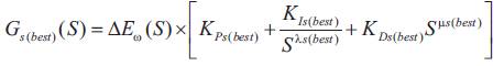
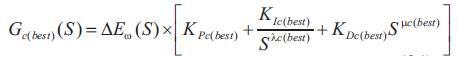
The above equations utilize the best gain parameters optimized from the CSA algorithm. The proposed method structure is described in Figure 2. Then the proposed method is implemented in the MATLAB/Simulink platform and the attained results are discussed in the following section.
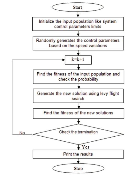
Figure 2. Structure of the Proposed Method
Implementation of the proposed methodology is carried out in the MATLAB/Simulink 7.10.0 (R2012a) platform, 4GB RAM and Intel(R) core(TM) i5. In this document, the SRM speed control is executed by the proposed optimized FOPID controller. The optimization procedure is accomplished by means of the CSA in accordance with the multi-objective function.
The 60 kW SRM investigation version is deployed for evaluating the proposed method and the constitution of the motor version is effectively elucidated in Table 1. The implemented version of the SRM together with the control method is elegantly exhibited in Figure 3. The parameters relating to the CSA, which are needed for the optimization of the controller constraints, are vividly detailed in Table 2, and the optimized gain parameters achieved by employing several methods are illustrated in Table 3.
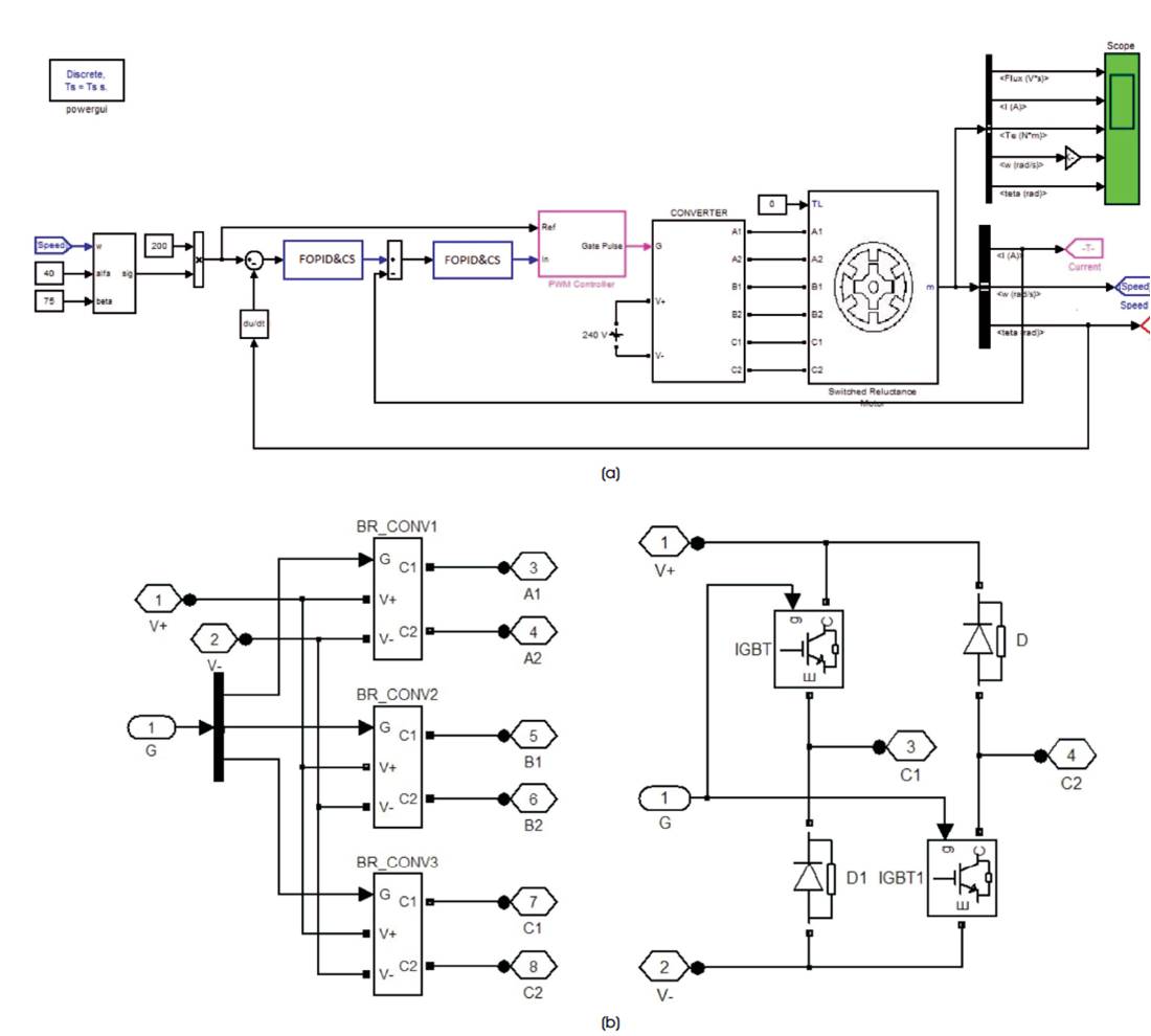
Figure 3 (a) SRM Model with Controller, (b) Converter Structure
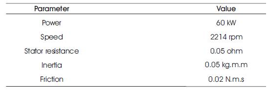
Table 1. SRM Configuration
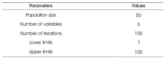
Table 2. Implementation Parameters of the Proposed Technique
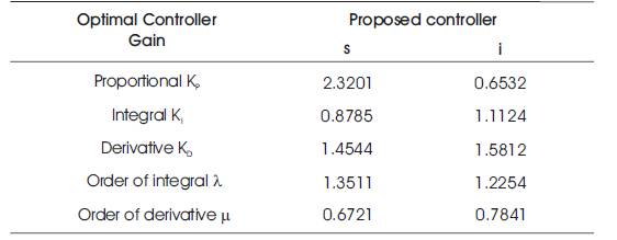
Table 3. Optimal Controller Gains Achieved using Proposed Technique
The replications of the proposed methodology are carried for a period of roughly 0.32 seconds. Nevertheless, exceedingly précised feedbacks entail the time scale modification for inductance, phase currents, and total torque within the range of 0.3 – 0.32 seconds. Performing an optimal choice of the FOPID controller parameters by means of CSA is competent to scale down the torque ripples to the minimum possible value and therefore, the diminution in the torque dip of the SRM can be achieved. From equation (4), it is crystal clear that the braking torque tends to emerge with a non-zero current in any of the phases. As illustrated in Figure 4, the positive torque area commences at the rotor position of 0.20552 rad and comes to an end at 0.2085 rad. The inductance sketch of the three phases and the rotor positions of the SRM Drives are effectively exhibited in Figure 5. The inductance is recurring at every 90o angle and the segregation between the phases is also 90o . This paper suggests a method with which the SRM controlling performance can be enhanced. Here, the FOPID control gain parameters are optimized with a multi-objective function to obtain an optimized FOPID controller. The distinction between FOPID and PID controller, lies in the fact that, in FOPID, the order of derivative and integral does not constitute an integer. This phenomenon furnishes a carte-blanche in regard to tuning the controller, which may result in superb and energetic accomplishment vis-a-vis the conventional PID [30]. The speed, the current, and the torque of the SRM represent the constraints considered in the multiobjective function. The optimal gain parameters have been instrumental in achieving an incredible reduction in the current disturbances between the two phases as illustrated in Figure 6.
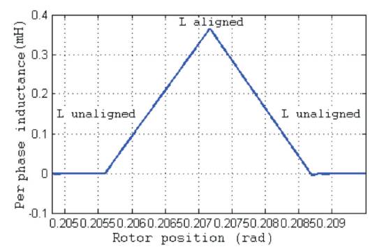
Figure 4. Per Phase Inductance Profile SRM
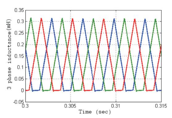
Figure 5. Inductance Profile for 3 Phase SRM
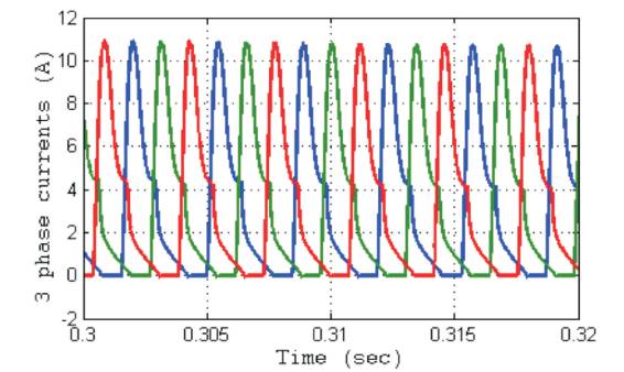
Figure 6. 3 Phase Current of the SRM using the Proposed Controller
The proposed controller skillfully addresses the hassles originating from the non-adaptive gain parameters by means of the CSA-based optimization procedure. The torque of SRM using the proposed method is shown in Figure 7. The torque ripple is considerably reduced by means of the optimization process, in relation to the graphical outcomes pictured in [29]. Further, the torque dip available between two phases is dipped deeply when compared to the modern controllers. The striking SRM speed outcomes emerging from the proposed controller appear in the appealing attire of Figure 8. It is crystal clear from the graph that the settling time ushered in by means of the proposed method is trivial vis-a-vis the peer techniques. It is proved without any iota of doubt that the proposed method shows the resilience to user in the least value in relation to that of the conventional technique. Moreover, the analysis and contrast of the proposed technique with the modern approaches emerge as telling examples of the superb speed controlling skills of the SRM, which is fine-tuned with the proposed technique.
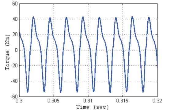
Figure 7. Torque of SRM using the Proposed Controller
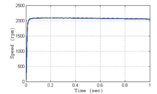
Figure 8. SRM Speed using the Proposed Controller
This paper discusses the speed control of the SRM drive system using an intelligent controller with multi-objective function. The FOPID controller combined with the CSA is denoted as the intelligent controller. The optimization based FOPID controller is efficiently and successfully implemented for solving the speed variation of the SRM drive by considering speed and current controller constraints. The meta-heuristic approach of the proposed technique is habitually employed to produce the fruitful solutions, which are highly satisfactory for scheduling the control parameters together with the large scale constraints to resolve the mega optimization hassles. The validation of the results has proved the dominating performance of the proposed methodology over the other techniques that are reported in the literature.
The FOPID control gain parameters are optimized with a multi-objective function to obtain an optimized FOPID controller. The proposed controller skilfully addresses the hassles originating from the non-adaptive gain parameters by means of the CSA-based optimization procedure. The analysis and contrast of the proposed technique with the modern approaches emerge as telling examples of the superb speed controlling skills of the SRM, which is fine-tuned with the proposed technique.