Figure1. Master Leaf Spring
The riding comfort of an automobile is greatly affected by the suspension system. Springs are crucial suspension elements, necessary to minimize the vertical vibrations, impacts and pumps due to road irregularities, vertical vibrations and impacts are buffered by variations is the spring deflection so that the potential energy is stored in spring as strain energy and then released slowly. Composite leaf spring made of Eglass/Epoxy is the best alternate to steel spring for having excellent higher strength-to-weight ratio, high energy spring capacity, excellent corrosion resistance and higher natural frequency.In the present paper, shape optimization of mono composite leaf spring was carried out with design constraints as stress and displacements. Through finite element technique, structural parameters are computed for both steel and optimized composite leaf springs. Experimental validations were done on steel and composite leaf spring for both static and dynamic conditions. The dynamic analysis is computed through Fast Fourier Transform (FFT) and MATLAB code is developed to determine the natural frequencies of the leaf springs. Composite leaf spring is found to have low deflections, less stress, weight, high natural frequency and high damping property compared to steel leaf springs. This results in fuel savings and better riding comfort in automobiles.
The increase in competition and innovations in automobile sector tends to modify the existing products or replacing old products by new and advanced material products. Also to meet the needs of the natural resource conservation and energy and economy, the automobile manufacturers have been attempting to reduce the weight of the vehicle in recent years [1]. The suspension system of a vehicle is also an area where these innovations are carried out regularly. More efforts have been taken in order to increase the comfort of the user. Appropriate balance of comfort riding qualities and economy in the manufacturing of leaf springs has become an obvious necessity. Several papers are devoted to the application of composite materials for automobiles. Design and structural analysis of variable thickness and width for cross sectional area of GFRP. End joint analysis and testing of monocomposite leaf spring is reported [1]. Design optimization of a leaf spring and application of composite structures for light weight and heavy trucks in automobile industry is discussed [2-5]. Application of composite leaf springs for suspension system by optimization of a double tapered beam section is discussed [6, 7]. Preliminary design approach developed for composite beam is reported [8]. Improvement in fatigue life is predicted for composite leaf springs as compared to steel leaf springs of parabolic geometrical sections under cyclic strain loading is presented [9,10].
Design is based on same stiffness for both steel and composite mono leaf springs. Considering same load, length of span and number of leaves and the minimum thickness is designed to be 12mm. The design selected parameters for the composite leaf spring is 40 layers, fiber thickness is 0.225mm, resin thickness is 0.075mm, Layer thickness is 0.3mm, layer width is 100mm, total thickness of leaf with 40 layers is 12mm and the leaf width is 100mm.
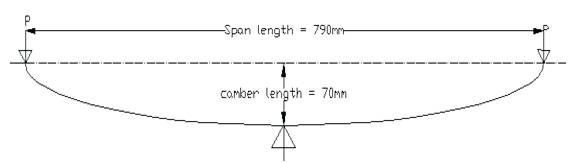
The variable thickness of mono composite leaf spring is based on uniform strength criteria. Computational analysis is performed initially with 12 mm centre thickness and the deflection and maximum stresses are calculated using COSMOS. Results show that the maximum stress is exceeding the allowable stress value of composite materials. Iterations are carried out for an increment of 1mm centre thickness and the analysis is performed. For a centre thickness of 18 mm the stresses developed are found to be within the permissible limits. The line diagram and the three dimensional solid model of the leaf spring is shown in Figure 1 and 2 respectively. The specifications of the leaf spring, material properties and ply design are shown in Table 1, 2 and 3 respectively.
Figure1. Master Leaf Spring
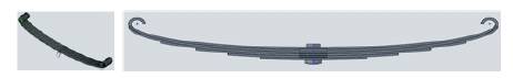
Fig.2. 3D Solid model of Leaf Spring
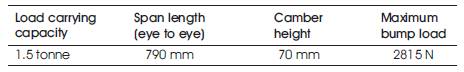
Table 1. Specifications of Leaf Spring
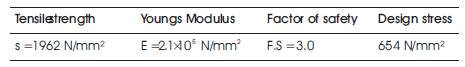
Table 2. Material Properties: Steel: 55Si2Mn90
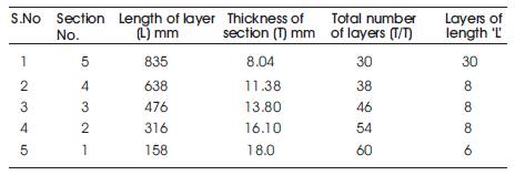
Table 3. Ply Design
Analysis is performed using the SOLD WORKS COSMOS. Deflections for different loads are observed for steel and composite leaf springs of uniform and variable thickness. The spring is treated as a simply supported beam. One end of the spring is constrained as Ux = 0, Uy = 0, Rotz ≠ 0 and Uz= 0. The other end is constrained as Uy = 0, Uz = 0 and Rotz = 0. The deformations and stresses under various loading conditions are computed by discretising the spring with 3D solid Tetrahedral element and a load applied at the centre of leaf spring. The structure is tested to a maximum load of 2815N. The computational results obtained, deflection and Vonmises stresses are shown from Figure 3 to Figure 8.
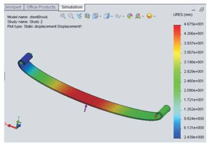
Figure 3. Deflection of Mono Steel Leaf Spring
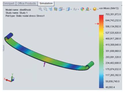
Figure 4. Von Mises stress of Mono Steel Leaf Spring
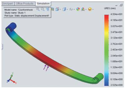
Figure 5. Deflection of Composite leaf spring (Uniform thickness)
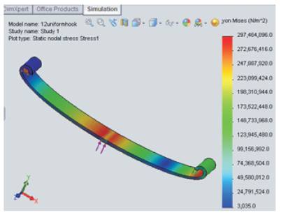
Figure 6. Von Mises stress of Composite leaf spring (Uniform thickness)
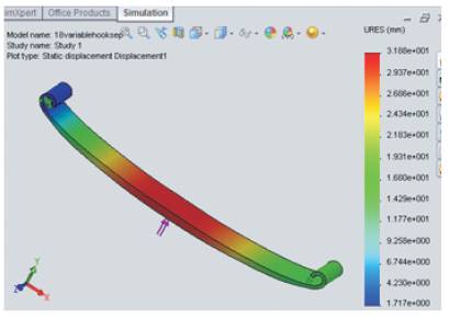
Figure 7. Deflection of Composite leaf spring (Variable thickness)
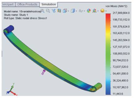
Figure 8. Von Mises stress of Composite leaf spring (Variable thickness)
The mandrel is designed using concentric circle method to obtain the leaf spring curvature and the required camber height. The mandrel setup consist of bottom, top mould and two wooden spacers to maintain thickness of the leaf spring. The required layers are laid between the moulds. Two wooden planks are fixed on either side of the moulds to prevent the distortion of FRP layers. Vents are provided on the planks to remove entrapped air. All the bi-directional fiber layers which are cut as per the design dimensions are arranged one over the other till 40 layers for the uniform thickness composite leaf spring and 60 layers as per the layup sequence designed for variable thickness composite leaf spring. In the fabrication process of composite leaf spring epoxy resin is used. For 1kg of epoxy resin 100 gm of hardener is mixed. This mixture is first applied on the wax polish and then a layer is placed on the mandrel and the resin is applied again. Sharp edges produced during the fabrication process are removed by trimming using a grinding machine. The leaf springs are tested following standard procedures recommended by SAE. The spring to be tested is examined for any defects like cracks, surface abnormalities, etc. The spring is loaded from zero to the prescribed maximum deflection and back to zero. The load is applied at the centre of the spring, and the applied pressure, developed vertical deformations i.e., deflection of the spring is observed and tabulated. The manufactured leaf springs and the composite leaf being tested is shown in Figure.9.
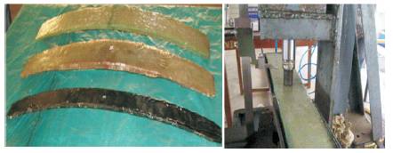
Figure 9. Steel Leaf Spring, Mono Composite Leaf Spring with uniform and variable thickness and Testing
Hameg setup is used to plot the graphs between Voltage Vs Time in the limits of 10 mV and 200 ms. Magnetic base accelerometer and needle-shaped base of the composite leaf spring is used for steel leaf spring for proper adherence. The leaf springs are excited by the application of the manually applied mechanical loads through hammer. The accelerometer probe on the leaf spring is attached in the centre section to obtain the data graph in digital form and the Fast Fourier Transforms (FFT) are plotted to obtain the harmonics. The displacement, velocity, acceleration and time periods from the start of excitation to the time of vibrations cease in leaf springs are analyzed through a digital accelerometer and a digital stopwatch as shown in Figure 10. The results of the structural analysis under static conditions obtained for the steel, mono composite uniform thickness and variable thickness leaf springs are shown in Table. 4. The results obtained under dynamic conditions using computational analysis, experimental investigations, analytically through MATLAB codes and FFT harmonics are shown from Figure 11 to Figure 15 respectively. The graphs developed during vibration testing of the metal and composite leaf spring for displacement, velocity and acceleration are tabulated in Table.5.
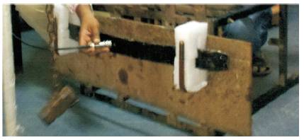
Figure 10. Test rig to hold Leaf Spring to measure vibrations
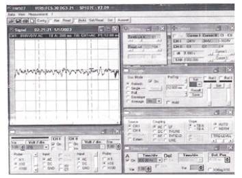
Figure 11. Oscillation Image captured from Hameg set (Volts Vs. Time) of the Metal leaf spring
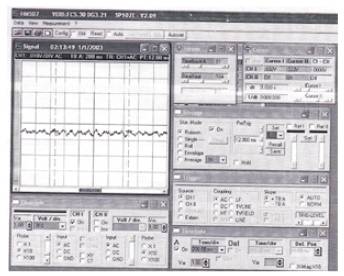
Figure 12. Oscillation Image captured from Hameg set (Volts Vs. Time) of the Composite leaf spring
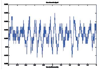
Figure 13. Free vibration oscillations measured using MATLAB of the Metal leaf spring
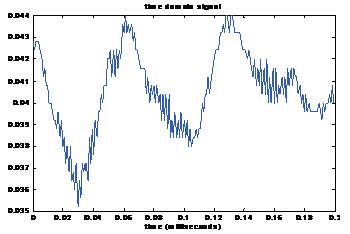
Figure 14. Free vibration oscillations measured using MATLAB of the Composite leaf spring
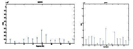
Figure 15. Harmonics developed from FFT analysis of a composite leaf spring
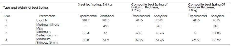
Table 4. Structural Analysis: Static Conditions
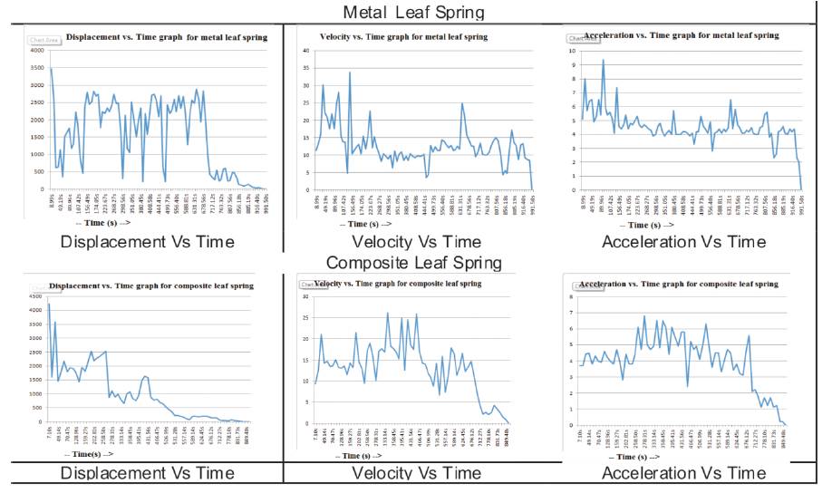
Table 5. Graphs generated from accelerometer for displacement, velocity and acceleration
The composite leaf spring with the same dimensions of steel leaf spring is analysed and the deflection is beyond the camber height and the stresses are beyond the permissible limits. The design is found to be unsafe and necessary changes in design are adopted. Calculations are made based on the design for same stiffness for the composite leaf spring which indicates a minimum of 12mm thickness to be maintained. A mono composite leaf spring of 12mm thickness and 100mm width is modelied and analysed. The results shows that the deflection observed is almost similar to that of steel leaf spring with reduced stresses leading to safe design. A composite leaf spring with 12mm thickness at the centre and varying (decreasing) thickness towards the ends is designed based on the beam of uniform strength and is analysed. The computed deflection is found to be more than the camber height and the induced stresses are not within the permissible limits. By trial and error process, the spring dimensions are redesigned with an increased thickness of 18 mm at the centre and corresponding variations in the the other sections until the induced stresses at centre are almost near to the stresses of composite leaf spring of uniform thickness. The weight of the steel spring is observed to be 26N, that of the composite leaf spring of uniform thickness is 17N and variable thickness is observed to be 18N. The weight is reduced by 34.6% and the leaf spring is deflecting nearly the same as that of steel leaf spring for the maximum load. The weight is reduced by 30% and the deflection of the composite leaf spring is very much smaller compared to steel leaf spring. The performance is higher than the steel leaf spring due the increase in damping capacity that exists inherently in composites.
1. Structural analysis is carried out on the steel leaf spring, and composite leaf spring with uniform and variable thickness. Composites have high stiffness (63 N/mm) as compared to steel leaf spring (51 N/mm). Approximately 30% weight reduction is observed in composite leaf spring as compared to steel leaf spring for same deflection characteristics.
2. The frequency harmonics measured using Hameg setup are compared with the natural frequencies developed using MATLAB code through Fast Fourier Transform (FFT) analysis. Steel leaf spring is found to have frequency of 18 Hz as compared to 22Hz of composite leaf spring.
3. Accelerometers results indicate that vibrations are subsiding faster in composite leaf springs (8 min) as compared to steel leaf spring (10 min).
Fatigue life cycles and random vibration analysis can be performed on variable thickness leaf springs and the same can be compared with metal and uniform thickness leaf springs.