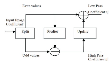
Figure 1. Block Diagram of Forward Lifting Scheme
In this paper, various types of VLSI architectures for image compression using Discrete Wavelet Transform (DWT) were reviewed. Images are the most convenient way of transmitting information. Compression is done to reduce the redundancy of the image and to store or transmit the data in an efficient manner. The DWT is popularly used due to its perfect reconstruction, multiresolution, and scaling property. The different architectures for convolution and lifting based schemes that are very much essential to design a new efficient hardware architecture for image compression are discussed. The DWT is the mathematical tool of choice, when digital images are to be viewed or processed at multiple resolutions. The signal compression and processing applications using wavelet based coding are of major concern.
In the era of information technology, the data compression is a powerful technology that plays a major role. The various types of data commonly transferred over networks, includes image and video data, which occupies more bandwidth(Parhi & Nishitani, 1993a) . With the demand for high quality video and image, there is a need for compression due to the limitations in the effective utilization of the available bandwidth and storage. So large video/images must be compressed and the same is reproduced without any degradation (Mallat, 1989).
Wavelet transforms a most powerful method to get the compressed images at higher compression ratios with higher PSNR values for Image compression applications (Parhi & Nishitani, 1993a). Wavelets allow complex information, such as speech, music, image, and patterns to be decomposed at different positions and using high precision reconstruction methods, it can be scaled into an elementary form (Sifuzzaman et al., 2009). Human vision system has low level characteristic, and to match this phenomenon, wavelet transform offers multi resolution image analysis (Parhi & Nishitani, 1993a; Parhi, 1991).
With the rapid growth of VLSI design technologies, implementation of the DWT on field programmable gate array (FPGA) has been widely developed. When compared to implementations of DWT on advanced RISC machines, DSPs, ARM processors, etc., FPGA implementation results in higher processing speed and lower costs (Parhi & Nishitani, 1993a).
The implementation of DWT has some issues with the complexity and needs extra memory for storing the computational results. DWT has to process large amounts of data at high speeds for real time image compressions. In some applications, the software implementation of DWT image compression provides flexibility for manipulation, but it may not meet some timing constraints (Sarala & Sivanantham, 2014). FPGAs provide a rapid prototyping platform. FPGAs are devices that can be reprogrammed to achieve different functionalities (Parhi, 1991). VLSI based designs are better choice for real time, low power, high reliability image compression applications. At present, many VLSI architectures for the DWT have been proposed to meet the requirements of real-time processing (Chakrabarti et al.,, 2015) .
The wavelet transform plays an important role in image processing, such as texture discrimination, audio compression, pattern recognition, computer graphics, etc. For image compression applications, wavelet transform is a more suitable technique. The multiresolution processing capabilities and also wide range of filter operations of wavelets are achieved with the help of advances in mathematics (Parhi, 1991; Chakrabarti et al., 1996).
The sub-band coding of wavelet Transform is used to yield a fast computation, which helps to reduce the computation time and resources (Parhi & Nishitani, 1993a). Images can be represented at different scales with local contrast changes with larger scale structures using wavelets (Parhi, 1991). The signal in DWT is represented using dynamic sub-band decomposition. The DWT based on time-scale representation provides efficient multi-resolution sub band decomposition of signals (Chakrabarti & Vishwanath, 1995). It offers better energy compaction than DCT without any blocking artifact. DWT divides the component into numerous frequency bands called sub bands as follows.
LL – Horizontally and vertically low pass
LH – Horizontally low pass and vertically high pass
HL - Horizontally high pass and vertically low pass
HH - Horizontally and vertically high pass
With the help of HPF and LPF, the input image is decomposed into high pass and low pass components giving rise to first level of hierarchy. The process is continued until multiple hierarchies are obtained.
From past several decades, many hardware designs are obtained for implementation of 1D/2D/3D DWT and IDWT for different applications. Majority of the designs are developed based on two categories, viz. (i) convolution based (ii) lifting-based. Most of the existing architectures are facing the difficulty with larger memory requirement, lower throughput, and complex control circuit (Mallat, 1989; Chakrabarti et al., 1996).
The circuit complexity can be explained with the help of arithmetic and memor y component. Arithmetic component includes adders and multipliers, whereas memory component consists of temporal memory and transpose memory. DWT filter length depends on the complexity of the arithmetic components (Srinivasarao & Chakrabarti, 2015). The size of the memory components depends on dimensions of the image.
Image dimensions are very high compared to DWT filter length due to the continuous increase in image resolutions from HD to UHD, so the complexity of the memory component occupies a major part in the overall complexity of DWT architecture (Srinivasarao & Chakrabarti, 2015).
In this section, VLSI architectures based on convolution method for hardware implementations of DWT are discussed. In this method of DWT, high pass and low-pass filter coefficients are derived in parallel.
The folded architecture uses one low-pass and one high-pass filter to execute the entire set of computation. Folding is defined as the process of executing many operations in one processor. This architecture uses minimum number of registers (Parhi & Nishitani, 1993a).
This has advantages of arbitrary word length, finergrained pipelining, and lower latency. Their drawbacks are increased hardware area, less constrained on speed; do not achieve complete hardware utilization, and complex routing and interconnection.
The digit serial architecture processes more than one bit, but not all bits of a word or sample. Digit size is referred as the number of bits processed per cycle if the digit-size is 1; the architecture called as bit-serial one, and bit-parallel if the digit-size is same as the wordlength. This can reduce the routing and interconnection cost and has better hardware utilization (Parhi & Nishitani, 1993a). The drawback is that it has more constraint on speed and the m wordlength must be in terms of multiples of 2 and has more system latency. This can be referred as a singleclock, nonuniform style architecture as it uses a single clock and the different wavelet levels are realized with different digit-sizes.
The Systolic architecture implements the Recursive Pyramid Algorithm (RPA). To compute the outputs of lowpass and highpass, it uses a linear systolic array and for computations of higher octave, inputs are stored in a storage unit. For the first octave computations, inputs are fed in alternate cycles to one end of the array, while the other required inputs are fed in parallel from the storage unit for the higher octave computations. The computations are done with a delay of 2N cycles.
This architecture implements the Modified Recursive Pyramid Algorithm (MRPA), which is a version of the RPA that is suitable for parallel filter. To compute the lowpass and the highpass outputs, the main components used are two parallel filters and a storage unit of size LJ. L fixed multipliers and a (L-1) adders to add the products are used in each parallel filters. The parallel filter latency is Tm + Ta log L, where Tm is the time taken to do a multiplication, and Ta is the time taken to do an addition. The storage unit consists of J serial in parallel-out shift registers, each of length L. For the ith octave computation 1 ≤ i ≤ J, the Ith shift register stores the inputs required.
For every 2i-1 cycles, an output is written into the Ith shift register and for every 2i cycles, all L elements of the shift register are fed to the parallel filters. The number of outputs of the Ith octave is half the number of outputs of the (i-1)th octave, the Ith shift register is clocked at half the rate of the (-1)th shift register. The MRPA scheduling determines the first output written time into or read out of a shift register. This includes 2(L-1) adders, JL storage units, 2L multipliers, and a control unit to generate the appropriate control signals. The period and computation time is N.
This architecture includes a parallel filter, systolic filter, and a bank of registers. It requires an area proportional to N L k and the computation has a delay of N2 + N cycles, the first output appears one cycle after the first input. The input samples are processed at the rate of one sample per clock cycle. For the computation of an N x N still image with a filter length L, this chip needs N2 + N clock cycles and N(2L-1) memory storage; for continuous picture such as video signal, its average computation time per picture spends about N2 only. This architecture significantly reduces the required memory space, the latency, the complex routing, and the hardware cost.
Image data is scanned single line at a time, which is line by line acquisition and is called as serial manner. The total number of lines stored in this architecture are minimum. When output coefficients are to be generated these are stored in the memory and these are not necessarily released. At a time only one line of an image is scanned by the encoder. Complete image scan is possible when all the lines are filtered before column filtering starts. For memory size order of the image, size is important. Let us assume X as the width of an image and L as the maximum length of a filter in a filter bank, so memory needed for filtering is 2L lines (Chrysafis & Ortega, 2000).
Wim Sweldens first introduced a method called lifting scheme for construction of wavelet (Chrysafis & Ortega, 1998). This scheme depends on the spatial domain, which has advantages, such as lower area, reduced computation, power consumption, and computational complexity. For construction of second generation wavelets, the lifting scheme emerges as a flexible tool. It is composed of three basic operation stages: split, predict and update (Daubechies & Sweldens, 1998; Sweldens, 1996). Figure 1 shows the forward lifting scheme of the wavelet filter.
Figure 1. Block Diagram of Forward Lifting Scheme
Split step: The signal is split into even and odd coefficients to obtain the maximum correlation between adjacent pixels for the next predict step. For each pair of given input samples x(n), split into even x(2n) and odd coefficients x(2n+1).
Predict step: The even samples are multiplied with the predict factor and then added to the odd samples to generate the detailed highpass filtered coefficients output (dj).
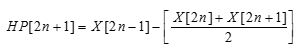
Update step: The predict step results are multiplied with update factors and then the results are added to the even samples to generate the detailed lowpass filtered coefficients output (sj) (Bhanu & Chilambuchelvan, 2012; Sowjanya et al., 2012).
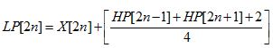
The inverse transform is obtained by exchanging the sign of the predict step and the update step and by applying all operations in reverse order as shown in Figure 2. The implementation of lifting based inverse transform (IDWT) is simple.
Figure 2. Block Diagram of Inverse Lifting Scheme
Using the three basic lifting elements as shown in below Figure 3 (Bhanu & Chilambuchelvan, 2012), the different types of lifting based DWT architectures can be constructed. The different types of DWT architectures are explained below.

Figure 3. Basic Functional Units of Lifting Schemes
This architecture is designed using multipliers, adders, delay elements, and pipeline registers. There are two lines in this one for even input samples and other one for odd input samples. Using basic processing elements, two pipeline stages are formed. The cascaded blocks are differing by multiplier's coefficients. The delay unit represented by z−1 is implemented by one register. Each delay unit contains two consecutive registers.
The parallel architecture can be designed using with K multipliers and (K-1) adders to add the products of the block. The computational delay in case of parallel filter architecture is Tm +Ta where Tm is the time taken to perform multiply operation and Ta is the time taken to compute adds operation. If it happens in single cycle, then RPA algorithm can be applied otherwise modified RPA (MRPA) algorithm is used for computation. MRPA is only the shifted version of RPA, where the shift is constant in order to not have conflicts in computation of wavelet levels (Chandra & Sharma, 2016).
Flipping means multiply the inverse coefficient for an each edge on the feed-forward cut-set; this can be done through the selected multiplier. As illustrated in Figure 4(c), each computation node can be divided into two adders, one can process in parallel with other computing units, and the other one is on the accumulative path. In addition to that multiplications on the same path can be merged together in order to reduce the number of multipliers count. For this simple example, the critical path is reduced to Tm +3Ta .
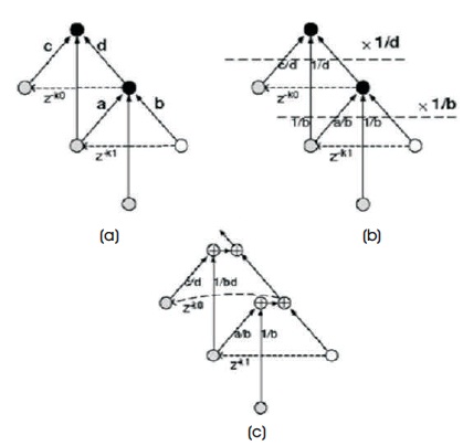
Figure 4. (a) Two Connected Computing Units (b) Flipping Computing Units (c) After Splitting Computation Nodes and Merging Multipliers
By flipping the original lifting-based architectures, the timing accumulation can be greatly reduced and no additional multipliers will be required. The low pass and high pass coefficients will be obtained by normalizing the flipping coefficients. There are also many alternatives for flipping structures. The number of computing units that should be flipped is dependent on hardware constraints.
In folded structure, the output is fed back through the delay registers to the input. The different wavelet structures are designed by adding different number of delay registers and coefficients. The speed of the internal processing unit depends on the even/odd input/output data. The data rate of the input/output DWT processor is one sample per clock cycle. This architecture requires 100% hardware utilization and the critical path in the multiplier can be reduced. The block diagram of folded architecture is shown in Figure 5.
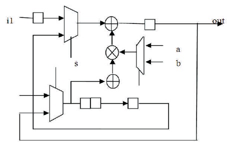
Figure 5. Folded Architecture
This computes the ith level of decomposition upon completion of the (i−1)th level of decomposition. For a finite-length input signal, the number of input samples is always greater than the total number of intermediate low-frequency coefficients to be processed at the second and higher stages (Bhanu & Chilambuchelvan, 2012). The same data path can be used to interleave the calculation of the higher stage DWT coefficients, while the first-stage coefficients are being calculated (Chrysafis &Ortega, 1998). The basic circuit elements used in this architecture is multipliers, delay elements, and MAC (Multiply-Accumulate) units, which are in turn designed using a multiplier, an adder, and two shifters (Jiang & Ortega, 2001).
A summary of the hardware resources and timing complexity of convolution and lifting based architectures has been presented in Table 1. An analysis has been performed with the latency, the hardware complexity, and internal memory size, and the timing performance has been described. This comparison provides to select appropriate method for selection of the best architectures with respect to their hardware and timing complexities.
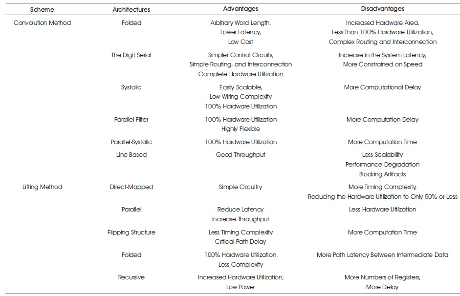
Table 1. Comparison of Various Architectures
In this paper, a detailed survey was to gain a better understanding of the properties of the existing different types convolution and lifting scheme discrete wavelet transform architectures based on the hardware complexities and computational time presented. The author have reviewed different architectures in order to better understand the different structures. This survey will be useful for exploring a new method of VLSI implementations using DWT architectures for application in image and video processing multimedia real time applications.