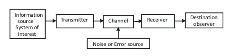
Figure 1. Generalized Measurement System
Enhancing the smartness of any electronic gadget or measuring system is highly encouraging. This article mainly focused on the design of a smart temperature transmitter for thermocouple. The transmitter consists of four functional block, viz. sensor module, signal conditioning unit (SCU), the processing unit and output module. The signals from thermocouples are fed to SCU for amplification and filtration of the thermocouple output. The proper amplified signal is now ready to be processed by a processing unit called a microcontroller. With the piecewise linearization technique, it computes the measured temperature and also performs the cold junction compensation using voltage from the IC sensor. Auto ranging logic is performed to generate 4 to 20 mA (milliampere) output signal for all thermocouples irrespective of their temperature range. The output module consists of a DAC, followed by a voltage to current converter and an LCD display panel for displaying various parameters or information. This design and fabrication work considers only three thermocouples (J, K, and T), but can accommodate upto seven thermocouples.
Industrial transmitters are the special type of measuring instrument used in industries to measure the physical values, such as temperature, pressure and flow measurements. The indications provided by the transmitter are read directly in the field or at the location of the fitted transmitter. The indications are sent in the form of a signal using cables or with wireless link to control equipment. Transmitter devices belong to the group of sensor, and traditional name of the device is “Transmitter” ( Cooper & Helfrick, 1985; Hordeski, 1985).
The electronic sensing instruments are assemblies of interconnected components that are organized to perform a specific function for analysis and synthesis, and are considered as an electronic system. The principle function of an electronic sensing, measuring instrument is the acquirement of data by detection and sensing, and the treating of that data ( Stanley, 2002).
The basic elements in a general measurement system (Figure 1) are: (i) Primary sensing element; (ii) Transducer element or variable conversion; (iii) Manipulation component; (iv) Data transmittance element; (v) Information processing component and (vi) Display or Data presentation ( Preobrazhensky, 1980).
Figure 1. Generalized Measurement System
Temperature is an intensive quantity independent of the size of the system. Temperature measurement depends upon the establishment of thermodynamic equilibrium between the system and the device used to sense the temperature. Temperature may be described as the “degree of hotness and coldness of a body or an environment measured on a definite scale” or “the measure of the mean kinetic energy of the molecules of a substance” or “a change in the temperature of the system accounts for the change in the molecular motion, hence it appears to be the kinetic energy of the molecules” ( Mulford, 1952; Preobrazhensky, 1980).
Thermocouples can measure extortionate temperature ranges with less expense. Thermocouples are very simple in construction. Thermocouple is widely used in industrial purpose as well as it can cope up with inflated temperature of industries, therefore, thermocouple is preferred over all other types of temperature sensors. The controlling of temperature range is very important for supremacy of components within test stations. This is how the electrical and mechanical maintenance is performed. Sensor technologies recommend basic types of temperature sensor such as RTD's, thermistors, integrated circuit (IC), mechanical thermometer, thermocouple etc. ( Preobrazhensky, 1980).
Extensive study, analysis and research work has been done in the field of temperature transmitter. Thermocouples are generally utilized for the measurement of temperature ranges between 0o to 1500oC because of their selfenergization. With minor calibration corrections, thermocouples can have accuracies of 0.25-0.5ᵒC. Mulford (1952) propose a method using two thermocouple junctions of opposing polarity, affixed next to each other in a current-carr ying conductor, to measure and compensate for the current-induced error.
Michalski et al. (2001) proposed research on measuring the temperature of solid bodies with a thermocouple and pointed out that temperature measurement of a solid surface has a series of possible errors, including temperature distortion error on the solid surface when introducing a thermocouple, and contact thermal resistance error between the solid surface and the thermocouple. Potter (1996) proposed that the national instrument SCXI, the signal conditioning system and low noise PC based DAQ system, when used to measure temperature through thermocouple, performance was excellent.
Volkow (2005) proposed that thermocouple readings could be affected by current in such a way as to add an “effect voltage” ΔU to the thermo-emf (electromotive force) of the thermocouple if it has direct contact with the current carrying surface. Authors concluded that the influence of current on thermocouple readings was a function of the voltage gradient along with the current carrying surface Bramley and Pickering (2006) conducted research on new Σ-Δ ADC with multi bit, PWM feedback which supplies both linearity and noise execution. This new technique enables the micro K products to perform in the DC (direct current) potentiometric instrument. Micro K replaces two instruments, i.e., Resistance Bridge and precision DVM (diel vertical migration) with the same capital and running cost.
Some researchers proposed low cost log amplifier based linearizing circuit for thermocouple temperature sensor. Log circuit cannot be applied to a very high temperature range. Computational as well as a PSPICE (Personal Computer Simulation Program With Integrated Circuit Emphasis) simulation technique have been carried out for different types of thermocouple other than G type because of its inflated temperature range, i.e., 1000ºC - 2300ºC. A few researchers proposed that J type thermocouple is linearized to a straight line in which the reaction was terminated, 100ºF-1000ºF by Quadratic Linearizing function AX+BX^2. Linearization is the transition that develops output corresponds to a linear alteration in input.
A hardware based method was proposed for the correction of thermocouple nonlinearity. It gives good results of linearizing signal from J and T type thermocouple. Thus, from this research, we acquire inexpensive cold junction compensation and linearizing circuit ( Aly & El-Lail, 2013). Kuri and Chattopadhaya (2014) presented a hardware based method for the correction of thermocouple linearization and J-type thermocouple responses with outrageous accuracy. It also constitutes a self-sufficient temperature measuring system with digital output.
From the review of literatures, it is obvious that a lot of work has been done to linearize the thermocouple output. For various input parameters, only limited type of thermocouple response are observed. Hence, few researches are reported on different type of thermocouples working together under a single linearization circuit. This type of temperature transmitter has various applications in industry, signal conditioning, auto detection of thermocouple, automation system, etc. Therefore, the design and fabrication of smart temperature transmitters have high potential for future work.
The objective of the research work is to design and fabricrate the smart temperature transmitter and the related objectives are:
A schematic diagram of smart temperature transmitter with the description of individual parts is given in Figure 2.
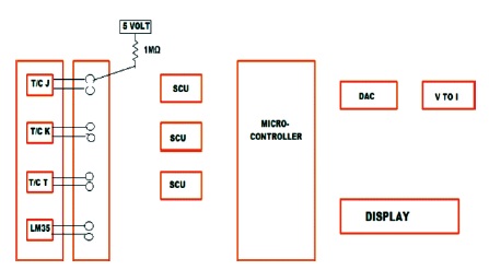
Figure 2. Schematic Diagram of Smart Temperature Transmitter
Sensor module is the very first part of this research work where the temperature is sensed with the help of thermocouples. There are many types of temperature sensing element, but the thermocouple is used for low range of temperature. In 1821, Seeback discovered the temperature measurement principle by thermo-electricity; it states that, when two conductors of dissimilar metals are coupled united to constitute a loop (a thermocouple), an electric current flows through the ring when two sufficient temperatures are imposed on the two interface connections. (Moffat, 1961; Preobrazhensky, 1980). The thermocouple characteristics are shown in Table 1.
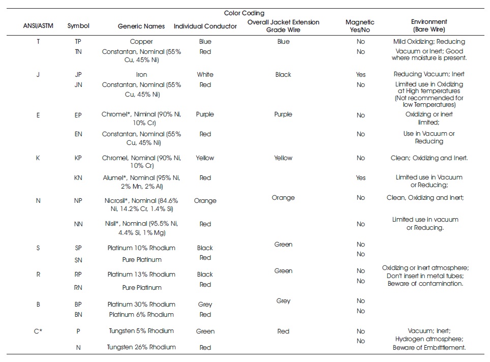
Table 1. Thermocouple Characteristics
The elements of a thermo-electric pyrometer are as follows:
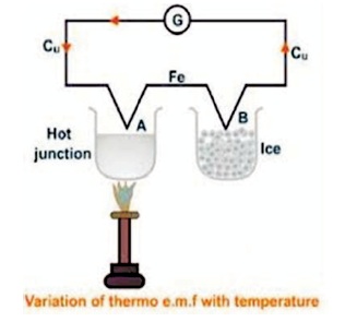
Figure 3. Thermocouple Arrangement
Characteristics of thermocouple materials are as follows:
The emf produced per degree of temperature change must be sufficient to facilitate detection and measurement. The emf of a thermocouple circuit is measured by equation (1),
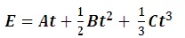
where, T - Temperature in °C; E - Reference junction temperature and A, B, C - Constant terms and dependent on the thermocouple material.
The greatest output for a thermocouple pair is obtained when one material is positive and the other is negative with respect to platinum. Sensitivity of a thermocouple is given in equation (2),
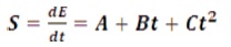
There are different types of thermocouples but in this experiment, we are working with J, K, R and T type thermocouples. These four types of thermocouples used in this work are described with their specification given below.
Type J (Iron/Constantan) Thermocouple: Type J thermocouple as shown in Figure 4(a) is used for the measurement of smaller temperature range (i.e., -346 to 1,400 F or (-210 to 760o C)) and it has a shorter lifespan at higher temperatures as compared to a Type K thermocouple. The standard accuracy of this thermocouple is ± 2.2o C or ± 0.75% and restrains of error is 0.4%. In terms of reliability and operating cost, it is equal to a Type K thermocouple.
Type T (Copper/Constantan) Thermocouple: The Type T thermocouple is shown in Figure 4(b), which is used in cryogenics, ultra-low freezers (i.e., extremely low temperature and stable temperature applications). The temperature range of this thermocouple is -454 to 700o F or -270 to 370o C. The standard accuracy of this thermocouple is ± 1.0o C or ± 0.75% and restrains of error is ± 0.5o C or 0.4%.
Type K (Ni-Chromium/Ni-Alumel) Thermocouple: The type K thermocouple as shown in Figure 4(c) has a wide temperature range; it is less expensive, reliable and accurate as compared to other types of thermocouples. The temperature range of this thermocouple is -454 to 2300o F or -270 to 1260o C. The standard accuracy of this thermocouple is ± 2.2o C or ± 0.75% and special limits of error is ± 1.1o C or 0.4%.
Type R (Platinum (Pt) Rhodium) Thermocouple: The R type thermocouple as shown in Figure 4(d) has higher temperature ranges, i.e., -58 to 270o F or -50 to 1480o C and it is used in high temperature applications. It is more expensive because of the higher percentage of Rhodium. It is highly accurate and reliable; therefore it is used often in lower temperature measurements. The standard accuracy of this thermocouple is ± 1.5ᵒC or ± 0.25% and restrains of error is ± 0.6ᵒC or 0.1%.
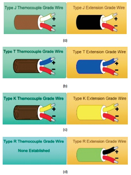
Figure 4. (a) Schematic of Type-J Thermocouple (b) schematic of Type-T Thermocouple (c) schematic of Type-K Thermocouple (d) schematic of Type-R Thermocouple
It is the communicating point between sensor module and signal conditioning circuits. In this junction box, one tap is used for Vcc (voltage common collector) connection, which is used for burnout protection. When thermocouple sensors experience disconnections, the receiving instrument indicates or records an incorrect value. The other tap is used for the output of each type of thermocouple, which is named as A, B, C, D respectively. It is fed to the control unit to produce two set points for multiplexer input for auto detection of thermocouple. The detailed junction box is shown in Figure 5.
Figure 5. Detailed Junction Box
The measuring instrument indicated and records the incorrect values when sensor experiences improper connection. To avoid disconnections and burnout situations, burnout detector is used. The burnout detection is illustrated in Figure 6.
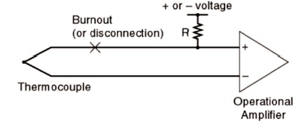
Figure 6. Burnout Detection
In this experimental work, functional amplifiers (ohmamps) are employed to conduct the amplification of the signal in the SCU phase. The full scale output of most sensing elements (i.e., sensors) is comparatively small voltages, currents or resistance changes. Therefore, their output must be properly conditioned before further analog or digital processing occurrence. An entire circuit is generally called a signal conditioning circuit as shown in Figure 7. SCU includes amplification, filtering, converting, range matching, isolation and other operations requisite to make sensor output suited for processing after conditioning ( Cooper & Helfrick, 1985; Fowler & Schmalzel, 2004; Hordeski, 1985).
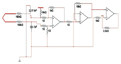
Figure 7. Signal Conditioning Unit (SCU)
The output of the first two inverting amplifier produces -10 and the ultimate non-inverting amplifier circuit produces 32 as a gain. This 32 input gain is calculated for a maximum temperature range of 1000 °C and the ADC input bit is 10, i.e., 1024 byte.
Vadc = 2.56V
LSB = 2.5 mV
Δe = (2.5/2) mV = 1.25 mV
Change per degree centigrade (minimum) = 0.039 mV
Gain = (1.25 mV/0.039 mV) = 32
The 10 bit ADC gives 0.5 °C resolution over 0 °C to 1000 °C range. Linear interpolation produces an error of less than 0.2 °C for a temperature span of 50 °C apart.
After the thermocouple output signal is filtered and amplified, it is then fed into the ADC port of the microcontroller. ATmega328 microcontroller unit is used in this project, which has inbuilt ADC and analog multiplexer for auto detection of the type of thermocouples as shown in Figure 8 ( Hordeski, 1985). The programming is made in such a way where the input type of thermocouple is understood with the help of an analog multiplexer bit. After the type is specified, it display the type of thermocouple which is ON and which are OFF. Next the program continues and it enters, reads the ADC input and stores in memory as J, K, T and I. After that the general Seebeck coefficient is stored in a particular type as Jc , Kc and Tc . Now it enters the while loop where the condition is provided for calculation according to thermocouple type. Lastly, the temperature is displayed after the Seebeck coefficient calibration.
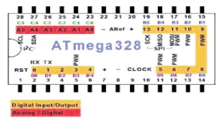
Figure 8. Microcontroller Atmega328 Pin Configuration
The ATmega328 is a dispirited-ability CMOS 8-bit microcontroller established in the AVR enhanced RISC architecture. It has inbuilt ADC and the pins are from pin23 to pin29. In this project pin23 to pin26 are used as ADC input. Pin27 and pin28 are used for DAC serial output which is interfaced with the external DAC MCP4725. Pin4, 5, 6 and 11 are used for interfacing the LCD display. The purposes of microcontroller programming are as follows:
ATmega328 microcontroller operates the temperature ranges from 40 ᵒC to 85 ᵒC. The operating voltage is used within the range from 1.8V to 5.5V and power consumption is at 1 MHz, 1.8V, 25 °C. The special features of this microcontroller are Power-on Reset and Programmable burn-out detection, Internal Calibrated Oscillator, External and Internal Interrupt Sources. It consists of 23 programmable I/O lines packages.
Features of Atmega328 pin configuration microcontroller are as follows:
In this last section, the analog signal is converted to digital with the ADC (analog to digital converter) used. The DAC (digital to analog converter) used in this project is MCP4725. The LCD used is JHD162A where the temperature and types of thermocouple are displayed (Bolk, 1985). The specification of the LCD and DAC are as follows.
Digital to analog converter (DAC): 12-Bit DAC with EEPROM Memory, the MCP4725unit as shown in Figure 9. It is less powerful, highly accurate, single channel, 12-bit buffered voltage output DAC with non-explosive memory (EEPROM). The two pin SDA and SCL are used for receiving the digital data to convert it into analog. Finally, the analog output is fetched at pin out. One ammeter is connected to the output of DAC to see the analog output.
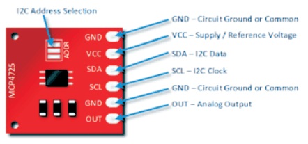
Figure 9. DAC (Digital to Analog Converter) MCP4725
Features: It consists of 12-Bit Resolution, Non-explosive Memory (EEPROM), Normal or Power-Down Mode, VDD i.e. external voltage reference and Rail-to-Rail Output. It uses the 2.7V to 5.5V single-supply for its functioning and the extensive temperature ranges are from -40 °C to +125 °C.
LCD module: LCD display screen is constructed in various standard forms. Commonly used sizes are two rows of sixteen characters 16×2. Alphanumeric LCDs may have a backdrop illumination, which might be LED, fluorescent, or electroluminescent. Alphanumeric LCD unit is shown in Figure 10. It utilize a 16 contact interfaces, generally utilizing pins or card edge associations on 0.1 inches (2.54 mm) focuses. Those without backdrop illuminations may have just 14 pins, overlooking the two pins driving the light. The ostensible working voltage for LED backdrop illuminations is 5V at full splendour, darkening at bringing down voltages subject to points of interest, for example, LED shading. Non-LED backdrop illuminations frequently require higher voltages. Pin 11, 12, 13 and pin14 are utilized for display input. The features that will be displayed are:
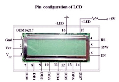
Figure 10. Pin Configuration of LCD
Features: It consists of 8-bit parallel number of data lines, LED (B/5.0V) backlight, single power driving method, 16 characters x 2 display construction and operate within the voltage of 0.3V to 7V.
c) Voltage to current (V/C) converter: This section is the ; last stages of this project where the output of the DAC is given as input to the V/C converter and we receive the current as final output. 0 to 5V is converted to 4 to 20 mA (milliampere) as the current output.
Microcontroller programming flow chart is illustrated as in Figure 11.
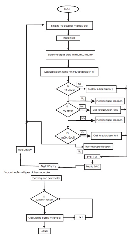
Figure 11. Microcontroller Programming Flow Chart
In the present experiment, we have used three types of thermocouple but we can use up to seven thermocouples for this equipment. In this, we have used 8- bit microcontroller for the programming which has inbuilt ADC (Analog-to-digital converter). At the beginning of the experiment, the input is read and initialized to a memory location as per the requirement. After that input is given to the circuit is stored in the memory location which would be used for comparison and calculation in future process. The room temperature (t) is then calculated with the help of LM35 and stored in memory with the variable name. Now, after reading each input, it is compared to 5v resistance which is used as the cut-off temperature to get the information about the burnout effect. During the experiment, we provide an input temperature equivalent to less than 5v. At the next stage, it automatically moves to the subroutine flow for further calculation. In the subroutine, the input is within the range. It will proceed further in a loop to calculate the temperature, (T ) with the 1 help of co-efficient ('mi' i.e. slope and 'ci' i.e., deflection). The coefficient values were calculated from the linear equation (y = m*x+c) for various temperature ranges and the values are stored in the memory location as mi and ci co-efficient. The calculated temperature in the subroutine is returned to the main program to calculate the final temperature. Therefore, the final temperature will be the summation of room temperature calculated (t) and the temperature returned from the subroutine (T ). This 1 final temperature, fed to the DAC (Digital to Analog converter), followed by the display unit which finally displays the temperature of the individual thermocouple. This transmitter allows three thermocouples of different types to be used simultaneously. If one thermocouple is in use, all the other thermocouples connected remain in cut-off mode. The process is repeated for various temperature measurement for each individual thermocouple used at different locations.
The design and fabrication of smart temperature transmitter is illustrated in Figure 12. The measured output values of signal conditioning unit (SCU) using Type J, Type K and Type T thermocouple are shown in Table 2, Table 3 and Table 4 with a different temperature range. The DAC (Digital to Analog converter) output values are also illustrated in Table 5 corresponding to the temperature input.
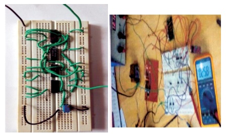
Figure 12. Snapshot of Smart Temperature Transmitter Circuit
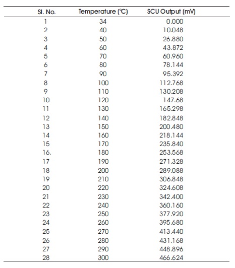
Table 2. Output Signal Conditioning Unit (SCU) for Type J Thermocouple at 34o C Room Temperature
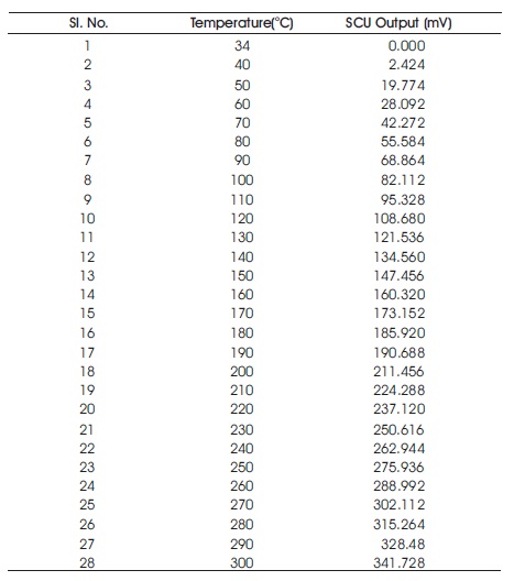
Table 3. Output of Signal Conditioning Unit (SCU) for Type K Thermocouple at 34o C Room Temperature
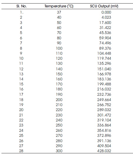
Table 4. Output of Signal Conditioning Unit (SCU) for Type T Thermocouple at 37o C Room Temperature
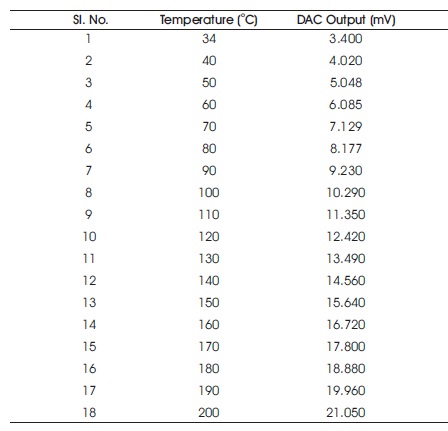
Table 5. DAC Output for Type J Thermocouple at 34o C Room Temperature
In the present design and fabrication work, the smart temperature transmitter with multiple thermocouple accessibility has been designed. Thermocouple J, K and T type are considered for this experimental work, but the transmitter can accommodate a maximum of seven thermocouples. Thermocouples outputs are filtered and amplified (gain=32) by Signal Conditioning Circuit. The output of Signal Conditioning Unit is acquired by the microcontroller (Atmega328) and further processing like linearization, and pole junction compensation, auto ranging has been met. The transmitter provides 4 to 20 mA output along with different display like thermocouple type, thermocouple open or burn out and thermocouple temperature.
After obtaining the measured values of the thermocouple at different temperatures, the final step is to confirm the experimentation (Kumar et al., 2019; Kumar & Bhatia, 2015a; Kumar & Bhatia, 2015b; Kumar & Dhanabalan, 2019; Kumar & Kumar, 2015; Mitra & Kumar, 2018). For the confirmation of the measured output values, we have used the multimeter instead of output device. This shows the output values equal to the measured values with minimum deviation.
The measured SCU linearization output for Type J, K and T thermocouple (at 34o C room temperature) are illustrated in Figure 13 and the measured DAC and SCU output for Type J thermocouple (at 34o C temperature) are shown in Figure 14.
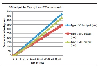
Figure 13. SCU Output for Type J, K and T Thermocouple
Figure 14. SCU and DAC Output for Type J Thermocouple
The aim of the experimental work is to design and fabricate a smart temperature transmitter for thermocouple with features like, Plug and Play for J, K, and T type of thermocouple, Burnout detection, Cold junction compensation, Output range set for 4-20mA and Digital display indicating temperature. The circuits for signal conditioning unit are designed and implemented. The gain is set manually and the output of the signal conditioning circuit is fed into the microcontroller for further analog to digital conversion. The converted output is then program med for auto detection of multiple thermocouples; burnt out detection/open thermocouple; auto calibration; auto ranging and displaying many outputs simultaneously. This output of the microcontroller is then converted from digital to analog signal. Thus the final output temperature is received and displayed in digital LCD. In the present experimental work, only three types of thermocouples are considered, but in future all the seven types of thermocouple may be used. In future, through programming, the style, colour and the LCD display can be modified with voltage to current, 4-20mA conversion can also be done.
The attained outcomes for smart temperature transmitter were tested by conducting a real experiment trail and found to be acceptable. This smart temperature transmitter may be used for the temperature measurement of three different medium/regions simultaneously, specifically insignal conditioning, auto detection of thermocouple, automation system steam boilers, IC (internal combustion) and CI (compression ingnition) engines, powder metallurgy driers for controlling of temperature at various stages, refrigerators, aerospace, defence and other industrial applications.
This manuscript represents valid work and the authors have no conflict of interests. Authors acknowledge that no funding has been granted/received for this research work and for the preparation of this manuscript.