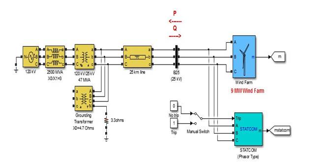
Figure 1. Wind Farm Model Connected to Grid
Renewable energy resources are the new generation challenges all over the world. The stochastic nature of these resources is considered as a barrier against using of them. This nature causes a lot of disturbances for power system operation. Also the stochastic nature of wind generation affects the power quality and the reliability of the system. FACTs devices are used in several researches to enhance the renewable energy generators specially wind generators to compensate its stochastic nature. In this paper, Shunt FACTs devices are used to enhance the dynamic response of voltage under the disturbance caused by wind generator. Proportional- Integral-Acceleration (PIA) as a new controller in this application is studied to enhance the performance of FACTs devices associated with renewable energy resources. Harmony Search Algorithm (HSA) optimization technique is used to tune the parameters of the controller. Finally, comparison of the PIA controller is carried out with the classical Proportional-Integral controller (PI) to verify the effectiveness of the PIA to enhance the power system operation with stochastic wind generator nature.
Nowadays all are talking about Renewable Energy Resources and how the best use of them can comfortably effect on an electrical power generation. It is known that electrical power generation came on two forms Nonrenewable methods like Electrical power generation using coal- Electrical power generation using oil- Electrical power generation using natural gas and renewable methods like Hydroelectric power generation - Wind electrical power generation - Solar Energy power generation - Wave electrical power generation - Geothermal electrical power generation. As the scale of renewable energy use in electrical power generation increasing with time it should be taken into consideration the main problems of renewable energy resources which are unpredictability and high variations in both output power and voltage and work on solving them.
There are different types of wind turbines such as: Fixed Speed wind turbines and Variable speed wind turbines[1] . Fixed speed wind turbines have simple control system, but very high variations in voltage profile and to overcome these very high variations, FACTs devices are connected to Wind turbine buses to control these variations. FACTs devices are power electronic devices used to take or inject reactive power to the grid to control system voltage within acceptable tolerance and increase power transfer capability[2, 3]. Most common used FACTs devices fixed speed wind turbines are static synchronous compensator (STATCOM) and Static VAR Compensator (SVC). These two devices have different principle of operation, characteristic operating curves [4], different installation cost [5, 6], and different control systems.
There are different types of controllers used to control devices in electric power systems, such as: Proportional- Integral controller (PI), Proportional-Integral Derivative (PID) Proportional-Integral-Acceleration (PIA), and Proportional- Integral-Derivative-Acceleration (PIDA) [7, 8].
Optimization techniques are used to tune the controller parameters. Tuned parameters have better transient, dynamic and static response. There are many types of optimization techniques used in tuning controllers as Genetic Algorithm (GA) [9], Tabu Search (TS) [10], Particle Swarm Optimization (PSO) [11], Gravitational Search Algorithm (GSA) [12], Teaching Learned Based Optimization (TLBO) [13], and Local Harmony Search Algorithm (HSA) [14].
As wind power generation scale is increasing, voltage stability limits represent a point of study as in [15] . Authors of [16] showed that FACTS impact on power systems connected with wind farms. In [17], authors reported how voltage recovers in grid connected wind turbines after a short circuit fault. In [18], it is reported that STATCOM can recover terminal voltage of Squirrel cage induction generator after fault clearance, so it is used to improve transient and dynamic stability of fixed speed wind power generation systems with Squirrel cage induction generators by compensating the reactive power. In [19], SVC is reported that it can also be used to improve terminal voltage of induction generators. When using Induction generators as a wind generator, its necessary to check stability of induction generates as in [20]. In [21], authors have reported valuable studies on STATCOM connected with wind turbine generators. In [22], stability of fixed speed wind turbines was discussed using a two level VSC-STATCOM and a fuzzy controller system used as controller to STATCOM. In [23], an application of SVC to mitigate voltage instability in a grid wind system is reported. In [24] and [25], authors made a comparison between SVC and STATCOM for wind farm integration.
In this paper, comparison between optimized PIA and default PI controllers are carried out in case of SVC and STATCOM to enhance dynamic voltage profile. After that comparison between SVC and STATCOM through tuning parameters of PIA controller is carried out. Results showed that the SVC will give better voltage profile in dynamic voltage response and enhance operation of fixed speed wind turbines with less complex controller than STATCOM. The Harmony search algorithm is used to tune the PIA controller in both SVC and STATCOM.
MATLAB Model of a fixed speed wind farm model with 9 MW capacity connected to grid is used in this paper. The model name is "power_wind_ig" as shown in Figure 1. A 3 MVA STATCOM is connected to wind farm bus to control voltage profile. The wind farm is represented by 3 wind turbines as prime mover to induction generators. The transferring of wind speed into electrical power is through MATLAB Simulink block shown in Figure 2. Each wind turbine has 3 MW capacity and 10 m/s base wind speed. Here the linearized estimated wind speed profile as in Figure 3 is used as input to the three wind turbines to study dynamic voltage at wind farm bus.
Figure 1. Wind Farm Model Connected to Grid
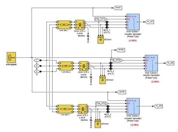
Figure 2. Wind Farm Electrical Connections
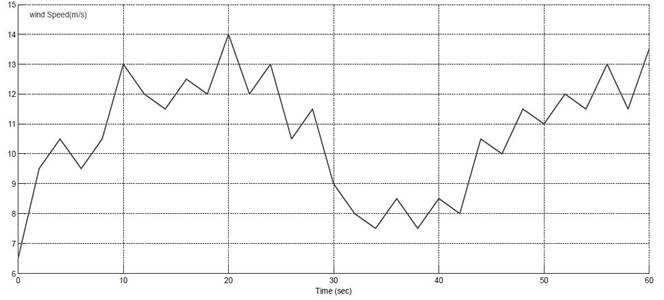
Figure 3. Linearized Estimated Wind Speed Profile
The AC-Voltage regulator control circuit of SVC and STATCOM will be modified through replacing the (PI) controller circuit by (PIA) controller circuit. Tuning the parameters of (PIA) circuit is carried out by using Harmony- Search optimization technique for better voltage dynamic response of wind farm voltage profile. PIA-SVC response will be compared with default PI-SVC response then comparing PIA-STATCOM response with default PI-STATCOM. Finally, response of PIA-SVC and PIA- STATCOM with same ratings (3 MVA) is compared.
In the PI controller, error signal is multiplied by proportional term gain and the integration of error is multiplied by the integral term gain (Kp , Ki), respectively. The result is added to give controller output signal as shown in Figure 4. Transfer function equation of (PI) controller is as shown in equation (1). For the controller is better performance, the two designing parameters which are Kp and Ki should be tuned.
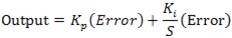
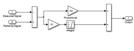
Figure 4. PI Controller Circuit
PIA controller is a modified model of the PIDA controller which given in [26], but with omitting the D controller parameter from the model. The circuit of PIA as shown in Figure 5 consists of Proportional gain Kp, integral gain accelerating gain Ki, and filter elements (d, e). PIA controller i transfer function equation is given in equation (2); Where O = e+d, M = e*d. The PIA controller has five designing parameters which are (Kp, Ki, Ka, O, M).

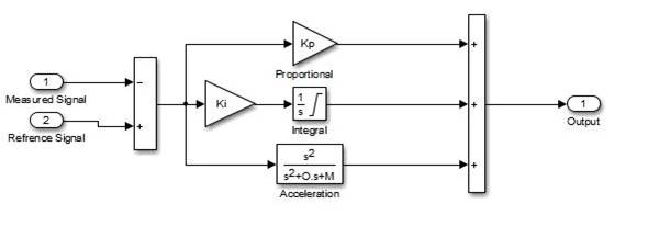
Figure 5. PIA Controller Circuit
As shown in Figure 6, firstly wind bus per unit voltage is measured and added to the system droop voltage due to SVC characteristics slope reactance (Xs) and then subtracted from reference voltage which equal 1p.u. The result value is the error signal (E) which is multiplied by controller transfer function. The closed loop time constant (Tc) is taken as (10-4) second. Output of controller will be per unit susceptance (B) as in equation (3). The only difference between SVC with PI- Voltage regulator circuit and SVC with PIA Voltage regulator circuit is the accelerating term with gain Ka and filter elements O = e+d, M=e*d. Default PI- SVC has Kp = 0 and Ki = 300.
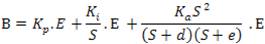
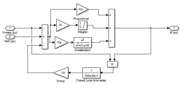
Figure 6. SVC PIA Voltage Regulator Control Circuit
As shown in Figure 7, the PI-AC Voltage regulator circuit is changed into PIA-AC Voltage regulator circuit. Output of controller will be the Reference value of quadrature-axis component of current flowing into STATCOM(Iqref) as in equation (4). The difference between STATCOM with PI-AC Voltage regulator circuit and STATCOM with PIA-AC Voltage regulator circuit is also the accelerating term with gain Ka and filter elements O = e+d, M = e*d.
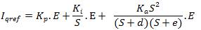
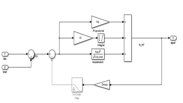
Figure 7. STATCOM PIA - AC Voltage Regulator Control Circuit
Sequential steps of Harmony Search Algorithm to optimize the controller designing parameters are [14] :
1. Initialize
 (bi is used).
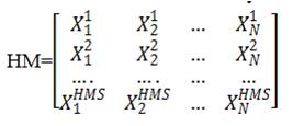
2. Initiation of Harmony Memory (HM)
3. Improvisation: Generation of new harmony is based on the following criteria.
4. Harmony Memory is updated by removing the worst harmony for objective function minimization.
5. Above steps is repeated till maximum iteration is reached and optimum solution is obtained.
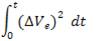
The objective function is to minimize the integrated square of error of per unit wind farm terminal voltage which means better dynamic response. Objective function equation will be as shown in equation (8).
Harmony Search algorithm is used to design variables of the (PIA) controllers to minimize the objective function and their ranges used for PIA-SVC will be:
0 ≤ Kp ≤ 30, 350 ≤ Ki ≤ 600, 10 ≤ Ka ≤ 200, 650 ≤ (e+d) ≤ 1100, 650 ≤ (e*d) ≤ 1100.
Ranges used for PIA-STATCOM (with PIA ac voltage regulator circuit) to minimize the objective function will be:
0 ≤ Kp ≤ 150, 750 ≤ Ki ≤ 1500, 10 ≤ Ka ≤ 200, 650 ≤ (e+d) ≤ 1100, 650 ≤ (e*d) ≤ 1100.
Harmony Search Algorithm will be used to optimize the controller design parameters. The objective of the optimization is to get the least integrated square error. The operation of the optimization is as shown in Figure 8.
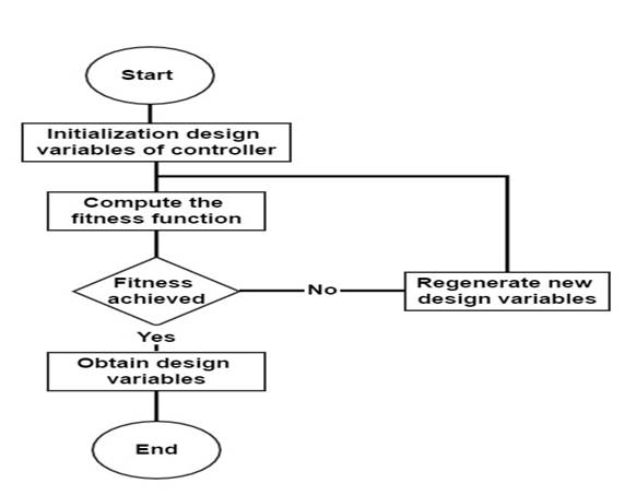
Figure 8. Methodology Flowchart
After using HSA to optimize the five design variables for both PIA-SVC and PIA- STATCOM to minimize the objective function, the results are as shown in Table 1. The results showed the superiority of SVC than STATCOM. Figure 9 shows that wind farm dynamic voltage will be better when using same 3MVA-SVC, but with optimized PIA voltage regulator circuit. The minimum terminal voltage using PIA-SVC is 0.9658 p.u, but for default PI-SVC is 0.9618 p.u at time 10.33 seconds. Figure 10 shows optimized STATCOM with PIA-AC Voltage regulator circuit has poor improvement than default STATCOM with PI-AC Voltage regulator circuit. The minimum terminal voltage of PIA-STATCOM is 0.9645 p.u and for default PI-STATCOM is 0.964 p.u at time 10.32 seconds. Figure 11 represents comparison between optimized PIA-SVC and optimized PIA-STATCOM. Results show optimized PIA SVC has slightly better dynamic performance. Minimum terminal voltage of optimized PIA-SVC is 0.9658 p.u, but for optimized PIA-STATCOM is 0.9645 p.u.
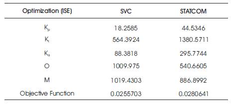
Table 1. HSA Optimization Results
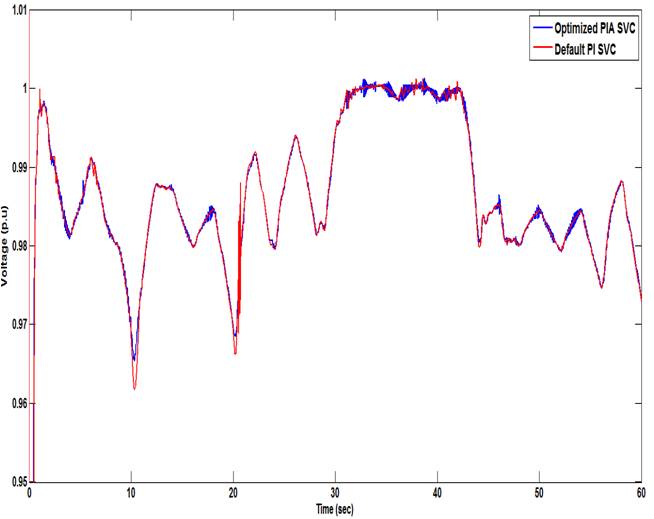
Figure 9. Wind Farm Dynamic Voltage using Default PI-SVC and Optimized PIA-SVC
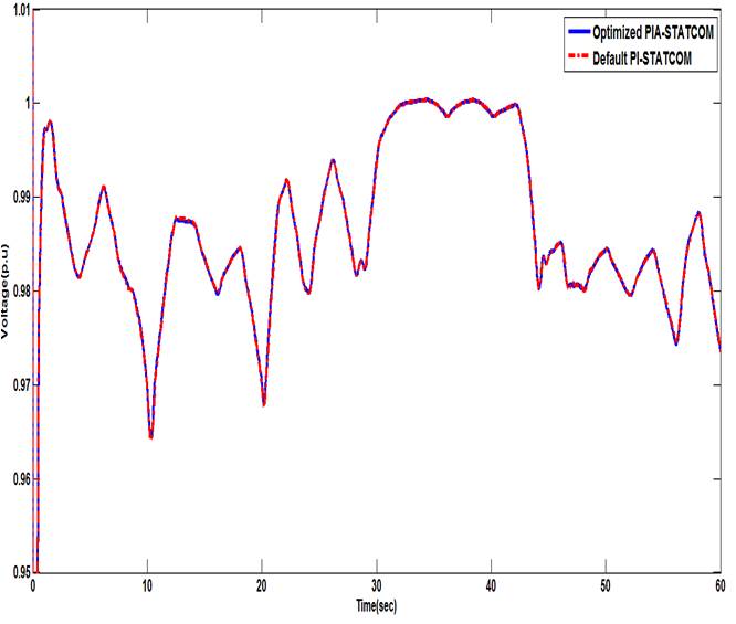
Figure 10. Wind Farm Dynamic Voltage using Default PI-STATCOM and Optimized PIA- STATCOM
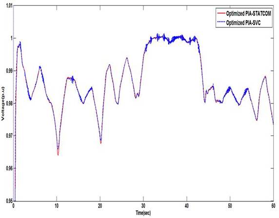
Figure 11. Comparison between Optimized PIA-SVC and PIA-STATCOM
For enhancing Operation of Fixed speed wind turbines, new modification of AC voltage regulator circuit for both SVC and STATCOM will be helpful. Also as shown in results PIA modified SVC has slightly better performance in dynamic voltage response than optimized PIA STATCOM with lower installation cost. New modified PIA-SVC has clearly better performance than default PI-SVC, especially at high rate of variation of wind speed. For better improvement of STATCOM, one should change the two remaining PI controller circuits in STATCOM control system which are (DC Voltage regulator circuit) and (DC Current regulator circuit) into optimized PIA controller circuits.