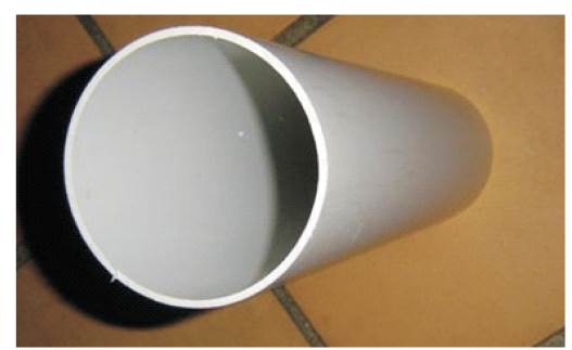
Figure 1. A PVC Pipe
This paper deals with maximizing the power output from wind turbines over, all the expected wind conditions, while minimizing construction costs. The wind turbine construction is complex due to the design of turbine blades. As such, the authors focus on minimizing the amount of materials required to make the blade, while maximizing the power output. The considered disciplines include, aerodynamics, structures, and control. By considering a range of incoming wind velocities that represents the possible operating conditions of the turbine, the expected power output and extreme structural load over this range can be calculated. To Further limit the design space, the authors made a three-bladed design with PVC (Poly Vinyl Chloride) blades. The authors choose three blades, because, an initial Design of Experiments (DOE) test showed that, the three blades’ performance and efficiency is higher than the four and five-bladed designs in almost all cases. The traditional wind turbine’s cut in speed is 4 m/sec and so, the authors are trying to design a turbine that starts producing power even at a wind speed of 3 m/sec. Designed and fabricated wind turbine with a control system allows it to direct the blades against the wind flowing direction.
Blade design and engineering is one of the most complicated and important aspects of current wind turbine technology. Engineers strive to design blades that extract much energy from the wind as much as possible in a variety of wind speeds, while remaining durable, quiet and affordable. This engineering process requires a great deal of scientific experimentation, modeling, and testing. With some simple materials and a bit of creativity, you can experiment with advanced concepts in the wind turbine blade design, including airfoil shapes and twisted-pitch blades.
In recent years, wind energy has drawn more attention due to the increasing prices of fossil fuels and improving economic competitiveness of wind turbines relative to conventional generation technologies [1]. Today, wind energy has been developed into a mature, competitive, and virtually pollution-free technology. Usually a typical large, utility scale wind turbine can produce 1.5 to 4.0 million KWH annually and operates for 70-85% of the time. Global wind energy production set a new record in 2011, reaching 239 GW in 3% of total electricity production. It is predicted that, by 2020, it will increases to 10% of global electricity production.
In a macro-meteorological sense, winds are the movements of air masses in the atmosphere mainly originated by temperature differences. The temperature gradients are due to uneven solar heating. In fact, the equatorial region is more irradiated than the polar ones. Consequently, the warmer and lighter air of the equatorial region rises to the outer layers of the atmosphere and move towards the poles, being replaced at the lower layers by a return flow of cooler air coming from the Polar Regions. This air circulation is also affected by the Coriolis forces associated with the rotation of the Earth. In fact, these forces deflect the upper flow towards the east and the lower flow towards the west. Actually, the effects of differential heating dwindle for latitudes greater than 30°N and 30°S, where westerly winds predominate due to the rotation of the Earth. These large-scale air flows that take place in the entire atmosphere constitute the geotropic winds.
The lower layer of the atmosphere is known as surface layer and extends to a height of 100 m. In this layer, winds are delayed by frictional forces and obstacles altering not only their speed, but also their direction. This is the origin of turbulent flows, which cause wind speed variations over a wide range of amplitudes and frequencies. Additionally, the presence of seas and large lakes causes air mass circulation similar in nature to the geotropic winds. All these air movements are called as local winds.
A winglet is a small attachment at the tip of the blade which has the same cross section as the blade. The purpose of attaching the winglet to wind turbine blades is to decrease the total drag from the blades and to increase the aerodynamic efficiency of the turbine. The design of winglet optimizes the drag reduction, maximizes the power production and minimizes the thrust increases. In 1970s, Richard Whitcomb first invented the winglet concept for aircrafts to decrease the drag and increase the lift. The provision of winglet for aircrafts yielded a 7% increase at cruise speeds [2]. Subsequent research conducted by Peter Masak of the Soaring Association of Canada, has yielded substantial insight into the optimization of the size of winglets for low-speed applications [3]. The parameters considered for the design of a winglet are its height, sweep angle, cant angle, curvature radius, toe angle and twist angle. The winglet concept improves the performance of wind turbine system as predicted in Risø DTU National Laboratory using computational fluid dynamics.
The objective of this research project was to design, fabricate and test a new blade for a small wind turbine. To reach this goal, the following sections were completed:
To utilize the available wind resources and to reduce the usage of non-conventional sources of energy resources. Wind energy is the fastest growing renewable energy resource. The wind energy industry so far has been supported by market incentives backed by government policies fostering sustainable energy resources.
Large-scale wind facilities are approaching the output rating of conventional power plants, hence control of the power quality is required to reduce the adverse effects on their integration into the network. These wind turbines can be utilized to provide constant lighting. In most cities, bridges are a faster route for an everyday commute and in need of constant lighting makes this as an efficient way to produce natural energy [4].
This design methodology is to increase the efficiency of the windmill and firstly, the designing steps starts with the design of windmill blades, as these blades mainly affect the overall efficiency of the windmill[6]. For a particular application, the windmill blade should be in a required size. According to aerodynamic style, the windmill blade design is very much important in order to get full efficiency. The considerations are given as follows.
The speed of the wind is very much important for the production of electricity in the windmill, because, in windmills, the wind is used as a raw material for the power production. This bakes the axis rotation which is coupled with a DC generator, which produces electricity by mean of rotation.
The height of the tower is very much important for a windmill. In HAWT (Horizontal Axis Wind Turbine), the tower is kept, 3 times as the rotor diameter to increase the whole air density passing from the vehicle. We should concentrate in the design of the tower because, it should be able to withstand its own weight and also the speed of wind.
As discussed earlier, the shape of the windmill blades is the important one if one could place an efficient design of a blade, then the efficiency of the windmill will be increased.
This tip speed ratio defines the speed of the wind that hit the tips of the blades and makes a rotation. In this speed, the blade will give you a good performance. When the tip speed ratio increases, the productivity of the windmill also increases.
Blade Design and Engineering is one of the more complicated and important aspects of current wind turbine technology. Engineers strive to design blades that extract much energy from the wind as much as possible in a variety of wind speeds, while remaining durable, quiet and affordable. This engineering process requires a great deal of scientific experimentation, modelling and testing [7]. With some simple materials and a bit of creativity, we can experiment with the advanced concepts in wind turbine blade design, including airfoil shapes and twistedpitch blades.
For designing the blades, the authors have used a PVC pipe of Ø180 mm with a length of 880 mm and it is having a thickness of 4 mm with a tensile strength of 4kg/cm2 as shown in Figure 1.
Figure 1. A PVC Pipe
3 blades can be made from a 4 ft long pipe. First, cut the pipe into four equal quarters and then mark the dimensions as shown in Figure 2.
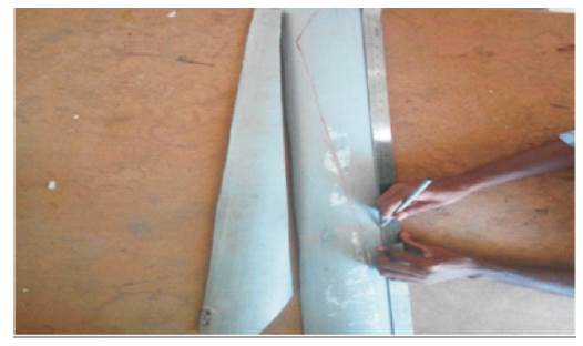
Figure 2. Marking Dimensions on PVC Pipes
For the design of frame, the material selection is very much important. Because, the material that we are selecting should be as heavy as it should able to withstand high air pressure. For that, a special grade of MS steel can be used, as it is lightweight and it can able to withstand high air pressure. The shape of the frame used is shown in top and front views in Figures 3 and 4 respectively.
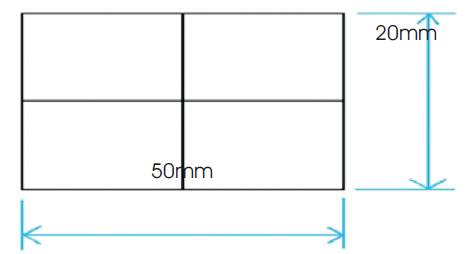
Figure 3. Top View of the Frame
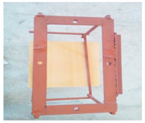
Figure 4. Front View of the Frame
For the design of a blade, the material selection is very much important. Because, the material that we are selecting should be more weight less and able to withstand high air pressure. For that, a special grade of PVC plastic can be used, which is lightweight and can withstand high air pressure. The next important thing is to choose a blade shape. The C-type blade is suitable for Vertical Axis Windmill (VAW), because, its shape can collect maximum air pressure and give maximum energy transformation from the forced wind energy into rotational mechanical energy. The shape of the blade used is shown in Figure 5.
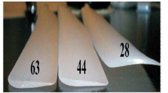
Figure 5. Views of Blade
The horizontal Axis Windmills normally have 3 blades that are placed in the tangential direction of the hub. These 3 blades were normally separated with each other by 120- degree angle. So that, when the wind passes the HAWT, it will rotate in the clockwise direction.
The wind turbine blade design has been decided and now the blades must be fixed to build the turbine arrangement of the blades and its rotating directions are shown in Figure 6.
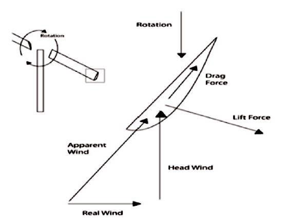
Figure 6. Diagram of Blade Rotation
The hub is the support for the turbine blades to rotate. For the design of hub, the selection of material is very much important, as, the material that we are selecting should be tougher and able to withstand high pressure. For that, a special grade mild steel sheet having a thickness of 4 mm is used, which has light weight and can able to withstand high air pressure and high loads. The Hub material used is shown in Figure 7.
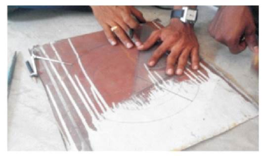
Figure 7. View of Marking Dimensions on MS Plate
For the design of tail also, the selection of material is very much important. A special grade Aluminium used which is lightweight and can able to withstand high air pressure. The length of the tail should be 2/3 of its rotor diameter. The shape of the wind guide used is shown in Figure 8.
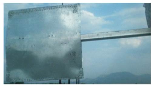
Figure 8. Side View of Wind Guide
The arrangement should be made at the back of the nacelle as shown in the Figure 8, so as to rotate the turbine rotor towards the wind flowing direction.
The alternators or generators are the heart of windmill and it must be properly sized to match your swept area and to produce right type of power to match the application. The unit needs to make higher voltages at lower rpm, otherwise it is not suited for wind power use, even motors can also be used as generators. In this vertical axis highway windmill, the authors have used two DC generators coupled with the wind blade turbine.
Wind generators come in various voltages such as, 12 volts, 24 volts and 48 volts DC and in a range of currents up to 80 amps at 12 volts. The wind generator is a square torque machine and the output increases exponentially with the increase in wind speed. Most quality wind generators come with a blade stall facility that “stalls” the blades at a high wind speed. An electrical blade lock that locks the generator on throw by a switch. This prevents the generator turning, while servicing in its progress. Wind generator technology is a very mature technology and has been used for atleast past 20 years. The technology is reliable and reasonably priced. Maintenance of a wind generator is simple, just grease the front and rear bearings and check all bolts and connections on a basis. Wind generators are capable of producing large amounts of current, upto 80 amps at 12 volts and should always be fitted with a charge controller containing a power dump system. Wind Generators are a cost efficient way of producing power using a sustainable energy force of the wind. They can be easily indicated into a Hybrid Power System and also works well with solar arrays. The solar array controller can also be used by the wind generator to control and dump any excess power produced by the hybrid system. If the sun does not shine hopefully, the wind will be blowing yearly. Figure 9 shows the PMDC Generators used in windmills.
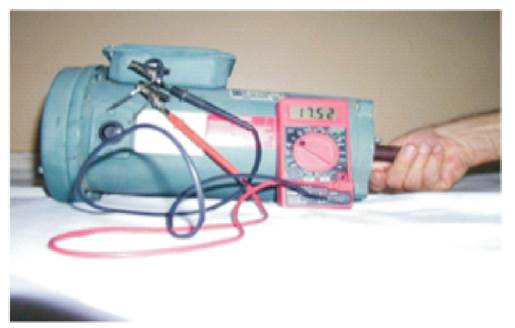
Figure 9. Normal PMDC Generators
This is the wind speed at which the rotor starts turning. It should spin smoothly and easily when you turn it by hand, and keep spinning for a few seconds. Designs that “cog” from magnetic force or that use gears or pulley to increase shaft speed will be poor at the start up. The proposed design can start spinning from 3 m/sec winds cut in at 10 m/sec.
Every generator has certain speed, at which it runs more efficiently. But since the wind is not constant, we must try to design to the required medium. As the wind speed rises, the raw power coming into the generator from the wind becomes more than the generator can effectively use, and it gets more and more inefficient. This power is wasted as heat in the stator coils.
A one-stage gearbox has only one gear reduction, which can be used to adjust the angular velocity of each blade rotor to the contra-rotating generator. If the blade of the rotors rotate at the correct angular velocity, a one stage drive train could be used to add the torques together for a normal low speed, high torque, and PM generator. For either case, the drive train can be made up of a gear, chain, or belt system.
A simple gear system that has a driven gear and a driving gear is shown in Figure 10. For the manufacturing of gears, the selection of material is very much important, because, the material that we are selecting should be tougher and it able to withstand high torques. For that, a special grade of Aluminium can be used, which is lightweight and it able to withstand high torque.
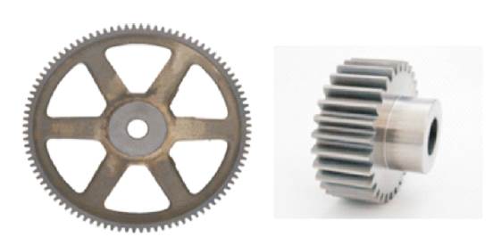
Figure 10. Views of Gears
Diameter - 240 mm.
Height - 350 mm.
Width - 200 mm. .
Breadth - 500 mm.
Height - 1140 mm.
Rotor Diameter - 2133 mm.
Length - 914.4 mm
Width - 40 mm
Driving gear outer diameter - 227.5 mm.
Driven gear outer diameter - 32.5 mm.
Module - 1.25.
Various operations are involved in the fabrication process of horizontal axis wind turbine.
The following are the fabrication techniques involved
1. Circular saw cutting (Figure 11)
2. Arc welding
3. Drilling
4. Metal painting
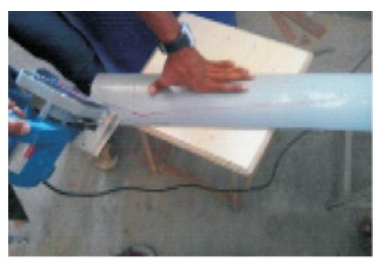
Figure 11. Circular Saw Cutting
The windmill works on the principle of converting Kinetic energy of the wind into Mechanical energy. The kinetic energy of any particle is equal to one half its mass and square of its velocity, or ½ mv2 .
K.E = Kinetic Energy,
M = Mass,
V = Velocity.
M is equal to its Volume multiplied by its Density ‘ρ’ of air

Substituting equation (2) in equation (1) we get,
where,
ρ = Density of air (1.225 kg/m3)
A = π D2 /4 (Sq.m)
D = Diameter of the blade
A = π*(2.13)2 /4
A = 3.56 Sq.m
Available wind power Pα =
(½ρπD2 V3 )/4
P = 1/8ρπD2V3
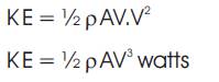
Figure 12. Horizontal Axis Wind Turbines
A preliminary budget of Rs.20, 000 has been set. The main cost includes, the Aluminium gears (Rs.1500), PVC plastic pipe (Rs.650), PMDC Generator (Rs.6400) and MS Pipe (Rs.2000). Other minor items, such as setscrews, bolts, nuts, and washer were obtained at a low cost.
By considering all the factors that influence the performance of a wind turbine, it is clear that the designed blades with PVC material, can withstand high pressure winds and reduce the losses that occur due to the self weight of the rotor. By the construction of blades with PVC material, the cut-in speed of the turbine can be reduced to 3m/sec at which it is able to produce power consistently without any interruptions even at low wind speed conditions. With a small change in blade angles, we can extract higher amount of power from the wind. As fossil fuels are extinguishing, it's time to concentrate more on the developing technologies associated with the usage of renewable energy sources.