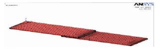
Figure 1. Meshed model of Bonded Joint
The composite structural members are highly used in the following applications such as aerospace, automobiles, robotic arms, architecture etc., has attracted extensive attention in the past decades. One of the important issues in the composite technology is the repairing of aging aircraft structures. In such applications and also for joining various composite parts together, they are fastened together either using adhesives or mechanical fasteners. Modeling and static analysis of 3-D models of the joints (bonded, riveted and hybrid) were carried out using ANSYS 11 FEA software. The results were interpreted in terms of Von Mises stress. A parametric study was also conducted to compare the performance of the hybrid joint with varying adherent thickness, adhesive thickness and overlap length. To utilize the full potential of composite materials as structural elements, the strength and stress distribution of these joints must be understood. ANSYS FEA tool has been performed to investigate the stress distribution characteristics of various configurations of single lap joint. This study was focused on the analysis of stress distribution in three prominent joining methods namely, bonded, riveted and hybrid joints. FEA is used to study the stress distribution in the members involved under various design conditions and various joints failure criteria.
Over the past three decades, application of composite materials are continuously increasing from traditional application areas such as military aircraft, commercial aircraft to various engineering fields including automobiles, robotic arms and even architecture. Due to its superior properties, composites have been one of the materials used for repairing the existing structures. In such applications and also for joining various composite parts together, they are fastened together either using adhesives or mechanical fasteners. Nowadays, a novel method called hybrid joint is also being employed, where a combination of both adhesive and mechanical fasteners is used.
In the present project, an attempt is made to analyze the stress distribution in 3-D models of three configurations of single lap joint, namely, bonded, riveted and hybrid joints. A parametric study of hybrid joint, by varying the dimensional parameters of the joint was also conducted.
Modeling and static analysis of 3-D models of the joints (bonded, riveted and hybrid) were carried out using ANSYS 10 FEA software. The results were interpreted in terms of Von Mises stress. A parametric study was also conducted to compare the performance of the hybrid joint with varying adherent thickness, adhesive thickness and overlap length.
Ideally, it is always preferred to make monolithic structures, that is, structures without joints. This ideal can never be realized for many reasons like size limitations imposed by materials or the manufacturing process, need for disassembly of structure for transportation and access for inspection and repair etc. Basically, there are two types of load-carrying joints available: mechanically fastened joints and adhesively bonded joints [1]. Nowadays, a novel method called hybrid joint is also being used in certain applications.
Bonded joints can be made by gluing together pre-cured laminates with the suitable adhesives or by forming joints during the manufacturing process, in which case the joint and the laminate are cured at the same time (co-cured). Here, load transfer between the substrates take place through a distribution of shear stresses in the adhesive [1] (Figure 1).
Figure 1. Meshed model of Bonded Joint
Riveted joints can be used quite successfully on laminates up to about 3mm thick and also where a tight fit, called interference fit, is necessary. The choice lies between solid and hollow types and whichever is chosen, care must be taken to minimize damage to the laminate during holedrilling and closing of rivet [5]. The holes create stress concentration and reduce the strength of the substrate laminates. Other than this, these joints incur a large weight penalty and also create a potential corrosion problem resulting from contact with the composites. Also disassembly is not possible in riveted joints [2] (Figure 2).
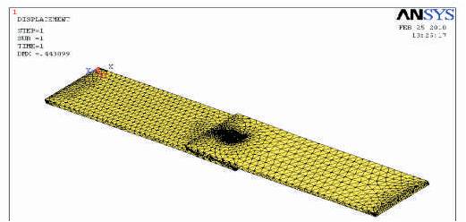
Figure 2. Meshed model of Rivet Joint
Hybrid joints have a combination of adhesive bonding and mechanical fasteners [6]. In the present case, rivet has been used as the mechanical fastener. The advantages of using a combined bonded-riveted design apply mainly in a repair situation. It is generally accepted that a bonded joint is stronger than a mechanically fastened joint and a well-designed bonded joint is stronger than a hybrid joint [4]. However, in a repair situation, limitations force the repair design to be less than an optimum joint design [3] (Figure 3).
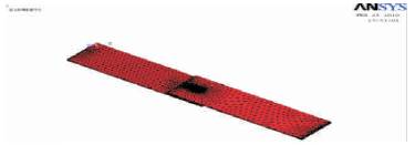
Figure 3. Meshed model of Hybrid Joint
The commercial FEA software ANSYS 11 has been used to analyze the models. The laminates (adherent) were made of carbon/epoxy composite, with a stacking sequence of (0/45/90/-45) and the adhesive used was Redux 319. Each lamina was assumed to be 0.15 mm thick. An aluminum rivet was used for mechanical fastening.
The analysis for bonded joints was performed by applying a tensile load of 5000 N at the end of the joint which was free to move in the longitudinal direction only (UY = UZ = 0). (Figure 4) The opposite end of the joint had fixed boundary condition (UX = UY = UZ = 0). The analysis for riveted and hybrid joints were performed in two steps. First, a clamping load of 6 kN was applied through the application of a pretension load at the mid-portion of the rivet. Secondly, a tensile load of 5000 N was applied to the end of the joint which was free to move in the longitudinal direction only (UY = UZ = 0). The opposite end of the joint had clamped boundary condition (UX = UY = UZ = 0).
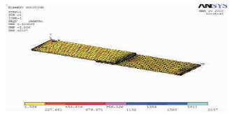
Figure 4. Analysis Result of Bonded Joint
The composite laminates of FEA model for bonded joints were developed by using Layered 46, a 3-D brick element. The adhesive layer was modeled using SOLID- 45, an 8-node brick element. The adherent and adhesive were glued together using Boolean operation. Finer mesh was used in the design.
The maximum value of stress was found to be 2037 N/mm2 and was located at the corners of the surface where the load was applied (Figure 5). The laminate had a varying stress distribution ranging from the minimum value to an order of 227.66 N/mm2. The maximum deflection was found to be 0.429028 mm.
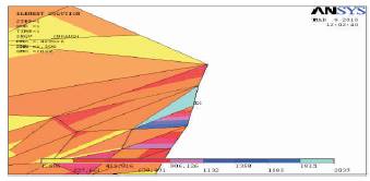
Figure 5. Max stress concentration of bonded joint
The composite laminates were designed using Layered 46, a 3-D brick element. The rivet was designed using SOLID-45, 8-node brick element. The mesh was refined adjacent to the rivet-hole and at the overlap ends. A neat fit was assumed between the rivet and laminates in all simulations. Contact was defined between the laminate and the rivet using TARGE170 element for the target and a 3-D non-linear contact element, CONTA174 for the contact, with a friction co-efficient of 0.2. Pretension section was defined at the mid portion of the rivet (Figure 6).
The minimum value of stress was found to be 1.966 N/mm2 and it was located on the laminates and the rivet head. The maximum value of the stress was found to be 16738 N/mm2 and it was located on the interface between the laminate and the rivet shank. Here the maximum deflection was found to be 0.443099 mm (Figure 7).
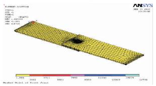
Figure 6. Element Solution of Riveted Joint
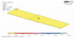
Figure 7. Nodal Solution of Riveted Joint
This model is similar to the riveted joint, except that it has a thin layer of adhesive between the laminates. The minimum value of stress was found to be 2.036 N/mm2 and was located on the laminates and the rivet head. The maximum value of stress was found to be 15063 N/mm2 and was found to be in the adhesive layer near the laminate-shank interface. Here the maximum deflection was found to be 0.447246 mm (Figures 8&9).
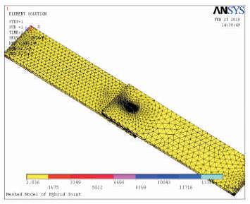
Figure 8. Element Solution of Hybrid Joint
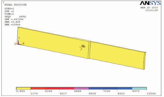
Figure 9. Nodal Solution of Hybrid Joint
In bonded joints, the stress was distributed throughout the laminate and the adhesive took up much of the load. The maximum stress is also low since the applied load alone acts on the joint, whereas in riveted joint, the maximum stress concentration was very high since pre-tension load was also applied to the joint. The rivet head and the laminate surface take up less stress compared to the interior of the laminate and the rivet shank. The case of hybrid joint is found to have a situation that is in between that of both the above joints. The rivet shank and the adhesive layer are the main areas that have maximum stress concentration. Thus, from the above observation, it was found that hybrid joint can be used in a situation where quality of bonded joint cannot be assured with certainty and where riveted joint alone is not sufficient to take up the entire load since it has characteristics in between that of bonded and riveted joints. It is mainly applicable in repair situation [1]. The study primarily considered stress distributions in the laminates and limited consideration was given to load transfer through the joint [2].
Geometric parameters in the joint were varied and the stress distributions were compared to find the efficiency of the joint as their geometrical parameters are changed. This could be realized by profiling the adherent's layer thickness quadratically or linearly to reduce or eliminate the shear stress concentration at the ends. Joints with adherent's layer thickness 0.21 mm were compared using a constant overlap length of 25.4 mm and adhesive thickness of 0.4 mm. It was found that as the number of layers decreases, the value of maximum and minimum stress concentration in the joint decreases as the stress was distributed over larger area. It was also found that as the layers number decreases, the maximum stress location shifted from the adherent where the load was applied to the adhesive layer and the then to the other adherent. Decreasing the adherent layers also increases the level of shear stress in the adhesive (Figure 10).
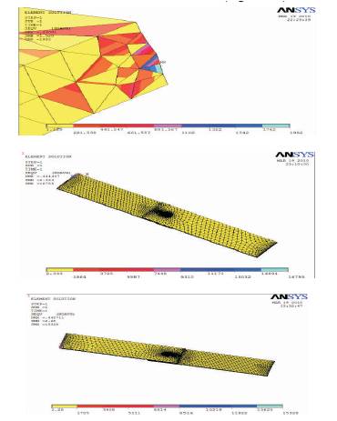
Figure 10. Max Stress Concentration of Bonded, Rivet and Hybrid Joints
In the present work, FEA for the prediction of stress distribution in bonded, riveted and hybrid joints has been carried out. 3-D models were created and analyzed using ANSYS FEA software. Von Mises stress was used to compare the results. Parametric study has been performed to reveal the effect of various geometric parameters on the stress distribution of hybrid joint. Thus from the present study, it was found that a well-designed hybrid joint is very efficient when compared to bonded or riveted joints n the case of repair situation in aircraft structures.