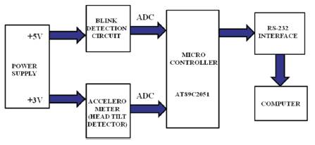
Figure 1. Block Diagram
This paper explain the basic idea to build a human machine interface which can be used to control mouse using head-tilt [8,7] and eye-blink [1]. This mouse-emulating device can be found to be most useful for physically handicapped people who can no longer control the computers using their hands [5]. Since the device relies on user's head and eye movement, it can be used even by patient who are paralyzed from shoulder downward. Simple head movement doesn't require too much energy and neither does eye blinking [3]. Therefore user won't get tired from using this device. In this device or goggle the author used 2D-accelerometer [6] for detecting the movement of the head according to which, the movement of the cursor has been done [2]. A photo sensor detects eye blinking [4]. The Infrared transceiver consists of a 935nm IR transmitter and a phototransistor is mounted on the same unit. This detects a strong increase in the reflected signal upon intentional long blink as compared to normal eye blink.
The aim is to develop a human machine interface emulating function of a mouse for disabled or paralyzed persons, since the device relies on user's head and eye movements [4], [8]. It can be used even by a patient who is paralyzed from shoulder downward. Simple head movement doesn't require too much energy, and neither does eye blinking. Therefore user won't get tired from using this device. We use accelerometer to detect the movement. When the head of the user is tilted up/down or left/right, the reading from the accelerometer is subtracted from the value of a pre-define reference point [2], [6]. The difference determines the level of head tilt. A photo sensor detects eye blinking. The Infrared transceiver consists of a 935nm IR transmitter and a phototransistor mounted on the same unit. This detects a strong increase in the reflected signal upon intentional long blink as compared to normal eye blink [1], [3]. The output of both the sensor are given to the ADC input and after on the microcontroller. After the signals are interpreted by the microcontroller, mouse instructions are sent to the computers. The processed digital information is transmitted to the PC through the serial port.
For the input mechanism, in order to detect the blink of the eye, we needed to have a photo sensor as shown in Figure1 which acts as a transceiver. Initially we selected OPB710, a reflective object sensor manufactured by optek, for the purpose. However, as the particular model was not available, we settled for OPB706 which has similar characteristics to the former, only a shorter range. The OPB706 consists of an infrared light emitting diode and an NPN silicon phototransistor mounted “side-by-side” on parallel axes in a black plastic housing as shown in Table1. On OPB706 the LED and phototransistor are molded using dark infrared transmissive plastic to reduce ambient light noise. The phototransistor responds to light from the emitter when a reflective object passes within its field of view of the device as shown in Figure 2.
Figure 1. Block Diagram
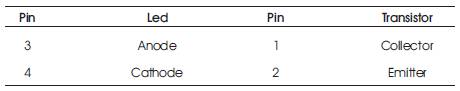
Table 1. Pin Description of OPB706
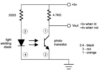
Figure 2. Circuit Diagram of Sensor.
Led Peak Wavelength = 935 nm.
Reflection distance =0.050” (1.27mm) as shown in Table 2.
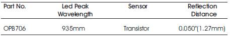
Table 2. Description of OPB706
The author decided to use an accelerometer for the determination of the degree of user's head tilt as shown in Figure 3 Accelerometer uses the force of gravity as input vector to determine orientation of object in space. When oriented parallel to earth's surface it can be used to detect the relative tilt of head. One of the most popular applications of the MMA7260Q is tilt measurement. The accelerometer uses the force of gravity as an input vector to determine orientation of an object in space. An accelerometer is most sensitive to tilt when its sensitive axis is perpendicular to the force of gravity, i.e. parallel to the earth's surface. At this orientation its sensitivity to changes in tilt is highest.
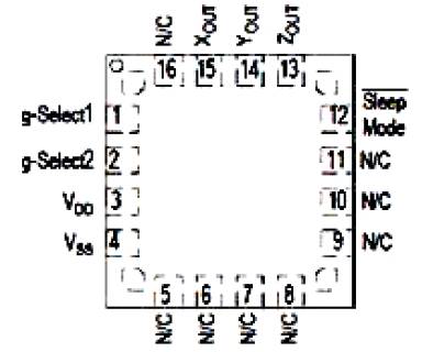
Figure 3. Pin Connection of MMA7260Q
The accelerometer consists of a g-cell as shown in Table.3 which does the work of sensing change in acceleration and hence the tilt. G-cell consists of two capacitive sensing cells, formed using 3 beams, where the middle beam is movable. Thus, these are 2 back-back capacitors as shown in Figure 4.
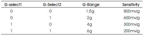
Table 3. Variable Sensitivities obtain by G-select
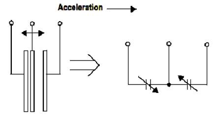
Figure 4. Simplified Transducer Model of G-Cell
1.3.1 Description
Table 3 shows the values of g-select pins and the corresponding sensitivity obtained.
1.3.2 How Does an Accelerometer Work?
Initially, the accelerometer consist of a g-cell which does the work of sensing change in accelerometer and hence the tilt. G-CELL consist of 2 capacitive sensing cells, formed using 3 beams, where in the middle beam is movable. Thus, this forms 2 back-to back capacitors.
Now, we know that capacitance is given as:
C=Ɛ0A/d
Where, A is the area of the beam.
1.0 is the dielectric constant.
2.D is the distance between the beams.
3.A is the Overlapping Area.
So, whenever there is a tilt in the either X or Y axis, the middle beam moves changing its distance with respect to the other two fixed plate. This changes the resultant capacitance of the G-cell. This change in capacitance is used to determine the output of the accelerometer. The IC also signal conditions and filters the output signal, providing a high level output voltage that is ratiometric and proportional to acceleration.
1.3.3 Filtering
The dual axis accelerometer contains onboard single-pole switched capacitor filters as shown in Figure 7. Because the filter is realized using switched capacitor technique, there is no requirement for external passive components (resistor and capacitors) to set the cut-off frequency.
1.3.4 Ratio-metricity
Ratio-metricity simple means the output offset voltage and sensitivity will scale linearly with applied supply voltage. That is as supply voltage is increased, the sensitivity and offset increased linearly, as supply voltage decreases, offset and sensitivity decreases linearly. This is the key feature when interfacing to a microcontroller or an A/D converter because it provide system level cancellation of supply induced errors in the analog to digital conversion process.
1.3.5 Accelerometer- Microcontroller Interface
Figure 5 shows the connection circuit diagram of an accelerometer:
The Vdd required for the accelerometer is the range 2.2V to 3.6V as shown in Figure 5. This is obtained from a potential divider circuit built on the accelerometer PCB having R1 as2KΩ R2 as 2KΩ thus the voltage for Vdd is obtained as: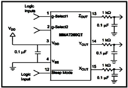
Figure 5. Circuit Diagram of Accelerometer Connection
Vdd= (R1/R1+R2) X Vin= (2K/2K+3K) X 5V= 3.33V (1)
Thus, Vdd of 3.33 V is obtained which lies within the required range of accelerometer specification.
A capacitor of 0.1 µF is connected between Vdd and Vss in order that Vdd should reach to 2.2V in less than 0.1msec.
Each of the outputs (X out and Y out) is followed by the RC filter in order to reduce the clock noise.
The output of the sensor is fed into the A/D converter for the conversion of analog signal which is the output of the sensor to digital signal which is fed to the microcontroller for further processing of data. The reason why we are using A/D as shown in Figure 8 converter is that microcontroller works on the digital signal for the further processing of data. Here we are using HD74LS90P as shown in Figure 6 to provide necessary clock pulse to the ADC.

Figure 6. Three Possible Head Tilt Movements
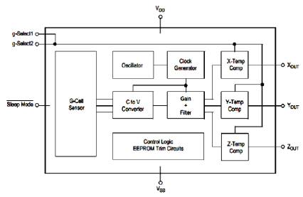
Figure 7. Functional Block Diagram of Accelerometer
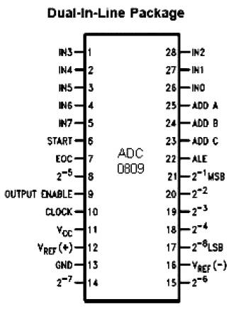
Figure 8. Pin Diagram of ADC
The output of IR transceiver and accelerometer are detected by micro-controller after getting processed through A/D convertor. The function of the micro-controller is to receive the data from A/D converter, process it and then send suitable signals to the computer's serial port. The AT89S52 is a low-power, high-performance CMOS 8-Bit microcontroller with 8k bytes of in-system programmable Flash memory. The device is manufactured using Atmel's high-density non volatile memory technology and is compatible with the industry- standard 80C51 instruction set and pin out. The on-chip Flash allows the program memory to be reprogrammed in-system or by a conventional non volatile memory programmer. By combing a versatile 8-bit CPU with in-system programmable Flash on a monolithic chip, the Atmel AT89S52 is a powerful microcontroller which provides a highly-flexible and cost-effective solution to many embedded control applications.
1.5.1 RS-232 Interface (MAX 232)
RS-232 is a serial communication cable which is needed for communication between the computer and the micro-controller as shown in Figure 9. The RS-232 communication is preferred because;
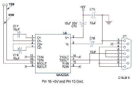
Figure 9. Pin Diagram of MAX 232
The micro-controller circuitry works with TTL logic +5V as logic 1 and 0v as logic 0. However RS-232 standard have different voltage levels. They are 3-15V for TTL logics 0 and -3 to -15 V for TTL logic 1. Hence conversion of TTL levels to these levels are required. This is done by MAX 232 IC with the help of the 1µf capacitor connected to it. The output of MAX232 is given to the RS-232 connector. It is then given to the PC through the DB-9 connector.
A fixed voltage power supply producing constant +5V as shown in Figure 10 consists of step down transformer, a bridge rectifier, filter capacitors C1 and 3 terminal regulators IC LM7805. A step down transformer is selected in such a way that it produces 9V at the input of IC. This power supply is capable of supplying +5v and load current up to 500m A. The capacitor C2 connected between output terminal and ground cancels out any inductive effect due to long distribution leads. Input capacitor C1 is used to improve transient response of the regulator IC, i.e. response of regulator to sudden changes in load. It is also helpful in reducing the noise present in the output. Dropout voltage (Vin-Vout) needs to be at least 2V under all operating conditions for proper operation of regulator.
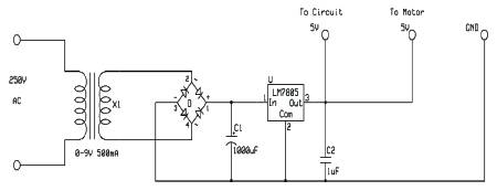
Figure 10. Circuit Diagram of Power Supply
The author are use two software's for the working of their projects. One code is placed in microcontroller for transmission of information regarding and click. Another program runs on PC to collect the data from serial port and set mouse cursor accordingly. They use the followings software's:
During the program, we first check the clicking condition that is, whether the output from IR receiver is more than 40 mV as compared to its initial value.
The IC being an extremely small SMD device was wave- soldered on a PCB as shown in Figures 15 & 16. This was done by a company called 'LongQiu semiconductors'. After soldering was complete, the authors tested the accelerometer PCB and verified that its outputs were within the range specified in its datasheets. After testing the IC by tilting it in x and y axis, it was ready to be mounted on the go.
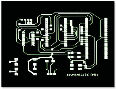
Figure 11. Printed Circuit Board of Transmitter End

Figure 12. 3-D Model of Transmitter End
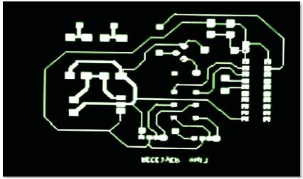
Figure 13. Printed Circuit Board of Computer End
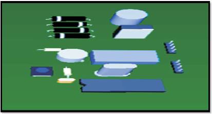
Figure 14. 3-D Model of Computer End
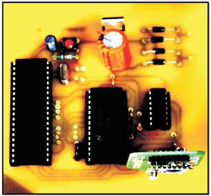
Figure 15. Glass Epoxy PCB with Soldered Component of Transmitter End

Figure 16. Glass Epoxy PCB with Soldered Component of Component End
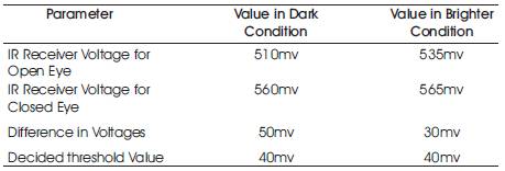
Table 4. Bread Board Testing of Blinking Detector
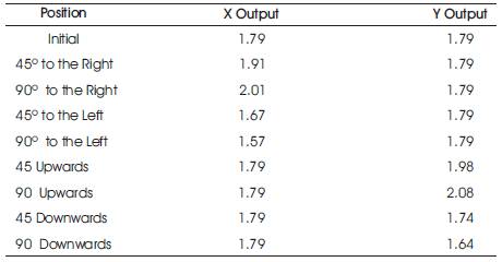
Table 5. Bread Board Testing of Accelerometer.
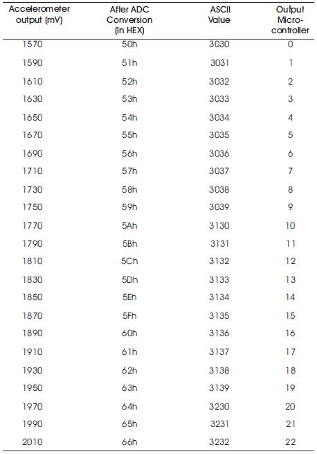
Table 6. Look-up table for X-axis
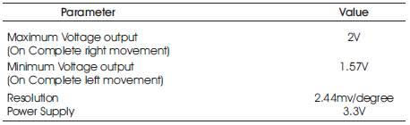
Table 7. Specification X-axis
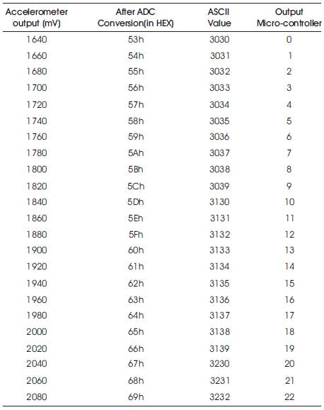
Table 8. Look-up table for Y-axis
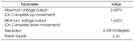
Table 9. Specification Y-axis
The authors came up with a way through which they accomplished the task of clicking and cursor movement, using eye-blink and head movement respectively. In this process, they have learned 8051 micro-controller programming.
The author have successfully implemented, tested and debugged the hardware and the software, involved in the project as shown in Figure 18.
In this project, a working prototype of the head mouse as shown in Figures 17 to 19 which perform the clicking task, and is functioning satisfactorily in all aspects. The authors use accelerometer to detect head movement. When the head of the user is tilted up/down or left/right, the reading from accelerometer is subtracted from the value of pre-defined reference point. The difference determines the level of head tilt. A photo sensor detects eye blinking as shown in Figure 18. The infrared transceiver consists of a 935nm IR transmitter and a phototransistor mounted on the same unit. This detects a strong increase in the reflected signal upon intentional long blink as compared to normal eye blink. The output of both the sensor are given to the ADC input and then after on the microcontroller. After the signal is interpreted by the microcontroller, mouse instruction is send to the computer as shown in Figure 17 .The processed digital information is transmitted to the PC through the serial port.
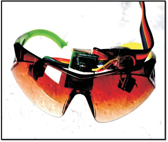
Figure 17. Goggle with Blinking Detector Sensor and Head Tilt Sensor
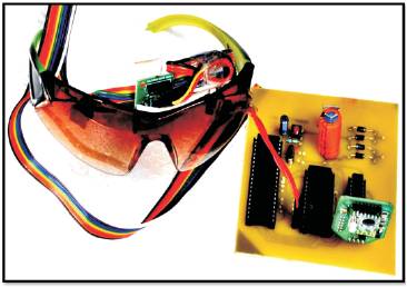
Figure18. Complete Goggle with Transmitter End
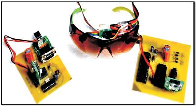
Figure19. Complete Goggle Mouse