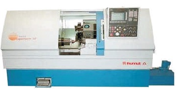
Figure 1. Upgraded CNC Machine
This paper deals with the upgradation of CNC machine and its flexibility for modern technologies. In this paper, designing of control panel and its implementation is discussed. Different components are mounted in control panel to protect the system in case of power failure and protect motors against phase down. Almost all the industries use PLCs now-a-days because it is highly compatible, reduces wiring, and makes the design more compact and reliable. This is as up-gradation of CNC machine. Generally, PLCs are programmed in “ladder logic”, which strongly resembles a schematic diagram of relay logic. Different ladder logics are developed for performing different operations. This article can be extended further by emerging it with IIoT, i.e. Industrial Internet of Things, where we can monitor CNC machines from remote place.
CNC machine is an application of PLC automation. This includes, Turret Punch Press Machine, Gun Drilling Machine, CNC Turning Machine, Grinding Machine, CNC Turret Punch Press Machine, Milling Machine, Drilling Fine Boring Machine, and Special Purpose machines. Today, they are widely used in manufacturing in combination with software programs to efficiently and consistently create different products for large companies or even single consumers.
In CNC machine, different hydraulic actions like grinding, clamp/de-clamp, etc., are performed and controlled with the help of control panel. Its hardware includes, wiring of the control panel and machine side elements like sensors, actuators, motors, and contactors.
As the clients requirement changes day by day, instead of changing the whole CNC machine, only required changes can be done in existing machine by making changes in some hardware and software part of the machine. This is the up-gradation of CNC machine (Ansar et al., 2016). Figure 1 shows the upgraded CNC Machine.
Figure 1. Upgraded CNC Machine
Before the designing of CNC machine, a manuscript is made to have an idea about the part program. It includes overall procedure, steps involved in designing, and operating the machine. Figure 2 shows the block diagram of CNC Machine.
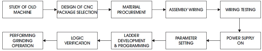
Figure 2. Block Diagram
Initially, the authors studied the traditional machine. Design of CNC and package selection is done according to the client requirement. After the assembly of components and wiring, its testing is done. Then, parameters are set before uploading the ladder. After loading the software it is verified for performing different operations (Pabla & Adithan, 2007).
Before performing upgradation, study of old CNC machine is done, which verify its operational parameters, such as modes of operation, and type of operation to be performed.
So that, we will get to know its flaws and it will be helpful in the machine development.
According to client requirements, package selection is done. For that, different packages are compared and suitable one is selected. This include selection of various components which are required for a CNC machine. The components are cable selection, motor selection, transformer selection, CNC controller selection, etc.
It ensures quality of goods in affordable price. Along with the quality of service, we need to consider location also for transportation purpose (Dhatrak & Gond, 2016).
Once the material is received, connections are done. It includes assembly of those components and wiring. Wiring is required to distribute the various voltages at different points in control panel. Three different colors for wiring are used for simplicity. These colors help to identify input signal wires, output signal wires, and wires carrying high current.
When overall connections are completed, testing is done. So that, there will not be any short circuit problem. Each wire has been checked and verified whether it provides required voltage or not. If it does not provide then the fault in the wiring is corrected.
When control panel designing and other connections are over, we can start the machine by providing power supply.
Required parameters are set before loading ladder diagram. Errors appear before loading ladder needs to be eliminated first. Parameter setting also includes setting of various motor drives such as servo drive depends on requirement.
To perform different actions on CNC ladder is needed.
An algorithm was developed for performing different actions. Then accordingly, ladder programming is done.
After loading ladder with the help of pendrive or flash cards, logic verification is done. So that, we will know if there is any error in ladder diagram or not. The logic is verified by testing the performance of CNC machine. For logic verification, job trials are taken for different operation.
The authors have developed ladder for grinding operation. Once ladder is loaded and verified for logic, actual operation takes place.
Figure 3 shows the flow chart for operation.
The operator gives an input through the operating panel. If any servo movement has to take place, respective command is given to the device. Then, accordingly signal is sent to the PLC through ladder diagram. PLC will check for the signal. If signal is correct, then it will perform the servo movement. Otherwise it will again check the signal.
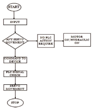
Figure 3. Flowchart
The CNC machine may have the following elements:
Ladder diagram is used to perform different operations. For each step in operation, separate ladder is designed. Ladder consist of rungs. Stepwise execution of these rungs lead to successful operation.
Different types of input media are used to store information and provide input to various control units.
In olden days, following media were used:
Punched cards and punched tapes are useful in storing data in the form of series of punched holes along their length.
Punched tapes may be made of paper, a plastic material known as Aluminium foils.
Magnetic tapes are made of plastic material and are coated with Gamma ferric oxide layer.
The advantages of magnetic tapes as input media are (i) large storage (ii) data can be erased and reused. But, now-a- days, memory cards and pen-drives are used which are easily portable.
These are small in size and can store large data.
It consist of electronic circuitry to process the program fed by means of input media and convert them into mechanical actions of the machine tool (Wadhawe & Kurtadikar, 2014).
Generally, the MCU may be of three types
Control unit is assembled inside the machine itself.
This MCU is a separate unit. It can be swung around the machine depending upon the position of the operator.
It is designed as a separate unit and placed at a distance from the machine.
Driving devices consist of different types of motors and gear trains. They convert instructions from the MCU into accurate mechanical displacements of the machine tool slides. The motors may be electrical, hydraulic, or pneumatic. Servomotor and, stepper motor are different types of motors used as drives in CNC machines.
This unit acts as a HMI and consists of different dials, switches, and a display for monitoring different actions.
The operator uses the manual control unit to:
Action of converting job to the end product is done by machine tools. Different components or devices included are spindle, motors, chuck, cutting tools, etc.
Operating pendant consists of different modes. For these modes, ladder subprogram is developed.
It is one the measure elements in CNC machine as it works as HMI (Human Machine Interface). The switches on operating pendant are shown in Figure 4.
Different modes in operating pendent are as follows:
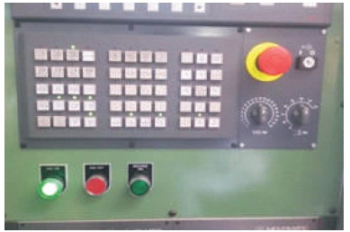
Figure 4. Switches on Operating Pendant
X1= Shift by 1 mm X 10 = Shift by 10 mm X100
= Shift by 100 mm
Due to emerging concepts like globalization and liberalization today customers change their demands frequently. Hence, market life of the product reduces bringing loss to the industry. To avoid this, upgradation is done. The senescent machine tools are restored to an accuracy level, improving availability, enhancing productivity and capability.
The upgradation is more helpful to make system economical and digitized as we do not need to make much changes in hardware. Table 1 gives the comparison between the parameters of old machine and new machine.
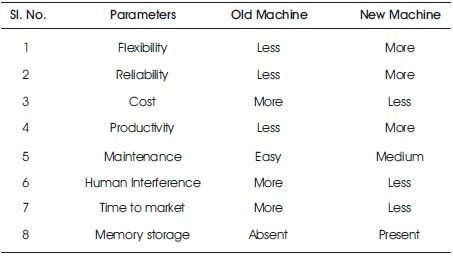
Table 1. Comparison
Components from Old CNC machine shown in Figure 5 like control panel are replaced in order to meet new system requirements. This process is also referred as dismantlement (Rajput & Sarathe, 2016).
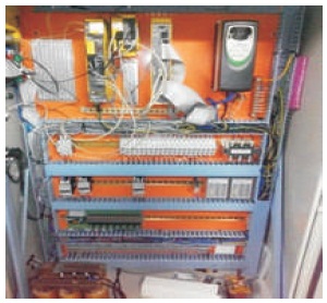
Figure 5. Old CNC Machine
Figure 6 shows control panel after dismantlement process.
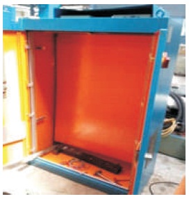
Figure 6. Control Panel Dismantlement Process
Figure 7 shows an Up - graded machine for new operations.
The new system components are fixed into the machine as per the requirement (Hindalekar & Patil, 2015).
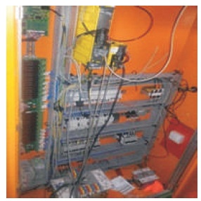
Figure 7. Up-graded Machine for New Operations
The advantages of the CNC machines are as follows.
CNC machines are mostly used in automation industries for different applications:
Technology is changing drastically day-by-day and therefore accordingly, customer demands are also changing. Without investing much cost to fulfil these demands, changes are done in existing CNC machine, i.e. upgradation. CNC machine upgradation is done by control panel designing and ladder development, making it more digitized. Flexibility has been increased hence, we can make required modifications easily by developing the software.