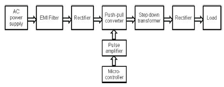
Figure 1(a). Basic Block Diagram of Proposed Topology
This paper presents the experimental verification of ZVS push-pull converter. The emphasis of this topology is to reduce the electromagnetic interference, conduction losses, and complexity of the circuit. EMI caused by power converters can disturb the normal operation of the converter and other adjacent systems. The main aim of the research work is reduction of EMI in switching power converters. Lessening techniques have been explored to reduce EMI noise effectively. The push-pull converter is used as DC-DC converter suitable for low and medium power application. High efficiency, less switching loss and high power density are the incentives of this application. The switching frequency is increased to achieve high power density which will minimize the complexity of the circuit as size of the components reduced. Thus switching loss has to be minimized to achieve high frequency operation; this can be achieved by ZVS resonant techniques. This reduces switching losses as well as EMI. The push pull DC to DC converter with EMI filter is constructed and tested. The experimental results are compared with simulation results.
Increased demand of power electronic converter for various applications such as Motor Drives, Industrial equipment, Electric Vehicles, Household appliances, Traction, Air craft's, switched power supplies etc. High power density is an everlasting topic on power electronics. The effective way to improve power density is high switching frequency. In order to boost the switching frequency, the switching loss should be reduced at first. The fast switching power semiconductor devices, such as MOSFET or IGBT are preferred as they have reduced switching losses, small in size, lower in cost and as higher efficiency.
However, fast switching speed of converter topology will leads to emission of EMI. The EMI generated by switching power converters interferes with the normal operation of other sensitive equipment and may cause operating faults. EMI is a serious problem in power electronics because of their fast switching characteristics [5], which can cause disturbances in nearby electronic equipment as well as in wireless communication.
The study on soft-switching push-pull converter has become more and more essential. The soft switching technique i.e. ZVS /ZCS have been used to reduce EMI [2]. Theoretical and experimental results of power converter frequency modulation are given by Santoralia [3] .The Characterization of EMI is given in literature [1], effect of switching frequency on EMI [4] and evaluation of EMI [5-7]. A new gating technique for soft switched DC/DC converter [8].The active common mode EMI filter for PWM inverter is proposed by Son [9] and improvement in efficiency, power density and EMI was presented [10-18]. The review of push-pull converter is given in [19].
The basic block diagram of push-pull converter is shown in Figure 1a. In this DC input fed to push-pull inverter is converter to high frequency AC. The AC output voltage is seen with noise present in it. This is fed to the EMI filter to get the sinusoidal output . It is seen that the noise is reduced.
Figure 1(a). Basic Block Diagram of Proposed Topology
This AC output is stepped down by using step down transformer; the AC voltage is rectified by using a rectifier. The rectified voltage feeds the load.
The above literature does not deal with modeling and simulation of push-pull converter with EMI reduction circuit.
This paper, will address the noise attenuation by using suitable EMI filter. Thus switching losses will be reduced greatly, its efficiency is improved with high power density. The circuit model for ZVS push-pull DC/DC resonant converter fed motor drive is developed with EMI filter. Simulation results justify the performance.
The paper is organized as follows. In section II the basics of push-pull converter and EMI filter are presented. In section III the circuit description and operating principle of proposed topology is presented. In section IV, simulation results of push-pull converter without and with EMI filter are presented. In section V the experimental results are presented. Finally, section VI gives the conclusion of the proposed work.
The incentive of reduced conduction loss eminence the use of push pull converter as DC/DC converter in low and medium power UPS systems than that of half-bridge or full bridge converters. Figure 1b gives the basic circuit diagram of push-pull converter and Figure 1c represent the typical waveforms of push-pull converter.
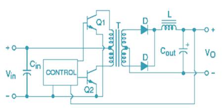
Figure 1(b). Basic Push-Pull Circuit Diagram
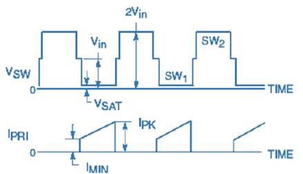
Figure 1(c). Typical Waveforms of Push-Pull Converter
A push-pull converter is a DC to DC converter; the DC power supply is changed by using a transformer. The transformation ratio is arbitrary but fixed; hence in most of the circuit implementation the duty cycle of the switches can be varied to vary the range of voltage ratios. The advantages of using push-pull converter are simplicity and ability to vary to high power application, which leads to increased use in industrial DC power application.
The switch Q1 is switched on, hence the current flows through the upper half of transformer primary winding T1 . The magnetic field of T1 gets expanded and links with the secondary winding induces voltage on secondary of transformer . The polarity is assigned for the diodes i.e. D2 is forward biased and D1 is reverse biased. As D2 is forward biased it conducts and charges the output capacitor C 2 through L1 . The LC filter is formed by L1 and C2 .When Q turned off, the magnetic field in T1 gets collapsed and after a period of dead time based on duty cycle, Q 2 conducts. Hence current flows through the lower half of transformer primary winding T1 . Similarly the magnetic field gets expanded, but the direction of magnetic flux is reversed and it is in opposite direction to the flux produced when Q1 is turned on. The expanding magnetic field induces voltage across T1 secondary, now the polarity of D1 is in such a way that it is forward biased and D2 is reverse biased. As D1 conducts it charges the output capacitor C2 through L1 After a period of dead time Q1 conducts and the cycle gets repeated.
The voltage across the inductor L is
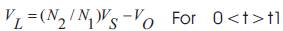
At the end of interval t1, there is no induced voltage in the secondary winding. Hence the switch S1 is turned off, in this interval diodes DA and DB conducts and forces the voltage on the inductor L to be –Vo. Because of this condition that the average voltage on the inductor L must be zero in each half switching period, we obtain
The Figure 2a shows the Push-Pull inverter circuit with EMI filter. The noise in the input AC is filtered and it is applied to the Push-Pull inverter.
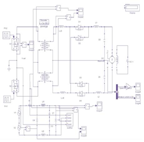
Figure 2 (a). Circuit Diagram of Push-Pull Converter with EMI Filter
The simulation of push-pull DC/DC Converter fed DC drive system is done using MATLAB and results are presented here. The Specifications of elements used for simulation area s follows L1 = L2= 90 μH , Ls3= Ls4 = 90μH , C1 =C2=2200μF. The parameters related to EMI filter component are Lf1 = Lf2 = 20mH, C1=C2 = 5ns, C3 =120μF, C4= 0.1μF and R=0.1Ω. The Driving pulses for M1 and M are shown in Figure 2b. Driving pulses given to M1 and M2 are shifted by 180. AC input voltage applied is shown in Figure 2c. Output of EMI filter is shown in Figure 2d. Transformer primary voltage is shown in Figure 2e. The secondary voltage is shown in Figure 2f. Speed of Motor is shown in Figure 2g. Armature current is shown in Figure 2h.

Figure 2 (b). Switching Pulser for MOSFETS M1 & M2
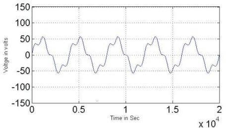
Figure 2 ( c). AC Input Voltage
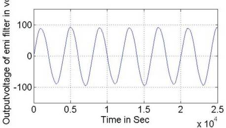
Figure 2 (d). Output Voltage of EMI Filter
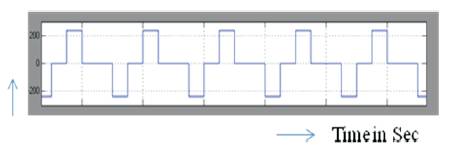
Figure 2 (e). Transformer primary voltage
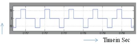
Figure 2 (f). Transformer secondary voltage
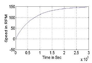
Figure 2(g). Speed of Motor
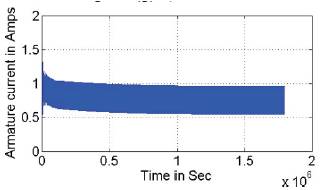
Figure 2(h). Armature Current
The hardware of push-pull DC/DC Converter is tested successfully and results are presented here.
The Constructed push-pull converter circuit is shown in Figure 3a. The AC input voltage with EMI is shown in Figure 3b. The EMI filter output is shown in Figure 3c Driving pulses for M1 and M2 are shown in Figures 3d & e. Driving pulses given to M1 and M2 are shifted by 180. Voltage across the primary is shown in Figure 3f.Voltage across the secondary is shown in Figure 3g. The 12V DC Output voltage of converter system is shown in Figure 3h. DC output voltage measured using multimeter is shown in Figure 3i.
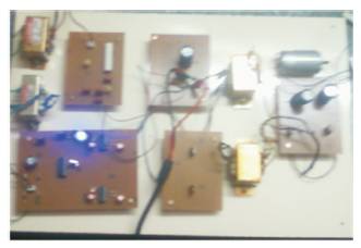
Figure 3(a). Prototype Model
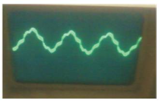
Figure 3(b). AC Input Voltage with EMI
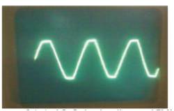
Figure 3 ( c). AC Output voltage of EMI Filter

Figure 3(d). Switching Pulse of MI

Figure 3(e). Switching Pulse of M2
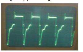
Figure 3(f). Transformer Primary Voltage
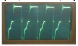
Figure 3(g). Transformer Secondary Voltage

Figure 3(h). DC Output Voltage (12v)
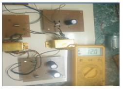
Figure 3(i). DC Output Voltage
The push-pull converter system with EMI filter is constructed successfully and their results are presented in this paper. The experimental results obtained are the same as the simulated results. The converter presents a range of avenues for new research. Push-Pull DC/DC Converter can be used to increase switching speed, reduce switching losses, reduce hardware and EMI. The decrease in switching loss improves efficiency. The contribution of this work is the control of PMDC motor using push-pull converter. The experimental result of push pull DC to DC converter coincides with the simulation results. The contribution of their work is the design and implementation of PIC based ZVS DC to DC converter.