Abstract
Due to the peak energy and power density, the battery is a leading energy source for electric vehicles. Among various battery chemistries, Li-ion batteries have emerged as serious competitors in the field of electric vehicles. The battery cells are connected in series or parallel to increase voltage and current in a battery pack for electric vehicle applications. The heart of a battery-operated electric vehicle is the battery control system. The series-connected cells in a battery pack must preserve each cell's original potential under ideal charging and discharging conditions. If the potential of connected cells is not balanced, the charging and discharging of cells in the pack will be affected, bringing up the issue of cells that are out of balance due to inherent and extrinsic factors. Using active and passive cell balancing techniques can solve this issue. The right cell balancing technique can shorten the battery pack's equalization time and enhance its ageing. This paper explains the parameters of a battery, the function of the BMS, and different cell balancing techniques for use in electric vehicle applications
Keywords:
- Electrical Vehicles
- Battery Management System
- SOC Estimation
- Passive Cell Balancing
- Energy
Introduction
Electric vehicles use lithium-ion cells as energy storage devices due to their high power density, thermal and chemical stability, eco-friendliness, and long lifespan. However, these cells have a limited capacity and voltage range, which requires the use of battery packs made up of parallel and series cell arrangements. Assembling the battery pack may put some cells under excessive stress due to differences in capacity, necessitating the installation of a Battery Management System (BMS) to monitor voltage, temperature, and State of Charge (SOC) to prevent over-stressing and estimate the battery's remaining energy (Jeyashree & Kumar, 2021). The BMS also ensures the balance of the pack, preventing overstressing of cells with reduced capacity and limiting user access to the full pack capacity. Failure to maintain the voltage range can result in irreversible damage or even a fire, emphasizing the importance of the BMS in EVs. Therefore, it is necessary to stabilize the battery pack and ensure that each cell has the same SOC to maintain the well-being of the cells and consume the full amount of useful energy. Both passive and active strategies can be used to accomplish this. The passive cell balancing method is used in this paper, where the BMS can balance each cell in the battery pack.
1. Literature Review
Jeyashree and Kumar (2021) says battery cells are typically connected in series or parallel to create a battery pack that can provide higher voltage and current for electric vehicle applications. The battery management system acts as the heart of the battery operated electric vehicle, and modeling the battery pack system is a necessary step in developing any proposed battery management system. The cells connected in series within the battery pack should ideally maintain the same potential under both charging and discharging conditions.
Wang et al. (2009) depicts testing a LiFePO4 battery and evaluating its capacity, DCR, and OCV under different ambient temperatures. The voltage hysteresis test was conducted using simulated current profiles from HEV models, and the results are discussed along with recommendations for the application of this battery in electric vehicles.
Maleki and Howard (2006) mentions the effects of over discharge on the cycle-life and thermal stability of a commercially available Li-ion cell rated at 780 mAh. Cells were over-discharged and kept at 2.0, 1.5, 1.0, 0.5 or 0.0 V for 72 hours, then cycled five times (discharged to 3.0 V at 0.4 A and charged to 4.2 V at 0.8 A), with the process repeated five times. Cells over-discharged between 2.0 and 0.5 V experienced irreversible capacity losses of 2- 16%.
Bentley (1997) investigates charge algorithms for Li-ion batteries for stopping the charging current once a maximum voltage threshold is reached. Each battery in a Li-ion pack must be individually monitored for this condition, so charging of the entire pack ceases as soon as one cell reaches this voltage limit. Cell balancing algorithms seek to remove charge from the overcharged cell to equalize the voltage and enable further charging of the pack. This paper considers the technical merits of this approach and the issues associated with its implementation.
Hariprasad et al. (2020) analyzes how a battery management system can keep the battery safe, reliable, and increase its lifespan without entering a damaging state which involves monitoring voltage, current, ambient temperature, and other factors. For monitoring purposes, various analog/digital sensors with microcontrollers are used. This paper addresses the state of charge, state of health, and state of life, as well as the maximum capacity of a battery.
2. Methodology
The greatest threats to the global automotive industry are those related to energy and the environment. The global development of new energy sources has accelerated in order to solve these issues. The methodology for implementing passive balancing in a Batter y Management System (BMS) for electric vehicles involves several key components. The BMS must be designed to accurately monitor the State of Charge (SOC) of each individual battery cell in the pack. This is typically achieved using voltage and temperature sensors, as well as advanced algorithms for SOC estimation. The BMS must be designed to implement passive cell balancing, which involves diverting excess charge from fully charged cells to those that are undercharged. This can be achieved using a passive balancing circuit, which is typically composed of resistors or diodes that allows transfer of charge between cells. The effectiveness of the passive balancing system can be evaluated by monitoring the SOC of each cell over time and comparing the results to a benchmark value. The system should be designed to minimize energy losses due to the balancing process and to ensure that the battery pack operates within a safe temperature and voltage limits.
2.1 Battery Management System
Because the power unit used in vehicles should not be exposed to excessive charging or discharging, the Battery Management System (BMS) is an essential part of electric vehicles. If such an event occurs, the battery may become damaged, the temperature may rise, the battery's lifespan may be reduced, and occasionally, the people using the device may also be affected (Wang et al., 2009). By fully utilizing the battery charge stored in the vehicle, it's life can be increased (Ranawat & Prasad, 2018). The need for a BMS arises from reasons such as the requirement to preserve the solidity and safety of the battery, to observe and control the SOC of each cell, and to manage the cell balance by monitoring the charge capacity of each cell.
The block diagram of a BMS, which is utilized to calculate SOC, cell balance, etc., is shown in Figure 1 (Hariprasad et al., 2020).
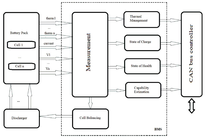
Figure 1. Cognitive and Attitude Themes Model
When designing a BMS, certain factors must be taken into consideration, such as the calculation of SOC, charging control, discharging control, and cell balancing.
2.1.1 Calculation of SOC
SOC is used as a measurement of the battery's charge level in the vehicle, particularly when the power unit is almost full. At this stage, a constant voltage is supplied to the battery at a very low current. However, estimating the battery capacity is not as straightforward as it may seem, as one needs to continuously monitor the battery's potential and charge/discharge current (Maleki & Howard, 2006). There are numerous algorithms that can be employed to determine the SOC of the battery pack once the potential and current have been measured (Ravi & Surendra, 2021).
2.1.2 Charging Control
In addition to monitoring discharging, the BMS should also keep an eye on the charging process. Improper charging can cause damage to batteries and reduce their lifespan. For lithium batteries, a two-stage charger is typically used. During the first stage, known as Constant Current (CC), the charger delivers a steady current to the battery. During the second stage, known as Steady Voltage (SV), the charger provides a steady voltage to the battery at a very low current when the battery is almost full (Ravi & Surendra, 2021).
2.1.3 Control of Discharging
The BMS is responsible for keeping the lithium-ion cells within a safe operating range. For instance, a typical lithium cell may have a low voltage rating of about 3 volts. Therefore, the BMS must ensure that the cells in the pack are not discharged below 3 volts (Ravi & Surendra, 2021).
2.1.4 Balancing of a Cell
When a battery is fully charged, "cell balancing" is necessary to balance the voltages and SOC in the cells.The most popular battery chargers can detect when a battery is fully charged by checking whether the voltage has reached the voltage regulation point throughout the cell chain (Bentley, 1997). During passive balancing, energy is extracted from the cell with the highest charge and dissipated as heat, usually through resistors (Ravi & Surendra, 2021).
2.2 State of Charge (SOC) Estimation
The state of charge refers to the percentage of the battery's nominal capacity that is readily accessible. The battery management system can assess the battery's charge status, monitor the charge and discharge, and determine whether it is operating within the safe operating range, thereby prolonging the battery's lifetime (Chang, 2013). The state of charge may not be easily estimated.
By using the mathematical equation,

where, I is the electron flow through the cell current and Cn is the battery's largest storage volume (Hariprasad et al., 2020). The graph plotted for SOC against the voltage in state of charge during charging and discharging is shown in Figure 2.
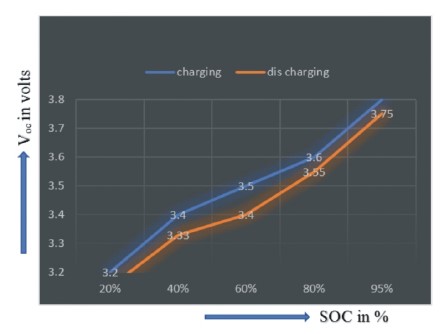
Figure 2. State of Charge During Charging and Discharging.
Various methods are used for the estimation of the state of charge (SOC), such as the Kalman filter method, the Coulomb Counting method, the Fuzzy Logic method, and the Open Circuit Voltage method (Hariprasad et al., 2020).
2.2.1 Kalman Filter Method
State of charge (SOC) estimation is a critical component of battery management systems for electric vehicles. It enables the BMS to accurately monitor the charge level of each cell in the pack. One of the commonly used methods for SOC estimation is the Kalman filter method, which is a mathematical algorithm that can be used to estimate the state of a system based on noisy measurements. The Kalman filter works by using a model of the system dynamics to predict the expected state of the system and then combining this prediction with measurements of the system to update the state estimate. Figure 3 shows the state of charge estimation using the Kalman filter method.
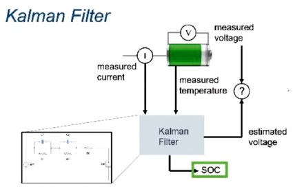
Figure 3. State of Charge Estimation Using Kalman Filter Method.
In the case of SOC estimation, the model might include information about the battery chemistry, charging and discharging rates, and other factors that affect the battery's behavior. The Kalman filter can also be used to estimate other parameters of the battery system, such as the internal resistance and capacity of each cell. This information can be used to optimize the operation of the battery pack and to detect any abnormal behavior that might indicate a fault or degradation of the cells. Using the Kalman filter for SOC estimation in a BMS for electric vehicles can provide a robust and accurate method for monitoring the charge level of each cell. This is essential for implementing passive balancing and other energy management strategies. However, the implementation of the Kalman filter requires careful attention to the design of the system model and the measurement sensors, as well as tuning of the filter parameters to ensure optimal performance.
2.2.2 Coulomb Counting Method
This method estimates the SOC of the battery pack by integrating the current flow into and out of the battery over time. The Coulomb counting method works by measuring the current flow into and out of the battery and integrating this measurement over time to estimate the total charge that has been delivered to or extracted from the battery. This estimated charge can then be used to calculate the SOC of the battery based on the total capacity of the battery pack. The flowchart for the estimation of SOC using the Coulomb Counting Method is shown in Figure 4.
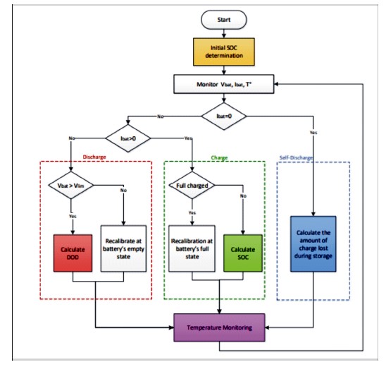
Figure 4. Flowchart for the Estimation of SOC using Coulomb Counting Method
However, the Coulomb counting method can be affected by a number of factors that can introduce errors into the SOC estimate. These factors include changes in battery temperature, variations in battery chemistry, and losses due to parasitic loads or other inefficiencies in the system. To minimize these errors, the Coulomb counting method can be combined with other SOC estimation techniques such as the Kalman filter or the Open Circuit Voltage method, which can provide more accurate estimates of the battery state. Additionally, the BMS can be designed to monitor other parameters of the battery system, such as the temperature and voltage of each individual cell, to provide a more complete picture of the battery state. The Coulomb counting method can provide a simple and effective means of estimating the SOC of a battery pack for electric vehicles, but it should be used in conjunction with other techniques to ensure optimal performance and accuracy.
2.2.3 Fuzzy Logic Method
The linguistic variables for each input variable, such as "high," "medium," and "low," are defined to represent the different levels of each variable. Linguistic variables are also defined for the output variable, SOC, which can take on values from 0 to 100%. The fuzzy logic system uses a set of rules to determine the SOC of each battery cell based on the input variables. Figure 5 shows the fuzzy logic method for the estimation of SOC.
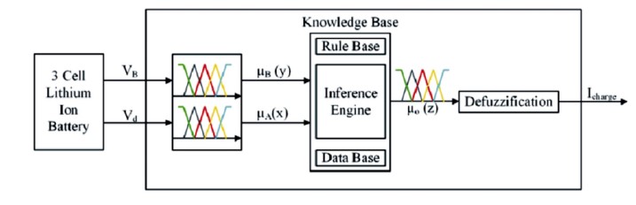
Figure 5. Fuzzy Logic Method for Estimation of SOC
These rules are defined by the authors based on their experience and knowledge of battery behavior. The battery pack consists of six lithium-ion battery cells. The results showed that the fuzzy logic-based method provided accurate SOC estimates for each cell in the battery pack, with an average error of less than 3%. The fuzzy logic-based SOC estimation method proposed in the paper provides a promising approach to estimating the SOC of battery cells in electric vehicle battery management systems.
2.2.4 Open Circuit Voltage Method
The Open Circuit Voltage (OCV) method estimates the SOC of a battery cell by measuring its open circuit voltage, which is the voltage across the cell when it is not connected to any load. The authors used a polynomial function to relate the OCV of the battery cell to its SOC. The battery cell is first disconnected from the load and allowed to rest for a period of time to allow the voltage to stabilize. The OCV is then measured, and the polynomial function is used to estimate the SOC of the cell. The Open Circuit Voltage method is shown in Figure 6.
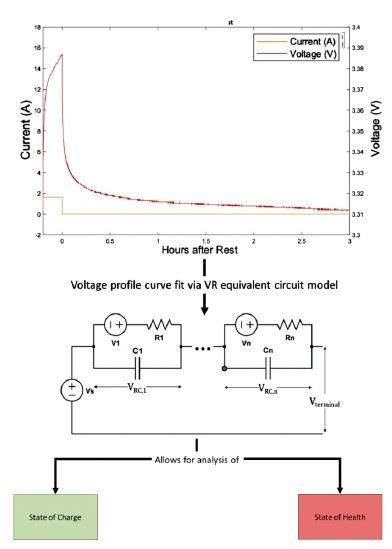
Figure 6. Open Circuit Voltage Method.
The OCV method was tested on a battery pack consisting of six lithium-ion battery cells, and the results showed that it provided accurate SOC estimates for each cell in the pack, with an average error of less than 2%. This method has the advantage of being simple and low-cost, as it does not require the use of sensors to measure current, temperature, or other variables. However, it may not be as accurate as complex methods, such as the fuzzy logic based method, particularly under dynamic operating conditions where the battery is subjected to varying loads and temperatures.
2.3 Passive Cell Balancing
The process of bringing all tension load cells and load states to the same level when the battery is fully charged is known as cell equilibrium. Typically, each battery's charger only determines when all the cells have been fully charged up to its voltage regulation point. With the aid of resistors, energy is removed from the cell with the highest charge and released as heat during passive balancing. In active balancing, the high-charged battery cell is discharged, and it charges the low-charged battery cell in the pack using capacitors and inductors.
Active cell balancing is relatively difficult compared to passive balancing (Ravi & Surendra, 2021), as it redistributes charge between the cells, which increases the run time and reduces charge time. In passive balancing, the fully-charged battery cells are simply discharged to the under-charged cell. The time taken for run time is low, and charge time is more, and heat will be dissipated through a resistor (Thiruvonasundari & Deepa, 2021; Valda & Kosturik, 2015). Figure 7 shows the concept of cell balancing and how each battery cell's SOC is balanced.
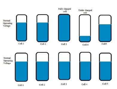
Figure 7. Concept of Cell Balance.
To balance the cells inside the battery, passive cell balancing involves evacuating the load (Cao et al., 2008) as shown in Figure 8.
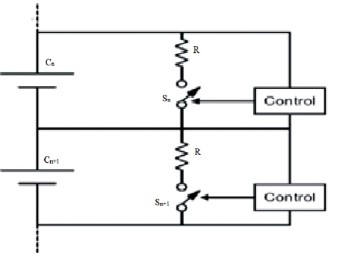
Figure 8. Passive Balancing Circuit.
In C , C represents the cell that needs to be balanced, n n denotes the number of cells in the battery pack, and R denotes the parallel resistance connected across each cell. In S , S represents the Shunting resistors and n n represents the number of resistors. When the SOC of cell 1 is higher than that of cell 2, the fully-charged cell is discharged. In the passive balancing strategy, the highlycharged cells are discharged through shunting resistors to achieve equalization (Nath & Rajpathak, 2022).
2.4 Simulation Circuit and Output Results
Figure 9 shows a battery pack consisting of 13 cells, each with a voltage rating of 3.7V and 4Ah, and having SOCs of 70%, 80%, 60%, 65%, 70%, 75%, 65%, 75%, 65%, 70%, 80%, 75%, and 65%, connected in series. When the simulation circuit runs, the SOC of cell 1 is compared with that of cell 2. If cell 1's SOC is higher than that of cell 2, a switch connected in series with cell 1 is activated until its SOC reaches that of cell 2. Similar comparisons are made between cell 1's SOC and those of the other cells in the battery pack. If cell 1's SOC is higher than that of any other cell in the battery pack, it discharges to the cell with the lowest SOC. Similarly, all the remaining cells are individually compared with other cells, and at the end, the SOC of each cell is balanced (Nath & Rajpathak, 2022).
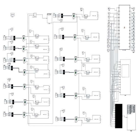
Figure 9. MATLAB Simulation of Passive Balancing Circuit of 13 Cells Connected In Series
The simplest method to comprehend the idea of cell balance is through passive cell balancing. Compared to active cell balancing, the time required for passive cell balancing is significantly shorter. However, one of the disadvantages of using passive cell balancing techniques is the loss of charge through heat dissipation.
Figure 9 illustrates the passive cell balancing circuit simulated using MATLAB, and Figure 10 displays the results obtained during the simulation, demonstrating how the SOC of each cell is balanced.
The simulation circuit shown in Figure 9 successfully balances the SOC of each cell, as shown in Figure 10. Each cell's SOC is properly balanced within 15 to 20 seconds, indicating that passive balancing works fast for cell balancing.
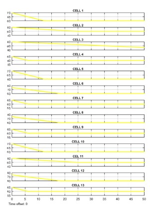
Figure 10. SOC Balancing of Each Cell.
Conclusion
This model was constructed to regulate and control the performance of these characteristics, which are crucial for maintaining the health of the battery pack. To guarantee battery safety and dependability, the BMS needs to be kept in good working order. Passive cell balancing for 13 series-connected cells is considered the simplest and easiest method to understand balancing techniques. The passive balancing technique has its benefits, such as being a low-cost solution, but it also has its drawbacks. The runtime of the balancing is low, and there is a problem with charging dissipation in the resistance, which leads to heat dissipation and increases the thermal temperature of the circuit. The BMS continuously monitors and protects the battery cells from faults, which is vital for battery safety. Thus it ensures that the battery pack is always operating within safe operating limits and detects any anomalies that could potentially cause harm. The BMS plays a critical role in ensuring the safe and reliable operation of battery packs and is carefully designed to suit the specific requirements of the application.