(1)
Power quality analysis is a classical problem in Electrical Engineering, since the electrical signal contains transients' disturbances, that can be caused for diverse reasons: Switching of electrical motors, capacitor banks, etc. For improving the power quality knowledge, it is necessary to analyze efficiently the different disturbances. The objective is to identify the transients in real time, to be corrected immediately. One of the most important issues in power quality problems is, how to detect and classify disturbance waveforms automatically in an efficient manner. Automatic disturbance recognition can be carried out with the help of a wavelet transform. The approach proposed in this paper is robust in detecting and localizing a wide range of power disturbances such as fast voltage fluctuations, short and long duration voltage variations, transients, noise and harmonic distortion.
Intelligent technology demands power, that is free of interruption or disturbance. The consequences of large scale power incidents are well documented. Any disturbance in the voltage, current or frequency of the power signal, that can adversely affect the customer's equipment can be termed as power quality problem. Phenomena, such as lightning, load variation and capacitor switching are some of the most frequent causes of power quality problems [1-3]. International standards define power quality as the physical characteristics of the electrical supply provided under normal operating conditions that do not disrupt or upset the customer's process [4-6].
For the single disturbance identification, some advanced mathematical tools, such as S-transform [7], wavelet transforms (WT) [8], Hilbert–Huang transform [9], and mathematical morphology [10], were adopted to extract the eigen vectors.
Power quality data are considerably important in terms of both obtaining statistical data for power systems and having a reference source for power quality improvement studies [11]. Consequently, power quality monitoring and classification have become an essential service, which many utilities perform for their customers. The monitoring and analysis tools must be able to detect, identify, and localize the disturbances on the supply lines and make proper system decisions. Event data obtained in the measurements, that are done with traditional power quality monitoring devices are first saved in the device and then transferred to a computer, when they are needed. Analyses are carried out both in the device and computer, and the disturbance type is determined. Data analysis in this way is quite cumbersome, time-consuming and difficult. Owing to these disadvantages, significant studies on designing intelligent power quality monitoring systems have been done in recent years [12-17].
Fourier analysis, which realizes a signal into constituent sinusoids of different frequencies is the most well-known of signal analysis methods. It is a mathematical technique for transforming a signal from a time-based one to a frequency-based one. For many signals, Fourier analysis is extremely useful because the signal's frequency content is of great importance. FFT assumes, that the signal characteristics does not change over time, which is untrue in case of non-stationary waveforms resulting into large errors and hence leading to unrealistic and inaccurate PQ evaluation. The Power Quality Indices (PQIs) evaluation based on the Fast Fourier Transform (FFT) involves limitations as high computational effort, time related information loss, and spectral leakage are involved, and therefore new approaches are necessary [18-20].
Wavelet transform (WT) has the capability of extracting information from the signal in both time and frequency domains simultaneously and has been applied in the detection and classification of power quality disturbances[21-24]. WT provides magnitude and phase information of the harmonics [25-26] and detects the sag/swell in the presence of noise or transient. This paper provides the simulation analysis of voltage events such as sag, swell, interruption, harmonics and detection using WT. The Wavelets family is most suitable for the detection of disturbances is Daubechies, Symlets with 8 support coefficients, and De Meyer [27].
Wavelet analysis is the new tool for monitoring power quality problems. Wavelet transformation has the ability to analyze different power quality problems simultaneously in time and frequency domain. The wavelet transform is useful in detecting and extracting features of various types of electric power quality disturbances, because it is sensitive to signal irregularities but insensitive to the regular signal behavior. Wavelet analysis deals with expansion of functions in terms of a set of basic functions, like Fourier analysis. However, wavelet analysis expands functions not in terms of trigonometric polynomials, but in terms of wavelets, which are generated in the form of translations and dilations of a fixed function called mother wavelet. Compared with Fourier transform, wavelet can obtain both time and frequency information of signal, while only frequency domain information can be obtained from Fourier transform.
Wavelet transformation (WT) has the ability to analyze different power quality problems simultaneously in both time and frequency domains. Wavelet analysis expands functions in terms of wavelets, which are generated in the form of translations and dilations of a fixed function called the mother wavelet. A mother wavelet is a function that oscillates, has finite energy and zero mean value.
Multi Resolution Analysis (MRA) was initially developed to decompose signal into various resolution levels to facilitate a very fast time-frequency analysis. A natural way of introducing wavelets is through the MRA. MRA provides a natural framework for the understanding of wavelet bases. A multi-stage filter bank is used to decompose the signal into various levels using a Low Pass (LP) filter and a High Pass(HP) filter as shown in Figure 1. The LP filter will result in approximate coefficients of the original signal and the HP filter in detailed coefficients of the signal. The advantage of MRA over FFT is that, the first method allows the analysis of phases and frequencies.
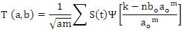
Discrete wavelet transform (DWT) is defined for a continuous time signal s(t), where discrete values of a and b are used.
Where the integers m and n control the wavelet dilation and translation respectively.
ao is a specified fixed dilation step parameter set at a value greater than 1 and bo is the location parameter which must be greater than zero.
Discrete Wavelet Packet Transform (DWPT) is a generalization of DWT. The difference is that in the WP signal decomposition, both the approximation and detailed coefficients are further decomposed at each level. This leads to a decomposition tree which is shown in Figure 1. This will lead to an array of wavelet packet coefficients with M levels, each containing N coefficients. A total of N coefficients from this M*N array can be selected to represent the signal.
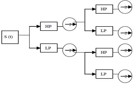
Figure 1. Depicting DWPT Filter Bank Implementation of a Signal
The main advantage of DWPT is better signal representation than decomposition using MRA. The DWT technique is not suitable for harmonic analysis because the resulting frequency bands are not uniform. In DWPT, with clever manipulation of sampling frequency, the important harmonics such as odd harmonics can be made the center frequency of the resulting frequency bands. Furthermore, DWPT gives uniform bands which are important for harmonic identification purposes. A level 2 decomposition using DWPT filter bank can be depicted as in Figure 1.
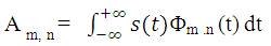
Similar to DWT, LP filter gives approximation coefficients and HP filter gives detailed coefficients. The coefficients are given by the following equations:
Let Φ be the scaling equation (or dilation equation) associated with the mother wavelet. Then, the scaling function can be convolved with the signal to produce approximation coefficients given by
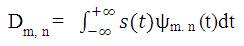
The function of mother wavelet can be convolved with the signal to produce detail coefficients given by
Often power researchers tend to neglect the choice of appropriate wavelet filter for their application. The selection of wavelet assumes more importance, if one wants to implement their algorithm in DSP and develop an instrument out of it. It is a general trend among researchers to take db10 (more appropriately higher order db coefficients) to study harmonics and db or db to study transient related phenomena. In this paper, an attempt is made to study PQ problems and to suggest a suitable wavelet filter as shown in Table 1, which can be used to study harmonics in particular. Further, symlets mother wavelet is used for analysis of power quality disturbances.
Table 1. Mother Wavelet Family
The family of symlet wavelet is short of “symmetrical wavelets” are shown in Figure 2. They are designed, so that they have the least asymmetry and maximum number of vanishing moments for a given compact support. The symlet family minimizes the effect of noise in classification of power quality disturbances. The Symlets were chosen, because they had better results in this task than any other families analyzed, Daubechies and Coiflets. Sym7 was used for analysis of harmonic signals and sym6 was used to analyze other power quality disturbances.

Figure 2. Illustration of Symlet Mother Family Wavelets
The PQ disturbance waveforms are obtained by using mathematical models of power distribution test model in MATLAB/Simulink software. Also few cases are captured in real time using Digital Storage Oscilloscope and analyzed using Wavelet Transform. The sampling frequency and fundamental frequency in all the cases are considered as 20 KHz and 50 Hz respectively. In this paper, the authors’ have applied the 6th order Symlet mother wavelet to be appropriate for detecting various disturbances and eliminating harmonics. After being decomposed into level 6, approximation 6 component has only fundamental frequency component. Mother wavelet which is over 10th order is relatively slow for computation speed compared with low order mother wavelet. Therefore, the choice of 6th order wavelet plays a significant role in detecting disturbances. WT is applied to detect the voltage disturbances such as voltage sag, swell, interruption, harmonics, notching and noise. The voltage events are shown in Figures. (3) - (9). It shows the detailed coefficients of WT at level 6 obtained with sym6 mother wavelet.
The detection and localization of this disturbance using Sym6 are shown in Figures (3) -(9). As far as the detection and the localization are concerned, the first inner decomposition level of the signal (d1) is normally adequate to detect and localize any disturbance in the signal. The wavelet transform coefficients with high values indicate the power quality disturbance events and the exact location of the disturbance. The other part of the decomposed signal of detail d1 is smooth indicating that, the signal follows some regular patterns in those periods without having any electrical noise. Detail d1 shows the exact location of the disturbance. The approximation a6 reveals the fundamental of the signal.
An interruption is defined as the complete loss of supply voltage or load current. The duration may range from 0.2 cycles to 2 seconds. The MRA of voltage interruption is shown in Figure 3. The coefficient line in detail d1 shows the exact location of the initiation of disturbance. At the 3000th sample there is interruption and it ends after the 6000 sample. The interruption lasted 6 samples.
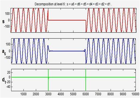
Figure 3. Voltage Interruption and its MRA
Voltage Sag is a reduction of AC voltage at a given frequency for the duration of 0.5 cycles to 1 minute time. The MRA of voltage sag is shown in Figure 4. The coefficient line in detail d1 shows the exact location of the initiation of the disturbance. At the 3000th sample sag is initiated and it is ended after 7000th sample. The voltage sag lasted 10 cycles.
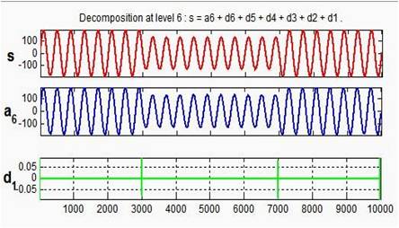
Figure 4. Voltage Sag and its MRA
A swell is the reverse form of sag, having an increase in AC voltage for duration of 0.5 cycles to 1 minute time. The MRA of voltage swell is shown in Figure 5. The coefficient line in detail d1 shows the exact location of the initiation of the disturbance. At the 3000th swell is initiated and it is ended after 7000th sample. The voltage swell lasted 10 cycles.
To differentiate between voltage sag and voltage swell energy of the original signal is compared with approximation a6. If the energy of a6 is larger than original signal, than signal is voltage swell. If the energy of a6 is smaller than original signal, then disturbance is voltage sag.
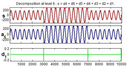
Figure 5.Voltage Swell and its MRA
Impulsive transients are sudden high peak events, that raise the voltage and/or current levels in either a positive or negative direction. The MRA of voltage transient is shown in Figure 6. The coefficient line in detail d shows the exact 1 location of the initiation of the disturbance. At the 4000th transient is detected.
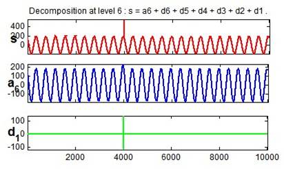
Figure 6. Impulsive Transient and its MRA
Harmonic distortion is the corruption of the fundamental sine wave at frequencies that are multiples of the fundamental. The MRA of voltage harmonics is shown in Figure 7. The coefficient line in detail d6 and d7 shows the presence of harmonics. The approximation a7 reveals the fundamental component. The energy in that level can be used the calculate the THD of the signal using WT.
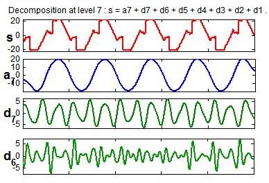
Figure 7.Voltage Harmonics- Real Time Signal and its MRA
Notching is a periodic voltage disturbance caused by electronic devices, such as variable speed drives, light dimmers and arc welders under normal operation. The MRA of voltage notching is shown in Figure 8. The coefficient line in detail d1 shows the exact location of disturbance. In each cycle, there are two peaks indicating the presence of notching. The technique is particularly useful in detection of commutation failure in HVDC.
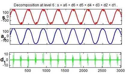
Figure 8. Voltage Notching and its MRA
Noise is an unwanted voltage superimposed on the power system voltage or current waveform. Noise can be generated by power electronic devices, control circuits, arc welding equipment, switching power supplies, etc. The MRA of voltage noise is shown in Figure 9.The coefficient line in detail d1 shows the presence of noise. The approximation a6 reveals the fundamental component.
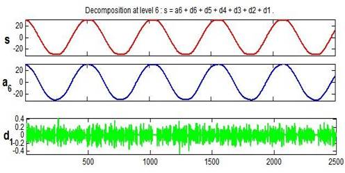
Figure 9. Voltage Noise – Real Time Signal and its MRA
In this paper, the wavelet transform as a new concept to eliminate harmonics for improving "Power Quality" is proposed. These techniques are based on wavelet theory and multi-resolution analysis. The localization property of the wavelet transform is used to detect and classify different disturbances. Any distorted event can be decomposed into different resolution levels. The energy of each resolution level can generate a translation invariant feature vector with small dimensionality, that can be used to classify different disturbances. As for the choice of mother wavelet, which is called the basis wavelet, 6th order Symlet which is familiar to the fundamental waveform is chosen. Symlets also have good functions in detecting transient state. By the use of the acquired a component 7 through this process, harmonic components were eliminated from the original input waveform. The results shows the superiority of Symlet mother wavelet over other wavelet families in detection of power quality disturbances. Symlet mother wavelet was able to distinguish between voltage noise and voltage harmonics signals. Both simulated signals and real time signals are considered and the disturbance are detected and classified correctly.