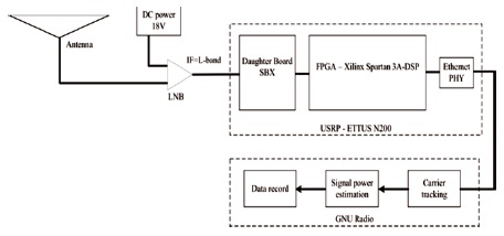
Figure 1. Block Diagram of Proposed System
The Software Defined Radio (SDR) is an advance type of radio communication system. This paper proposes development of a beacon receiver using software defined radio for processing Ka band satellite signals. GNU radio, a free software tool kit, will be used to develop the beacon receiver functionality. The beacon receiver would be used to detect and measure the signal strength of a transmitted beacon signal. The beacon signals are well suitable for propagation measurement due to stable transmitted power and frequency, and also measures the weather data and radio meter. The hardware components needed for this research are parabolic antenna, a low noise block converter, an ETTUS Universal Software Radio Peripheral (USRP) and Linux PC. This beacon receiver would have low cost compared to commercially available analog receivers. Low Noise Block Converter (LNB) is used to convert the incoming Ka band radio frequency signal to L band intermediate frequency. Ka band suffers attenuation due to rain. Beacon receiver is a high performance receiver and it is used to track the power density of the satellite beacon in real time applications. The signal processing blocks are written in C++ and Python to realize SDR.
Radio communication is a modern communication system which is widely used in space applications, military, aerospace, and civilian fields. Conventional communication system is based on hardware for particular purpose and it can be replaced by multimode programmable, versatile radio systems like Software Defined Radio (SDR) and Cognitive Radio (CR).This paper proposes SDR to be developed using GNU radio, a free software tool kit for building software radios. SDR directly communicate with General Packet Radio Services (GPRS), 802.11 based Wi-Fi, and 802.16 based WiMAX, Global Positioning System (GPS) and Global Navigation Satellite System (GNSS). Ku band beacon receiver function is used to study the troposphere conditions (rain attenuation) and telemetry tracking purposes. The Ku band frequency is 14-26 Ghz. Beacon signals transmitted by satellites are low power continuous wave signal for finding antenna direction and power control at earth stations. The satellite beacons are above X-band and they are affected by ionosphere; and when the frequency is increased, the beacons are affected by troposphere. Radio is any system that transmits and/or receives Radio Frequency (RF) signals approximately from 3 kHz to 300 GHz wirelessly. Traditional radio devices are specified by their hardware and can only be used in a particular frequency band and for a specific modulation form. On the other hand, SDR uses Digital Signal Processing (DSP) to handle most of the complex signal processing needed by the traditional baseband communications systems. In a frequency band suitable for wireless transmission and reception, analog equipment is used to convert between a (complex-valued) baseband signal and its corresponding (real-valued) band transfer signal. The SDR consists of a receiving part antenna, An analog-to-digital converter and a digital-to-analog converter connected to a power amplifier and a transmitting part antenna. Then all the sorting and signal processing takes place in the digital domain, which can be managed more efficiently in an economical way than is feasible with conventional analog signal processing. In current practice, DSP is used for frequencies ranging a few hundred MHz, and analog hardware is used for frequencies of several hundred MHz and beyond. The device that translates the digital baseband signal to the analog band pass signal is often referred to as SDR, and the digital baseband signal generating device (computer) is referred to as DSP.
Communications systems of the next generation introduce new challenges that require solutions beyond what can be achieved through the optimization of individual devices. It requires a more frequency-flexible and bandwidth-flexible RF design to integrate more software control and cognitive abilities into the radio. To achieve this goal, it is necessary to remove static filters and replace them with tunable filters. Likewise, a shared interface model would allow shorter design cycles, lower production costs, and greater interoperability between systems.
The standard model allows the RF framework to deliver full performance to systems that have very different architectures historically. Eventually, upcoming networks are moving to a new extreme scale and energy demands. The main advantage of a SDR over a traditional radio is that (most) the operating functions of the radio (often called physical layer processing) are implemented on programmable devices such as Field Programmable Gate Arrays (FPGA), DSPs, General Purpose Computers (GPP), programmable System on Chip (SoC) by means of modifiable and upgradable software and firmware, etc. Using these technologies enables the addition of new wireless features and capabilities to an existing radio system without replacement or modification of its hardware.
To measure troposphere, scintillation a prediction method is presented (Hussein, 2009). From the present method it is concluded that the elevation angle has greater impact on the magnitude of scintillation, followed by the frequency and the diameter of the antenna. Implementation of a Ka -band satellite channel simulator is with an emphasis on scintillation process synthesis. A numerical procedure is devised to calculate the filter and non-linearity coefficients of the Wiener model (Sala et al., 2008). To investigate the atmospheric impairments at Ka band, a beacon receiver based on SDR is designed. To analyze the second order statistics, fade duration and fade slope distribution for scintillation and attenuation is presented. (Hrovat et al., 2016). Low earth orbit (LEO) satellite passing through turbulent media are presented using a geometric model of propagation. The height of the turbulence layer increases and the orbital altitude decreases as the corner frequency of the scintillation process increases (Liu & Michelson, 2010). GNU Radio Beacon Receiver (GRBR) was developed to measure the ionosphere’s Total Electron Content (TEC). For signal processing application, SDR is utilized to realize the basic function of the receiver (Yamamoto, 2008). Frequency Modulation (FM) transmitter and receiver are implemented using the Universal Software Radio Peripheral (USRP) B200 board. The FM receiver of mobile phone and the USRP B200 board receiver received the transmitted audio file (Kushnure et al., 2017). For ionospheric study, the GNU radio beacon receiver has been developed to receive beacon signals from LEO satellites. Satellite tracking program was developed by writing a Python script (Yamamoto, 2008). Using GNU WaveGuru and GNU octave tool, real-time data transmission and reception using various digital modulation techniques such as Gaussian Minimum Shift Keying (GMSK), Gaussian frequency shift keying (GFSK) and Differential phase shift keying (DPSK) are introduced (Anusha et al., 2017). In order to contain lower frequencies, higher frequency bands such as 18–21 GHz, K band must be used for supplementary services (Kikkert a et al., 1999). The rain attenuation decreases as the rate of propagation increases (Machado et al., 2008). At a 150 mm/h rain rate, which is common in the tropics for short durations, an attenuation of 20 dB per Km is observed at 21 GHz, while the same rain only causes a 5 dB per Km attenuation in the 11 – 13 GHz, Ku band", (Kikkert & Kenny, 2008). There is a minimum absorption of water at 22.2 GHz, which means that the signal transmitted is further attenuated by high moisture level. The attenuation due to the water vapor is negligible at C-band and K band (Yamamoto, 2008). Further computational achievements are possible by improving the DSP processor capabilities leading to bigger Fast Fourier Transform (FFT) sizes. A FFT of 4 k compared to the precading 1 k FFT used in previous STRAP systems has been implemented in this case. This results in an increase of 18 dB in device noise efficiency with the use of 12 bits rather than 10 bits Analog to Digital Converters (ADC). Past rain fades in excess of 35 dB showed K band metrics (Tervonen et al., 1998). Such u deep fades are often observed in K band frequencies, a especially in tropical areas. Therefore, a satellite light receiver needs to achieve the widest possible dynamic range.
Ka band research studies have been conducted in various countries, which are related to the frequency of their use and mode of operation (Rai & Nigam, 2012). Commercially accessible from shelve receivers do not meet the needs of the Indian study. Using the conventional super hetrodyne radio design until now, the receivers have been developed and have complex measurement accuracy limitations. The digital receivers system provides greater sensitivity and a broad range of dynamics.
In this paper, a low cost digital beacon receiver based on the SDR is implemented for processing Ka band satellite signals.
Figure 1 displays the block diagram of the proposed system. The transmitter receiver is used to identify and measure the signal strength of the beacon signal transmitted. The parabolic antenna used is with the diameter of 1.2 m. The USRP is a high speed board with USB connection consisting of a motherboard, A-D, D-A converters, and FPGA connected to an IF card slot. The IF card slot contains an analog front end in the range of 800 MHz to 2.4 GHz. Digital down conversion, decimation, filtering, and high speed signal processing tasks are performed by FPGA. Sine and cosine signals are generated using Numerically Controlled Oscillator (NCO). They are multiplied with digitalized samples and converted into complex signals. A Low Pass Filter (LPF) is used to perform filtering and decimation with a factor of 6. LPF can be performed completely at baseband; switches are used to connect the analog baseband circuitry in-between the transceivers baseband input and output. The beacon receiver requirements are defined as signal tracking capability during frequency drift and signal re-acquisition after the temporal loss of signal, normal scintillation tracking for high sampling rate, high reliability, long term operation, and robustness with less interruption.
Figure 1. Block Diagram of Proposed System
GNU Radio is an open source frame network for creation of software and GNU Radio provides signal processing framework to implement radio technology. The essence of the GNU Radio is written in C / C++ and Python. Graphical User Interface (GUI), known as GNU Radio Supporter, can easily generate computer radio programs.
The block diagram of SDR is shown in Figure 2. Software Defined Radio is a radio system, which performs the required signal processing using software instead of dedicated integrated circuits in the hardware. By digitizing radio signals, operations traditionally performed in hardware can be performed in software. Analog components such as filters, mixers and phase locked loops are implemented using digital signal processing techniques. The software radio consists of Low Noise Amplifier (LNA) and Analog to Digital Converter (ADC) and LNA is directly connected to an ADC which is used for both path of reception and transmission, and power amplifier and Digital to Analog Converter (DAC). In the SDR, software standards are implemented in software along with SDR. They are loaded and executed in common hardware platform, which also consists of FPGA and DSP chips. The Modern ADC's can digitize wide bandwidth signals at carrier frequencies upto several hundred MHz.
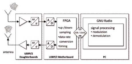
Figure 2. Block Diagram of SDR
The USRP shown in Figure 3 is designed by Ettus Research and it is a range of software defined radio. In this paper, the daughter board is used in USRP N210 network series. The USRP hardware is used to transmit and receive the data, which act as a transceiver. The device contains USRP N210 motherboard to measure the frequency stability and phase difference between WBX daughter board and is used to measure the performance of communication delay, jitter and throughput A/D and D/A converters and these are connected to a Field Programmable Gateway Array (FPGA). The daughter board act as analog front-end and are based on the different range of frequencies from zero to 6.4 GHz.
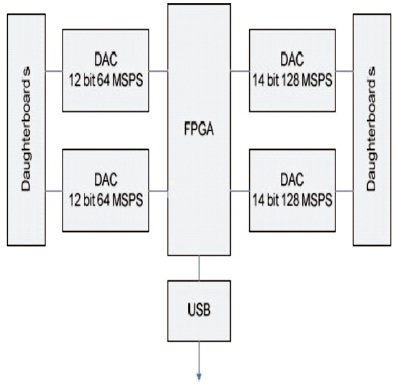
Figure 3. Universal Software Radio Peripheral (USRP)
The block diagram of LNB as shown in Low Noise Block converter is used as receiving device and it collects the radio waves from the dish, convert them to signal. It is a combination of low noise amplifier and mixer, local oscillator and it amplifies the low noise quality of an LNB expressed as noise figure (noise Temperature). The received signal is extremely weak and it has to be amplified before down conversion. LNB is used for two major functions, amplification and frequency conversion.
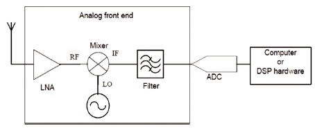
Figure 4. Low Noise Block converter
The daughter board used for this research is WBX 40 (Wide band receiver). The USRP mother board contains two RX and two TX daughter boards. The daughter boards act as an analog front-end and it is possible to use the USRP at different frequencies beyond the frequency limit. The daughter board frequency range covers from 50 MHz to 6.2 GHz. The board contains internal Global Positioning System (GPS) and Gigabit Ethernet capability.
This board can operate the frequency range from 800 MHz to 2.3 GHz and this board is Multiple-Input Multiple- Output (MIMO) capable and is operated in two bands at 900 or 1800 MHz and also has a Low Noise Bock converters (LNB). External front end used for up conversion and down conversion is based on the Maxim MAX2118 direct conversion IC. It has a noise figure of 3-5 dB and a software controlled channel filter. The filter bandwidth can be set to a minimum of 1 MHz or as wide as 60 MHz. The DBSRX is provided DC power through the center lead of a coaxial cable. Originally 6V can be provided by installing a jumper. Connections are provided if other voltages are required. This will however necessitate an external power supply. The local oscillator (LO) used in the mixer is derived from the 64 MHZ crystal oscillator (XO) on the motherboard. So, a tolerance of 5 kHz should be expected at room temperature (Mikkelsen, 2009).
The Universal Software Radio Peripheral (USRP) is a highspeed board with a USB connection that can be used for realizing software radios. The device is made up of motherboard containing four Analog-to-Digital (A/D) and Digital-to- Analog (D/A) converters, each with 12 bits per sample (64 mega-samples/s), connected to a Field- Programmable Gateway Array (FPG A) (Liu & Michelson, 2010). Each of the converters is also connected to an intermediate-frequency (IF) card slot. The IF card contains an analog front end, and covers frequency range from 800 MHz to 2. 4 GHz.
The FPGA is used to perform high-speed signal-processing tasks, such as digital down-conversion, decimation, and filtering. The IF card can be controlled via the motherboard to adjust the mixer frequency and channel filter. A USB 2.0 connection is used to connect the Universal Software Radio Peripheral to the PC. A free software toolkit, GNU Radio was used to develop the basic functionality of the receiver. The signal-processing blocks were written in C++, and Python was used to tie them together. The lower noise block converter first converts the incoming Radio Frequency (RF) signal of the K band into the L-band a IF. The frequency of the DBSRX IF card is set to the intermedia L-band. The signal is then achieved by a PGA and sampled by an A/D converter with a sample rate of 64 MHz. The signal is sampled by the sampled A/D converter.
The samples are multiplied and converted into baseband complex signals by sine and cosine signals, which are produced by the Numerically Controlled Oscillator (NCO). A Cascaded Integrator-Comb (CIC) filter is used to monitor and decimate the signal, minimizing the sampling frequency to 250 kHz (equivalent to a decimating factor of 256). The data will then be sent via USB to the PC.
The frequency of this filter is 20 kHz, with 60 dB attenuating at 22 kHz on the stopband. The ripple of the pass band is 0.01 dB. The signal sampling frequency is reduced to 41.7 kHz at this stage. The measured signal strength, noise intensity, the magnitude of every FFT bin for the signal energy estimation and the local time were reported in a 20 Hz sampling file. The GPS is used to synchronize the PC's clock to prevent clock drift in order to obtain position and direction data. The flowchart of beacon receiver is shown in Figure 5.
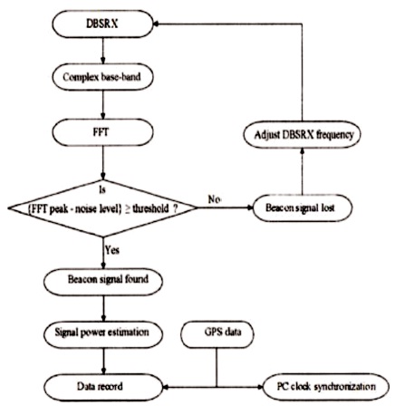
Figure 5. Flowchart of Beacon Receiver.
The difference between the FFT peak and the noise level is less than the threshold.
Extract the GPS data.
Link Budget Calculations
Link budget calculations are of two types of the power calculations.
C/N ratio calculations are simplified by the using of link budget. The design and implementation of beacon receiver link budget is needed. The calculations give the design and requirements of beacon receiver and estimate the performance of communication system of losses and gains in between the transmitter and receiver.
Beacon receiver is a versatile receiver and is designed to lock onto a continuous waveform (CW) or modulated carrier. Based on the link budget calculations, there are two types of beacon receiver designs proposed. One is based on super heterodyne receiver and another one is based on USRP. In this paper, the USRP act as radio trans receiver. It can provide the accurate and reliable power measurement indicators for antenna positioning or uplink power control. The beacon receiver operates in L-band and it accepts the frequency range between 940-2150 MHz and the dynamic range is -100 to -300 dB. The signal generator is used to measure the linearity, dynamic range, sampling rate and other characteristics of the parabolic antenna is used to receiving the signal in Ku band. The results are evaluated in Fast Fourier Transform (FFT).
Displaying an FFT of the USRP spectrum was considered as DC offset, whereas in the output spectrum, 2048 point FFT and 40 kHz of the bandwidth will be displayed. This plot is generated without input signal and gain is zero. The noise floor is above 20 dB and shown in Figure 6.
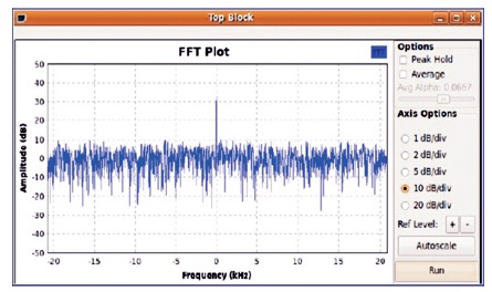
Figure 6. DC Offset with No Input Signal
The signal generator is used to measure the linearity and dynamic range of the USRP. This can be achieved through the range 1.154 GHz sinusoidal wave to the DBSRX daughter board. The generated power signal is set below the noise and increment of 2 dBm until the LNA of the DBSRX reaches to saturation mode as shown in Figure 7. The graph can be plotted relative to the normalized input power. The dynamic range is about 70 dBm and the linear dynamic range is about 60 dB. The linearity measurement is also related to the amount of the distortion (Figure 8) that can be achieved at the high gain settings. Output can be generated and plotted by applying 70 dB sinusoidal wave with gain USRP set to 52 dB. For single plot region, FIR filters are used with the average PSD value to make smooth plots. Then the output spectrum is displayed in signal generator as shown in Figure 9.
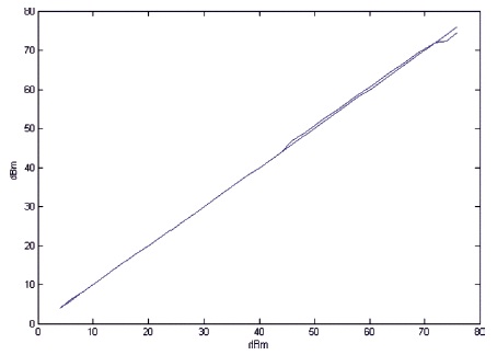
Figure 7. Linearity Measurements of the Beacon Receiver.
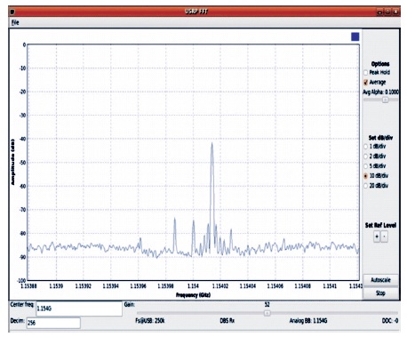
Figure 8. LNA Distortion
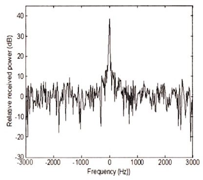
Figure 9. Spectrum of the Eutesat W3A Satellite Beacon.
The radio waves propagating from satellite links are affected by environmental turbulence along the propagation path. Scintillation is the rapid variation of the amplitude and phase of the received signal. In this paper, the study observes the amplitude scintillation (Figure 10) based on ITU-R model.
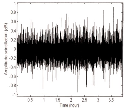
Figure 10. Clear –Sky Amplitude Scintillation.
This model suggests the prediction method for the estimation of the Cumulative Distribution Function (CDF) amplitude scintillation of fade path as shown in Figure 11.
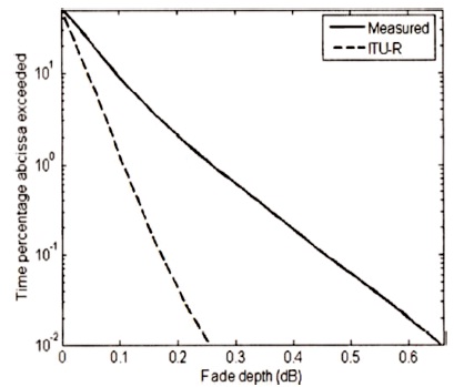
Figure 11. A Comparison of the Measured and Predicted Cumulative Distribution Function of Amplitude Scintillation Fade Depth.
It is based on average data of the temperature, humidity. T(c) and T(H) are used to calculate the wet component of refractivity. Based on ITU-R model, we observed or underestimated the statistical estimate of attenuation. This is might be due to seasonal variations. The probability density of amplitude scintillation is given by,
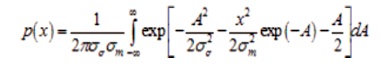
In this model the probability density function is well, but overestimated the statistics for larger log –amplitude values.
Figure 12 shows good agreement between measured (solid line) and theoretical (dash line) amplitude- CDF scintillation spectrum. Additionally, diurnal variations of scintillation intensity were calculated by taking average measured one-hour standard deviation. From Figure 13, we could observe that the scintillation intensity was maximum at noon.
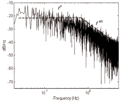
Figure 12. The Measured (Solid Line) and Theoretical (Dash Line) Scintillation Spectra
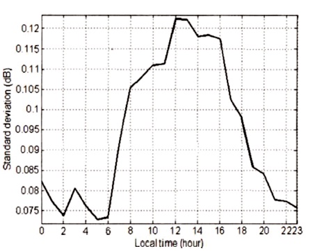
Figure 13. The Average Measured Daily Variations of Standard Deviation of Hourly Amplitude Scintillation.
The SDR has various applications in the research of atmosphere and meteorology. SDR proposed in this paper removes so many bulky devices and equipment used to study low orbit satellites and precipitation in the troposphere. The cost involvement is very less as the development would use GNU Radio, a freely available development tool available under Open Source agreement. We also have reviewed many literature to work on various shortcomings in existing software radios. In our process of developing the software beacon development, many upgrades are being planned based on our ongoing research. The final product will be having high performance used in the real application of tracking low power density satellite beacon.