(1)
In this paper microstrip patch antenna using two rectangular slots with defected ground structure is designed for X–band application. The bandwidth of proposed antenna is increased by using the defected ground structure and slot at solution frequency of 9.3 GHz with microstrip line feeding technique. The radiated rectangular patch is mounted on RT/duroid 5880 dielectric substrate having thickness of 0.508 mm and dielectric loss of 2.2. The return loss of -35.21 dB is obtained and a bandwidth of 910 MHz at a solution frequency of 9.3 GHz in the X-band range is also observed.
Mi crostrip patch antenna is generally used in wireless communication system. The traditional structure of a microstrip patch antenna consists of metallic patch with a grounded substrate. The metallic patch can be used in different configurations like the circular and rectangular patches. The substrate material which has the dielectric constant range between 2.2 ≤ e ≤ 12 can be used as r substrate (Constantine, 2005). The radiated patch can be of any geometrical shape, among which circular and rectangular shape geometry are the most commonly used (Constantine, 2005). The circular and rectangular microstrip patch antennas are generally used because they are simple. These antennas provide the flexibility to microstrip line feeding, multiple frequency application, circular and linear polarizations, frequency agility and wide bandwidth (Julio et al. 1991). These antennas are used in various satellite communications like spacecraft, aircraft, and missile applications. The wide applications of these antennas are due to their properties, such as having low profile, lightweight, compact dimensions, and easy fabrication method (James and Hall, 1989). In the microstrip antenna, use of dielectric substrate is carefully done because different types of substrate characteristics gives different results. The main disadvantage of microstrip antenna is its lesser bandwidth than other antennas.
In the Defected Ground Structure (DGS) technique scaling down the size of microstrip antennas is done. This technique consists of etching a simple shape in the ground plane, or sometimes by a complicated shape for the better performance. The DGS can be formed by an equivalent LC resonator circuit. The total value of capacitance and inductance depends on size and area of the shape. By altering the different dimensions of the etched shape, the desired frequency band can be achieved (Aris et al. 2015). X-band frequency range technology has been mostly used in various applications because of its higher data transfer rate (Jing et al., 2010). It has wide bandwidth and short-range factor (Mohammed et al. 2013a). Designing of microstrip antenna for X- band application has tempted the interest of many researchers (Mohammed et al., 2013b). The most commonly used dielectric substrate in antenna designing is Flame Retardant 4 (Divesh et al., 2016). The selection of substrate is the most significant factor in designing of an antenna.
The proposed antenna can be used in radar application, satellite communication, maritime ship traffic management, medical application, and air traffic control. This antenna can provide information about weather changes also.
The design of the proposed microstrip antenna is done by choosing a rectangular shape radiating element, fed by using microstrip line feeding and printed on RT/duroid 5880 dielectric substrate with the relative permittivity of 2.2 and dielectric loss tangent of 0.0009. The design of antenna consists of a rectangular patch with two rectangular slots, both are of same dimensions (length L = 0.65 mm and 2 width W = 5.51 mm) are removed from the patch in the 3 opposite direction. The first slot is positioned at left side and is 0.77 mm from top edge of the patch. The second slot is positioned at right side and is 2.485 mm from bottom edge of the patch. Microstrip line feeding has been used for feeding. The required dimensions of microstrip line feed are length L =5.57 mm and width W =1.54 mm. The feed line 1 1 is positioned at W =2.93 mm from right edge of the patch. 2 The resonant frequency of a microstrip antenna can be designed on the basis of length and width of the patch. The total impedance of the transmission line is 50 Ω. The defected ground structure is located on the metallic ground plane. In the ground structure, a rectangular shape slot is removed from the ground. The slot position from the right edge of ground plane is 3 mm. This defected ground structure provides altering in the current dissemination of the patch antenna and it also provides change in effective inductance and capacitance of the microstrip patch antenna.
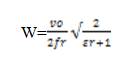
The lengths and width of desired patch can be determined theoretically by mathematical equation using from the required operating frequency (f ) and the relative r permittivity for dielectric substrate (Î). Figure 1 shows r rectangular shape microstrip antenna by using two slot insertion geometry. Figure 2 shows the defected ground structure geometry. Table 1 shows the list of various design parameters of the proposed antenna.
where, u = velocity of light,
e= dielectric constant value of the require substrate.
The effective dielectric constant can be found by,
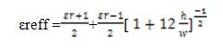
where, h =substrate thickness.
The actual length L, in meters it can be determined by using,
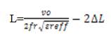
and the insert feed
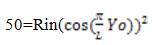
where, R is the input impendence of radiating edge of the in patch while 50 (Ω) is the desired impendence.
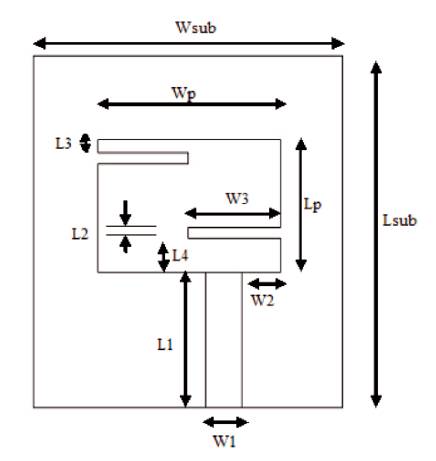
Figure 1. Rectangular Shape Microstrip Antenna using Two Slot Insertion Geometry
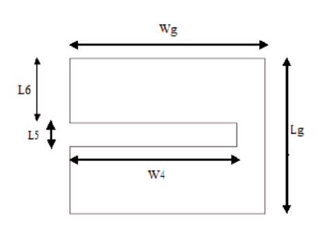
Figure 2. Defected Ground Structure Geometry
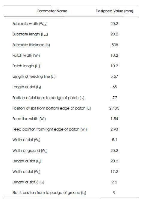
Table 1. List of Various Design Parameters
The simulated result of the proposed microstrip antenna has a minimum return loss of -35.21 dB at 9.6 GHz. The proposed antenna is simulated using Ansoft HFSS v.16 software. The return loss is below than -10 dB between frequency range of 9.16 GHz and 10.07 GHz. The total bandwidth is equal to 910 MHz in the X-band frequency range. The total bandwidth of conventional microstrip antenna is 220 MHz. The defected ground structure increases the bandwidth of microstrip patch antenna from 220 MHz to 910 MHz. The resonant frequency of antenna changes by insertion of slot and defected ground structure. The VSWR value of the proposed antenna is less than 2 in the operating frequency range of 9.16 GHz to 10.07 GHz. The inserted two rectangular slots in the patch change the direction of electric field and gives polarization in desired direction. Figure 3 shows the return loss of the proposed antenna. Figure 4 shows VSWR plot of the proposed antenna. Table 2 shows comparison of bandwidth of the proposed antenna with other antennas.
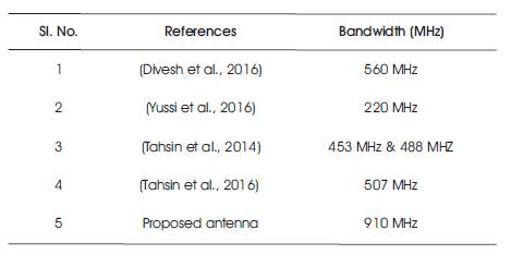
Table 2. Comparison of Bandwidth of the Proposed Antenna
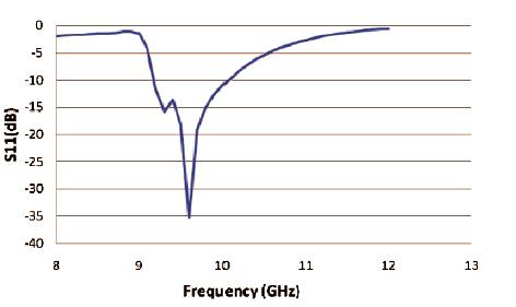
Figure 3. Return Loss of Proposed Antenna (in dB)
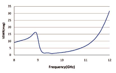
Figure 4. VSWR Plot of Proposed Antenna
In this paper, a rectangular shape microstrip patch antenna with slot utilization and defected ground structure is designed for X-band application. Defected ground structure increases the bandwidth of the proposed antenna. This antenna provides the wide bandwidth in Xband range with use of simple microstrip line feeding technique. The return loss of -35.21 dB is obtained and bandwidth of 910 MHz ranges from 9.16 GHz to 10.07 GHz at a solution frequency of 9.3 GHz in the X-band range is also obtained. The VSWR of proposed antenna is less than 2 from the frequency range between 9.16 GHz to 10.07 GHz in X-band range. The proposed antenna can be used in various applications, such as satellite communications, radar application and air traffic control, etc.