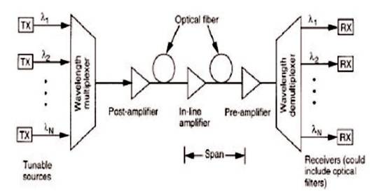
Figure 1. Wavelength Division Multiplexing
This paper investigates the best modulation format among Non Return-to Zero (NRZ), Carrier-Suppressed Return-to-Zero (CSRZ) and Duo Binary (DB) modulation format for long haul transmission system and to find out the best dispersion compensation technique among the pre compensation, post compensation and symmetrical compensation scheme for the 16 channel DWDM (Dense Wavelength Division Multiplexing) system. The channel spacing between the channel is 200 Ghz and all the channel operates at 40 Gbps data rate. The best transmission modulation format is found by varying the signal input power and analyzing the eye diagram from the BER analyzer of the optiSystem software. It is found that DB modulation format with symmetrical compensation technique is the best method for the long haul data transmission. Analysis is done using Optiwave OptiSystem software. The objective of this paper is to compare three different modulation techniques for different modulation formats for long distance communication.
With the increase in demand of high channel capacity and bit rate from the telecommunication industry, optical fiber technology is gaining its popularity[1-3]. It offers some unbeatable advantage over the copper lining such as large bandwidth, low attenuation, low power requirement and resistant to electromagnetic interference. One of the powerful aspects of optical communication link is many different wavelengths carrying independent signal can be send along a single fiber simultaneously. This technology of combining a number of wavelength onto the same fiber is called Wavelength Division Multiplexing technology[4] as shown in Figure 1.
Figure 1. Wavelength Division Multiplexing
WDM technology seems to be the best method to upgrade the link capacity. However, at the multiplexing level of 10 Gbps or more, one starts to encounter such effects that can seriously degrade network performance. Such effects are dispersion and non-linear effect. The interaction of dispersion and non-linearity leads to many degrading effects such as Inter Symbol Interference (ISI), distortion and attenuation of signal in fiber. These signal degrading effects must be managed in order to retain the signal quality. This can be done with the use of dispersion compensated fiber and advanced modulation technique [5-6]. In this paper, the authors investigate the best modulation format among Non Return-to Zero (NRZ), Carrier-Suppressed Return-to-Zero (CSRZ) and Duo Binary (DB) modulation using pre, post and symmetrical format for long haul transmission system on the basis of eye opening penalty for the different input signal power varying from -15 to 10 dBm.
Dispersion is a pulse broadening phenomenon. It is theeffect in which different modes travel with different group velocity due to material and waveguide property of fiber, so that all the modes reach at different time resulting in pulse broadening. Dispersion affects the bandwidth of the system, hence maintaining low dispersion is of equal importance for ensuring increased system information capacity, versatility and cost effectiveness. For the compensation of dispersion, techniques like Dispersion Compensation Fiber (DCF), fiber Bragg grating, optical phase conjugation and electrical compensation methods are adapted. Among this, usage of DCF seems to be the efficient way of compensating the dispersion. DCF offers large negative dispersion which is used to minimize the positive dispersion offered by the Single Mode Fiber (SMF), so that the first order dispersion is zero. The cancellation of dispersion in the fiber link is done by pre, post and symmetrical dispersion compensated technique. In pre compensation technique, DCF fiber is placed before the SMF, in post compensation, DCF fiber is placed after SMF and in symmetrical compensation, DCF fiber is placed in between the SMF[7-9].
When two or more optical fields having different wavelength propagates inside the optical fiber at a high data rate, they interact with each other and give rise to phenomenon called non-linearity. Non-linear effect severely degrades the performance of WDM system[10- 13]. There are several nonlinear effects in the optical link such as Self Phase Modulation (SPM), Cross Phase Modulation (CPM), Four Wave Mixing (FWM), Simulated Raman Scattering (SRS), and Simulated Brillouin Scattering (SBS). The phenomenon of cross phase modulation is described below.
The most dominating phenomenon in WDM system is Cross Phase Modulation (CPM/XPM). Cross Phase Modulation (XPM) is known as the phenomenon that the variations of intensity of one optical signal can change the refractive index of the fiber (Kerr effects), and modulate the phase of other optical signals co-propagating in the same fiber. The change in phase due to variation in power of adjacent channels strongly affect the system performance [14- 15]. XPM leads to inter channel crosstalk in WDM systems and can produce amplitude and timing jitter. Effect of XPM in DWDM system can be analyzed through eye opening. More is the jitter in the eye diagram, also the presence of XPM non-linear effect in the optical link.
Simulation work is carried out in the OptiSystem simulation software. Tables 1 and 2 show the simulation and fiber parameters used in the realization of the system respectively.
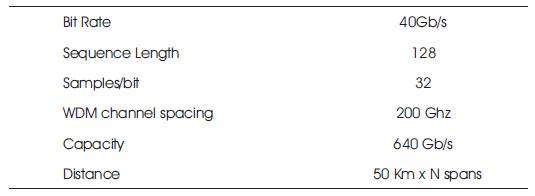
Table 1. Simulation Parameters
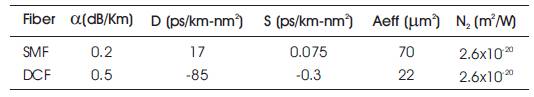
Table 2. Fiber Parameters
Figures 2, 3 and 4 show the block diagram of 16 channel DWDM system for investigating the characteristic performance with pre, post, and symmetrical compensation technique respectively. The entire 16 channel operates at 40 Gbps data rate. The center frequency of first channel is at 191.5 THz and the channel grid maintained between channels is 200 GHz.
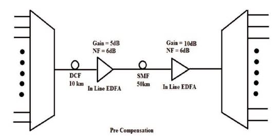
Figure 2. Block Diagram for Pre-Compensation
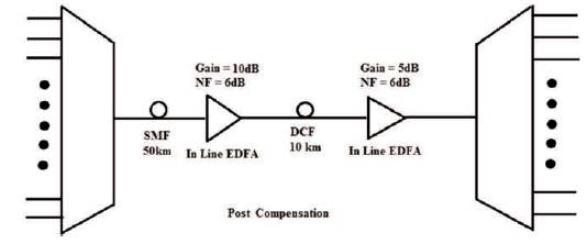
Figure 3. Block Diagram for Post-Compensation
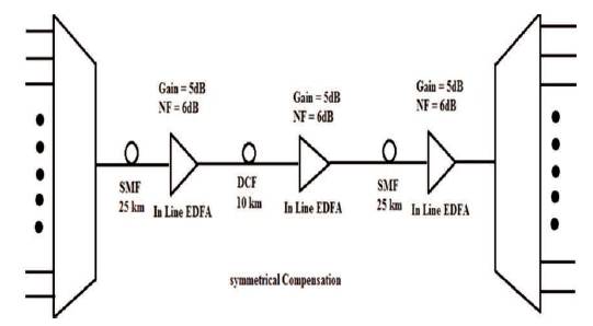
Figure 4. Block Diagram for Symmetrical Compensation
In the simulation setup, the authors have used three different modulation techniques, they are Non Return-to Zero (NRZ), Carrier-Suppressed Return-to-Zero (CSRZ), and Duo Binary (DB) modulation format for all the three dispersion compensated formats. The setup is composed of transmitter, fiber and receiver section. Transmitter section consists of PRBS, CW laser, data modulator and multiplexer, link section consist of arrangements of SMF and DCF to compensate for the dispersion and the receiver comprises of demultiplexer, Photodetector, filter, and BER analyzer. In order to analyze the impact of non-linearities in the DWDM system, the input power is varied from -15 to 10 dBm and the result is analyzed in terms of frequency spectrum and eye diagram.
For analyzing the impact of XPM in the realized system, the input power is varied. Figure 5 shows the eye diagram for NRZ modulation format, Figure 6 shows the eye diagram for CSRZ modulation format, and Figure 7 shows the eye diagram for DB modulation format with pre, post and symmetrical compensation scheme at input power of 0 dBm. It can be seen from the eye diagram that for the modulation technique like NRZ and CSRZ, the effect of XPM is more compared to DB modulation format since there is less jitter in the DB modulated eye diagram. Also the Q value for DB modulation format is more compared to the CSRZ and NRZ modulated system. Thus for the long distance communication, advance modulation formats play a very important role in high speed optical networks[16-21] .
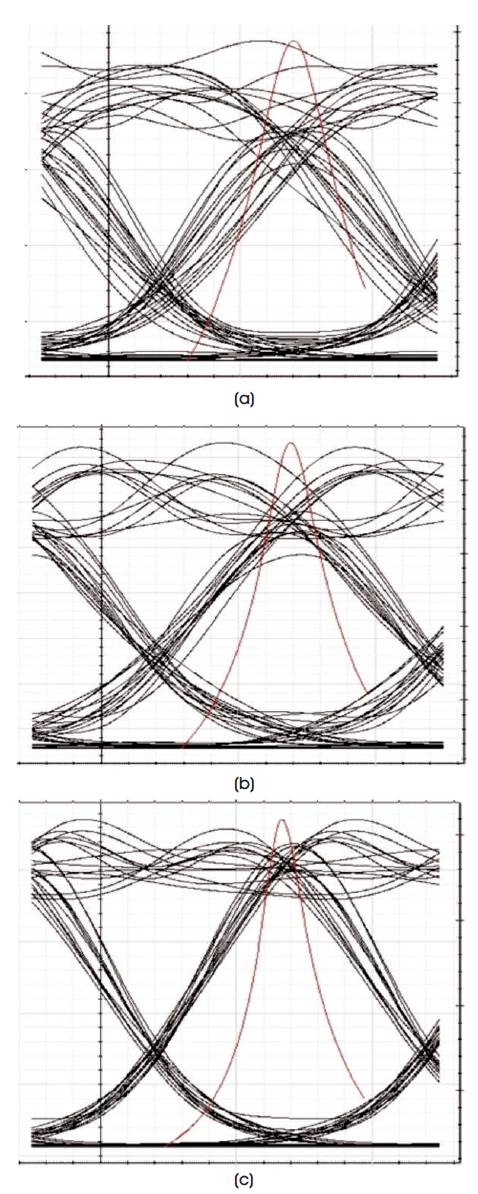
Figure 5. Eye Diagram for NRZ Format with (a) Pre, (b) Post, and (c) Symmetrical Compensation

Figure 6. Eye Diagram for CSRZ Format with (a) Pre, (b) Post, and (c) Symmetrical Compensation
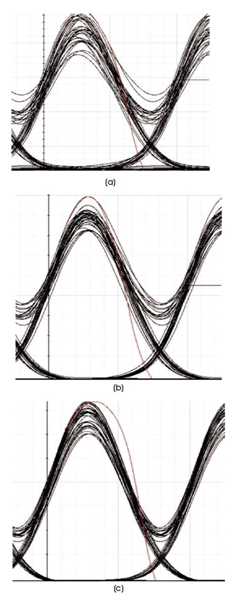
Figure 7. Eye Diagram for DB Format with (a) Pre, (b) Post, and (c) Symmetrical Compensation
In this paper, to minimize the effect of dispersion, dispersion compensation fiber technique is adapted. Dispersion compensating fibers have negative dispersion of -80 to -90 ps/nm.km, which is used to compensate the positive dispersion of Single Mode Fiber (SMF). DCF with negative dispersion is placed before, after or in symmetrical fashion to compensate the dispersion induced by the SMF, so that the first order dispersion is zero.
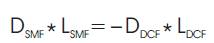
where,
DSMF – Dispersion coefficients of single mode fiber,
DDCF – Dispersion coefficients of dispersion compensated fiber,
LSMF – Length of single mode fiber,
LDCF – Length of dispersion compensated fiber.
Figure 8 shows the graphical representation of Q value as a function of signal input power for pre, post and symmetrical compensation scheme for CSRZ, NRZ and DB modulation format respectively. It can be seen for all the modulation formats that as the signal input power increases, Q value increases up to certain limit (0-5 dBm) after which it starts falling .
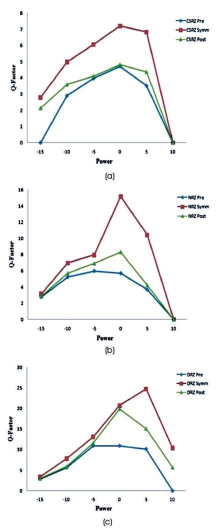
Figure 8. Q value for CSRZ, NRZ, DB for (a) Pre, (b) Post and (c) Symmetrical Compensation Scheme
This can be understood from the fact that for low powers, the performance of DWDM system improves with the increase in input power. However, at higher powers, the wavelengths tend to overlap each other causing more dominance of non-linear effects like XPM and FWM caused by optical Kerr's effect and thus reduces the Q value.
Figure 9 shows the graphical representation of Q value as a function of signal input power for all the modulation formats for pre, post and symmetrical compensation scheme. It can be observed that the worst performance is given by pre-compensation scheme for all the modulation formats and the DB format with symmetrical compensation seems to be most resilient against dispersion and non-linearities[22-26].
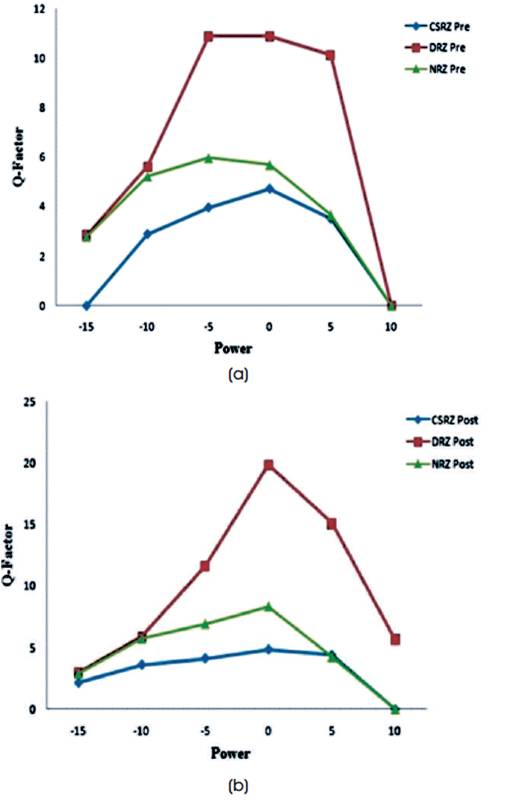
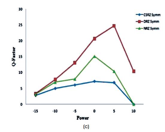
Figure 9. Q Value for the Comparison of Modulation Format for (a) Pre, (b) Post, and (c) Symmetrical Compensation Scheme
In this work, the authors have analyzed 16 channels of a DWDM optical communication system for different dispersion compensation schemes such as pre, post and mix dispersion compensation schemes, using DCF using different modulation system NRZ, CS-RZ, DB at bit rates of 40 Gbps. The outcome of the analysis is that for different power level, each modulation format gives different performance. It is observed that at this high bit rate, DB format gives better performance than others. It is found that mix-dispersion compensation scheme shows better performance as compared to other schemes on the basis of Q factor, Bit Error Rate (BER) and eye opening. Thus it can be said that DB modulation format is faithful for long distance communication using mix dispersion compensation scheme.